Table of Contents
Advertisement
Quick Links
Advertisement
Table of Contents

Related Manuals for Sony XDCA-FS7


Summary of Contents for Sony XDCA-FS7
- Page 1 EXTENSION UNIT XDCA-FS7 SERVICE MANUAL 1st Edition...
- Page 2 Ce manual est destiné uniquement aux personnes compétentes en charge de l’entretien. Afin de réduire les risques de décharge électrique, d’incendie ou de blessure n’effectuer que les réparations indiquées dans le mode d’emploi à moins d’être qualifié pour en effectuer d’autres. Pour toute réparation faire appel à une personne compétente uniquement. XDCA-FS7...
- Page 3 Be sure to keep your PC used for service and checking of this 修理時に使用するパソコンは,ウィルス検出ソフトが常にアッ プデートを行っているパソコンを使用してください。もし,修 unit always updated with the latest version of your anti-virus software. In case a virus affected unit was found during service, 理を行うセット,もしくはパソコンがウィルスに感染している 事が判明した場合は,ソニーグループ内は社内技術相談窓口に, contact your Service Headquarters. 特約店様は特約店様専用電話窓口(修理窓口)にご相談くださ い。 XDCA-FS7...
- Page 4 CRITIQUES POUR LA SÉCURITÉ DE FONCTIONNEMENT. NE COMPONENTS WITH SONY PARTS WHOSE PART NUMBERS REMPLACER CES COMPOSANTS QUE PAR DES PIÈCES SONY APPEAR AS SHOWN IN THIS MANUAL OR IN SUPPLEMENTS DONT LES NUMÉROS SONT DONNÉS DANS CE MANUEL OU PUBLISHED BY SONY.
- Page 5 さい。 また内部配線は引きまわしやクランパによって発熱部品 注意: 半田こてを長く当てすぎると,基板のパターン(銅 や高圧部品に接近しないよう配慮されていますので,こ 箔) がはがれてしまうことがありますので, 注意して れらは必ずもとどおりにして下さい。 ください。 また, 従来の半田よりも粘性が強いため, 4. サービス後は安全点検を IC端子などが半田ブリッジしないように注意してく サービスのために取外したネジ,部品,配線がもとどお ださい。 りになっているか,またサービスした個所の周辺を劣化 ・ 半田こてのこて先は,必ず無鉛半田用と有鉛半田用に分け させてしまったところがないかなどを点検し,安全性が て管理してください。 確保されていることを確認して下さい。 無鉛半田と有鉛半田が混在すると剥離現象が発生してしま 5. チップ部品交換時の注意 います。 ・ 取外した部品は再使用しないで下さい。 ・ タンタルコンデンサのマイナス側は熱に弱いため交 換時は注意して下さい。 6. フレキシブルプリント基板の取扱いについて ・ 半田こてのこて先温度は約350℃に設定してくださ い。 ・ 同一パターンに何度もコテ先を当てないで下さい。 (3回以内) ・ パターンに力が加わらないよう注意して下さい。 XDCA-FS7...
-
Page 7: Table Of Contents
FP-243..........................6-5 XDCA-FS7... - Page 8 HIF-68..........................7-4 Revision History XDCA-FS7...
-
Page 9: Manual Structure
This manual describes the information items that premise the service based on the components parts assuming use of system and service engineers. Related manuals Besides this manual, the following manuals are available. • Operating Instructions (Supplied with this unit) XDCA-FS7... - Page 11 FP-243..........................6-5 XDCA-FS7...
- Page 12 HIF-68..........................7-4 XDCA-FS7...
-
Page 13: 本書の目的
このマニュアルについて 本書の目的 本書は, システムエンジニアやサービスエンジニアの方々にご使用いただくことを想定し, 本機の保守に関 する情報, 部品レベルまでのサービスを前提とした情報を記載しています。 関連マニュアル 本機には,この 「サービスマニュアル」 のほかに, 下記のマニュアルが用意されています。 • 取扱説明書 (本機に付属) XDCA-FS7... -
Page 15: Service Note
• The proper way to disconnect a connector is to grab the connector instead of the wires. If you pull on the wires, they might be broken. • The proper way to connect a connector is to grab the connector instead of the wires. If you push on the wires, they might be broken. XDCA-FS7... -
Page 16: Power Supply During Repairs
1-2. Power Supply during Repairs 1-2-1. AC power adaptor About the power supply during repairs, connect this unit to the PXW-FS7 and be sure to use the AC adaptor (AC-DN10). XDCA-FS7... -
Page 17: サービスノート
コネクター • コネクターの開閉部を開ける際,A 方向に開け過ぎないようにしてください。 開閉部 コネクター フレキシブル基板 • コネクターの開閉部を閉じる際, フレキシブル基板を矢印 B 方向に押しながら, 開閉部を均一に押して ください。 開閉部 コネクター フレキシブル基板 絶縁面 • フラットケーブルおよびフレキシブル基板の端子面に欠け, 折れ等がないことを確認してください。 先端の剥がれたメッキ部はカットして 除去してください。 (メッキ破片がコネクター内に残って いる場合もあるので注意してください) • 金メッキされているフレキシブル基板には,強い負担をかけないでください。 1-1-2. 細線ケーブル • コネクターを取り外す際に,線材部(極細)を持って引っ張ると断線する恐れがありますので,絶対に 線材部 (極細) を持って引っ張らないでください。 • 線材部(極細)を押さえながらコネクターを差し込むと,線材部(極細)が断線する恐れがありますの で, 絶対に線材部 (極細)には負担をかけないでください。 XDCA-FS7... -
Page 18: 修理時の電源供給について
1-2. 修理時の電源供給について 1-2-1. AC アダプタ 修理時の電源供給については本機を PXW-FS7 に接続し, 必ず AC アダプタ (AC-DN10) を使用してください。 XDCA-FS7... -
Page 19: Replacement Of Main Parts
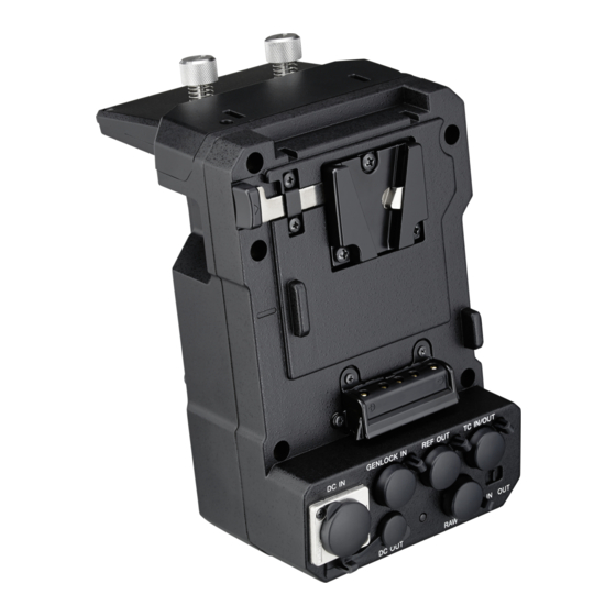
Section 2 Replacement of Main Parts 2-1. Identifying Parts Docking Screw Compression Spring V Mount (B) Assy Top Cover Rear Assy Top Panel CA-89 Board CN-3760 Board CN-3725 Board DC Fan Fan Cover (B) HIF-68 Board Front Chassis Assy XDCA-FS7... - Page 20 View Position Top View Back View Left View Right View Front View Bottom View XDCA-FS7...
-
Page 21: Disassembly
2-2. Disassembly 2-2-1. Front Section • Refer to “Front Section” on exploded view for Ref. No. #326 #326 Front Assy-2 Rear Assy M901 Disassembly Places [3] #326 X 5 Back View #326 #326 XDCA-FS7... - Page 22 Notes on Assembling the Front Section Installing the DC Fan (1) Routing the harness DC Fan Fan Holder (BO) Front view Side view Air Flow Direction of air flow Label (2) Install the Fan Assy Fan Assy Air Flow XDCA-FS7...
- Page 23 Routing the Harness Front Assy Tape (AS (1550)) Tape (AS (1550)) Rear Assy XDCA-FS7...
-
Page 24: Top Section
2-2-2. Top Section • Refer to “Top Section” on exploded view for Ref. No. #105 #105 #105 #105 #105 XDCA-FS7... - Page 25 Disassembly Places [1] #105 X 6 Back View #105 #105 [2] #105 X 4 Back View #105 #105 [3] #49 X 4 Top View [6] #12 X 4 Top View XDCA-FS7...
-
Page 26: Rear Section
2-2-3. Rear Section • Refer to “Rear Section” on exploded view for Ref. No. #325 #325 #282 #135 #135 #135 #282 #282 #282 #324 #105 Supplied #105 with (Note) (Size: 25 x 15 mm) XDCA-FS7... - Page 27 Cut the tape (AS (1550)) to half (25 mm x 15 mm) and tape as shown below. Suppress the tape more than five seconds. CN-3760 Board Tape (AS (1550)) Match the tape to edge of board. CN-3725 Board 1 mm or less XDCA-FS7...
-
Page 29: Repair Parts List
• ここに記載されている部品は, 補修用部品であるため, 回路図 注意 及びセットに付いている部品と異なる場合があります。 電池の交換は、正しく行わないと破裂する恐れがあり • ns: 供給対象外部品。 ます。電池を交換する場合には必ず同じ型名の電池又は • コンデンサの単位でuFはμFを示します。 同等品と交換してください。 • 抵抗の単位Ωは省略してあります。 使用済み電池は、取扱指示に従って処分してください。 金 被:金属被膜抵抗。 サンキン:酸化金属被膜抵抗。 • 外装部品色表示 • インダクタの単位でuHはμHを示します。 例: • 半導体の名称でuA..., uPA..., uPB..., uPC..., uPD...等は (SILVER) :セットの色を表す。 それぞれμA..., μPA..., μPB..., μPC..., μPD...を示します。 (Silver) :部品の色を表す。 XDCA-FS7... -
Page 30: Exploded View
4-559-788-01 COVER (B), FAN 4-563-971-01 FAN CUSHION 4-564-526-01 SPRING, COMPRESSION 4-563-970-01 FAN HOLDER (BO) 4-547-509-01 TAPE, SLIDE 4-547-497-01 SCREW, DOCKING 4-566-895-01 TAPE (AS (1550)) M901 1-855-096-31 DC FAN 2-630-005-31 SCREW (M2), NEW TRUSTER, P2 #326 7-621-773-95 SCREW +B 2.6X6 XDCA-FS7... - Page 31 HARNESS CA-HIF 1-970-516-12 WIRE, CONNECTOR WITH LEAD (GCS) 1-970-518-11 COAXIAL HARNESS CA-HIF 1-970-522-11 SUB HARNESS CA-HIF 4-547-510-01 SHEET, PROTECT 4-565-382-01 SHEET (B1), WP 3-080-204-11 SCREW, TAPPING, P2 2-630-005-31 SCREW (M2), NEW TRUSTER, P2 #105 2-891-494-31 SCREW (M2), NEW TRUSTER, P2 XDCA-FS7...
- Page 32 CAP (DC) #324 3-364-941-01 SCREW (+B) (2.6X5), NYLOK 1-970-521-11 DCIN HARNESS #325 3-742-074-11 SCREW (+B 3X8) 1-970-519-11 DCOUT HARNESS 3-614-294-01 LOCK, SLIDE (B) 3-614-298-01 * KNOB, RELEASE LEVER 3-614-295-03 LEVER, RELEASE (B) 3-614-293-01 * SPPRING, COMPRESSION A-2069-789-A CONNECTOR BLOCK ASSY XDCA-FS7...
- Page 33 Rear Section Note Use this to cut or splice so that it become the designated size. 指定のサイズになるように形状を加工して使用してください。 XDCA-FS7...
-
Page 34: Accessories
3-3. Accessories Except Japanese Model Ref. No. or Q'ty Part No. SP Description 4-566-293-01 * Operating Instructions (ENG- LISH, FRENCH, GERMAN) 4-566-293-11 * Operating Instructions (SPAN- ISH, DUTCH, ITALIAN, PORTUGUESE, SIMPLIFIED CHINESE) XDCA-FS7... - Page 35 Japanese Model Ref. No. or Q'ty Part No. SP Description 4-566-293-01 * 取扱説明書 XDCA-FS7...
-
Page 36: Electrical Parts List
R119 1-218-990-81 SHORT CHIP 0 R120 1-218-990-81 SHORT CHIP 0 C1530 Not supplied CERAMIC CHIP 0.1uF 10% 6.3V C1531 Not supplied CERAMIC CHIP 0.1uF 10% 6.3V R121 1-218-990-81 SHORT CHIP 0 C1533 1-116-720-11 * CERAMIC CHIP 10uF 20% 6.3V XDCA-FS7... - Page 37 CERAMIC CHIP 0.1uF 10% 10V C2367 1-118-041-11 CERAMIC CHIP 4.7uF 10% 10V C2218 Not supplied CERAMIC CHIP 100uF 20% 6.3V C2368 1-118-041-11 CERAMIC CHIP 4.7uF 10% 10V C2219 Not supplied CERAMIC CHIP 0.1uF 10% 10V C2369 Not supplied CERAMIC CHIP 100uF 20% 6.3V XDCA-FS7...
- Page 38 CERAMIC CHIP 1000PF 5% 50V C3020 1-118-386-11 CERAMIC CHIP 0.1uF 10% 16V C2713 1-116-737-11 CERAMIC CHIP 1uF 20% 10V C3021 1-100-756-91 CERAMIC CHIP 0.047uF 10% 50V C2714 1-118-386-11 CERAMIC CHIP 0.1uF 10% 16V C3022 1-118-386-11 CERAMIC CHIP 0.1uF 10% 16V 3-10 XDCA-FS7...
- Page 39 INDUCTOR 1uH FB2903 1-400-580-21 FERRITE, EMI (SMD) L2501 1-481-992-11 INDUCTOR 1uH FB2904 1-400-580-21 FERRITE, EMI (SMD) FB2905 1-400-580-21 FERRITE, EMI (SMD) L2601 1-412-979-21 INDUCTOR 1uH L2602 1-412-987-31 INDUCTOR 4.7uH FB2906 1-416-976-11 FERRITE, EMI (SMD) (3216) L2603 1-469-845-11 INDUCTOR 4.7uH 3-11 XDCA-FS7...
- Page 40 METAL CHIP 33 5% 1/20W R2221 1-218-933-11 METAL CHIP 22 5% 1/16W R1557 1-240-678-91 METAL CHIP 33 5% 1/20W R2222 1-250-507-11 * METAL CHIP 3.3K 1% 1/16W R1558 1-240-678-91 METAL CHIP 33 5% 1/20W R2223 1-250-507-11 * METAL CHIP 3.3K 1% 1/16W 3-12 XDCA-FS7...
- Page 41 METAL CHIP 47K 5% 1/16W R2432 1-694-535-91 SHORT CHIP 0 R2803 1-218-965-11 METAL CHIP 10K 5% 1/16W R2433 1-694-535-91 SHORT CHIP 0 R2804 1-250-471-11 METAL CHIP 100 1% 1/16W R2434 1-694-535-91 SHORT CHIP 0 R2805 1-250-545-11 * METAL CHIP 120K 1% 1/16W 3-13 XDCA-FS7...
- Page 42 RES, NETWORK 22 (1005X4) R3016 1-250-543-11 * METAL CHIP 100K 1% 1/16W RB2201 1-234-938-21 * RES, NETWORK 3.3K (1005X4) R3017 1-250-519-11 METAL CHIP 10K 1% 1/16W RB2301 1-234-377-21 RES, NETWORK 4.7K (1005X4) R3018 1-250-543-11 * METAL CHIP 100K 1% 1/16W 3-14 XDCA-FS7...
- Page 43 TP2004 1-535-877-22 CHIP, CHECKER VDR301 1-803-742-21 VARISTOR, CHIP VDR302 1-803-742-21 VARISTOR, CHIP X2101 1-814-363-11 QUARTZ CRYSTAL UNIT (25MHz) X2102 1-814-185-11 OSCILLATOR, CRYSTAL (148.5MHz) X2201 1-813-493-11 OSCILLATOR, CRYSTAL (33.333MHz) X2500 1-813-824-11 OSCILLATOR, CRYSTAL (100MHz) X3001 1-813-329-11 OSCILLATOR, CRYSTAL (1.8432MHz) 3-15 XDCA-FS7...
-
Page 45: Block Diagrams
(MONI)2_(TC)_TC_OUT S3801 TIMECODE OUTPUT Q2003 (8/11) (MONI)2_(TC)_TC_OUT, D3801 TALLY_LED_VCC IC2703 IC2705 LED DRIVE (TC)2(MONI)_TC_IN (TC)2(MONI)_TC_IN (MONI)2(TC)_TC_OUT, (TC)2(MONI)_TC_IN (ACCESS) 29, 30 29, 30 3, 5 TIMECODE INPUT (8/11) Q3023 CN3003 REC_TALLY (BODY)2_(IC_101)_REC_TALLY (BODY)2_(IC_101)_REC_TALLY (BODY)2(IC_101)_REC_TALLY DC OUT REC_TRIGGER (IC_101)2(BODY)_REC_TRIGGER (IC_101)2(BODY)_REC_TRIGGER (IC_101)2(BODY)_REC_TRIGGER XDCA-FS7... -
Page 46: Power (1/2)
FP-243 FLEXIBLE CN-3760 BOARD CLOCK BUFFER FB2104 CURRENT LIMITER FLASH MEMORY BOARD (2/11) (8/11) (4/11) CN2007 CN3801 +3.3V D3801 IC2702 (RECORDING) VIDEO SYNC (IC_2101)_2(L980)_PWREN IC2503 IC2305 FB2500 SEPARATOR CLOCK DRIVER (8/11) BUFFER (6/11) (4/11) IC2306 (IC_2101)_2(FAN)_PWM BUFFER (FAN)2_(IC_2101)_FG (4/11) XDCA-FS7... -
Page 47: Power (2/2)
+1.0V_AVCC TIMECODE INPUT AVIN FB2301 +2.5V_IC_2101 IC2604 (8/11) PVIN L2901 VIDEO SWITCH (7/11) IC2903 IC2704 -5.0V REG TIMECODE OUTPUT (10/11) (8/11) L2603 FB2901 FB2904, FB2905 IC2605 L2904 IC2601 +2.5V_IC_2101 L2604 VIDEO AMP DIGITAL VIDEO (7/11) SHDN ENCODER (7/11) +2.5V_IC_2101 XDCA-FS7... -
Page 49: Frame Schematic Diagrams
FP-244 FLEXIBLE BOARD (FAN) DC OUT CN3902 Flexible Flat Cable (HIF-CN3782_6PIN) J3701 CN-3760 BOARD (SIDE A) RAW OUT S3801 D3801 IN/OUT (RECORDING) FP-243 FLEXIBLE BOARD J3801 J3803 J3802 TC IN/OUT REF OUT GENLOCK IN CN-3760 BOARD (SIDE B) CN3801 XDCA-FS7... -
Page 51: Schematic Diagrams
のないように注意してください。 • As the imager may be damaged by static electricity from its structure, handle it carefully like for the MOS IC. In addition, ensure that the receiver is not covered with dusts nor exposed to strong light. XDCA-FS7... - Page 52 EXT_DC_IN(+) (BODY)2_(IC_101)_HIF_CLK (11/11) EXT_DC(-) BATT_IN(+) CN3001 BATT_IN(+) Through the SUB HARNESS CA-HIF 41 42 43 44 45 46 CN104 BATT-IN(+) BATT-IN(+) BATTERY_IN BATT-SCL (IC_101)_2(BODY)_BATT_SCL BT901 BATT-SDA (IC_101)_2(BODY)_BATT_SDA BATTERY BATT-ID (IC_101)_2(BODY)_BATT_ID TERMINAL CA-89 BOARD BATT-IN(-) BATT-IN(-) XX MARK: NO MOUNT XDCA-FS7...
- Page 53 R3702 4.7u FLEXIBLE SDI_TXN0 (RMON)2(SDI)_TXP0 2 3 4 5 LND001 SDI_TXP0 R3709 R3710 IC3702 GS2978-CNTE3Z C3705 R3708 SDI TRANSMITTER SD/HD 4.7u (RMON)2(SDI)_EN0 SDI_EN0 RSET VDR374 CL3701 C3703 DCOUT_OVC_1 0.1u ET3701 ET3702 C3704 R3705 CN-3725 BOARD XX MARK: NO MOUNT XDCA-FS7...
- Page 54 CN-3760 BOARD XX MARK: NO MOUNT CN-3782 R3901 LND391 R3902 LND392 CN3902 CN3901 M901 (FAN) FAN_GND FAN_GND HIF-68 FAN_GND FAN_FG R3903 (9/11) FAN_FG FAN_OUT CN2802 Through the N.C. FAN_OUT C3901 (HIF-CN3782 6PIN) FAN_OUT CN-3782 BOARD XX MARK: NO MOUNT XDCA-FS7...
- Page 55 TC_OUT TC_SEL TC_SEL TALLY_LED_VCC TALLY_LED_VCC TALLY_LED_VCC1 TALLY_LED_VCC1 FP-243 FLEXIBLE BOARD XX MARK: NO MOUNT FP-244 LND001 LND002 +5.0V +5.0V +5.0V +5.0V HIF-68 CN-3725 (1/11) SDI_TXN0 SDI_TXN0 CN3701 CN2003 SDI_TXP0 SDI_TXP0 SDI_EN0 SDI_EN0 FP-244 FLEXIBLE BOARD XX MARK: NO MOUNT XDCA-FS7...
- Page 56 C2003 INVERTER 0.1u D2001 D2003 (CN)2_(IC_2101)_REFDET_X 1SS362-TE85L 1SS362-TE85L D2002 D2004 C2001 R2004 1SS362-TE85L 1SS362-TE85L 100p +3.3V TP2002 TP2004 Q2002 TP2001 TP2003 (BODY)2_(IC_101)_REC_TALLY DTA123JE-TL INVERTER Q2003 DTC144EE-TL HIF-68 BOARD (1/11) (CN)2_(IC_2101)_SYNCDET_X LED DRIVE C2004 100p R2018 XX MARK: NO MOUNT XDCA-FS7...
- Page 57 R2152 C2115 0.1u (CN_100)_2(MONI)_MONI0_TX0_P MGTXRXP3_117 MGTXRXN3_115 0.1u C2114 C2126 0.1u (CN_100)_2(MONI)_MONI0_TX0_N MGTXRXN3_117 IC2101 (4/19) R2135 XC7K325T-L2FBG900E IC2101 (3/19) FPGA (CLK)2_(IC_2101)_148MP OUT+ XC7K325T-L2FBG900E FPGA (CLK)2_(IC_2101)_148MN OUT- X2102 HIF-68 BOARD (2/11) 148.5MHz IC2104 DS90LV011ATMF DIFFERENTIAL LINE RECEIVER XX MARK: NO MOUNT XDCA-FS7...
- Page 58 (NEP)_2_(IC_2101)_OUIRDY3 R2205 HIF-68 BOARD (3/11) R2214 R2215 R2213 R2218 IO_L13N_T2_MRCC_15 IO_L14N_T2_SRCC_17 (IC_2101)_2_(NEP)_IUIRXCLK3 IO_L13N_T2_MRCC_14 (NEP)_2_(IC_2101)_OUITXCLK1 IO_L13P_T2_MRCC_16 IO_L13P_T2_MRCC_17 (NEP)_2_(IC_2101)_OUITXCLK3 IC2101 (7/19) IC2101 (8/19) IO_L13N_T2_MRCC_16 XC7K325T-L2FBG900E XC7K325T-L2FBG900E IO_L13N_T2_MRCC_17 FPGA FPGA IC2101 (9/19) IC2101 (10/19) XC7K325T-L2FBG900E XC7K325T-L2FBG900E XX MARK: NO MOUNT FPGA FPGA XDCA-FS7...
- Page 59 C2323 C2382 XC7K325T-L2FBG900E +5.0V R2330 0.1u FPGA IC2302 100k MP2105DJ-LF-Z 1.5V REG POWER_EN_2ND_GP +1.5V_DDR3_IO L2301 2.2uH R2310 330k C2383 C2309 C2380 C2305 0.1u R2311 0.1u 220k FB2301 +2.5V +2.5V_IC_2101 HIF-68 BOARD (4/11) +3.3V +3.3V_VCC12_14 L2313 XX MARK: NO MOUNT XDCA-FS7...
- Page 60 IO_L16N_T2_18 (IC_2101)_2_(CN_100)_G_N0 IO_L16N_T2_34 R2417 IO_L15P_T2_DQS_18 (IC_2101)_2_(CN_100)_G_P1 IO_L15P_T2_DQS_34 R2418 IO_L15N_T2_DQS_18 (IC_2101)_2_(CN_100)_G_N1 IO_L15N_T2_DQS_34 R2424 IO_L14P_T2_SRCC_18 (IC_2101)_2_(CN_100)_G_P3 IO_L14P_T2_SRCC_34 R2425 IO_L14N_T2_SRCC_18 (IC_2101)_2_(CN_100)_G_N3 IO_L14N_T2_SRCC_34 IO_L13P_T2_MRCC_18 IO_L13P_T2_MRCC_34 IO_L13N_T2_MRCC_18 IO_L13N_T2_MRCC_34 HIF-68 BOARD (5/11) IC2101 (16/19) IC2101 (17/19) XC7K325T-L2FBG900E XC7K325T-L2FBG900E FPGA FPGA XX MARK: NO MOUNT 6-10 XDCA-FS7...
- Page 61 IO_L14N_T2_SRCC_33 IO_L14N_T2_SRCC_32 CL2502 AG10 AD18 (IC_2101)_2(DDR3)_RFCLK_P R2504 (IC_2101)_(DDR3)_DQ17 IO_L13P_T2_MRCC_32 IO_L13P_T2_MRCC_33 OUT+ R2506 (IC_2101)_(DDR3)_DQ20 AH10 AE18 R2500 HIF-68 BOARD (6/11) IO_L13N_T2_MRCC_32 IO_L13N_T2_MRCC_33 R2505 (IC_2101)_2(DDR3)_RFCLK_N IC2101 (18/19) IC2101 (19/19) OUT- X2500 XC7K325T-L2FBG900E XC7K325T-L2FBG900E 100MHz FPGA FPGA XX MARK: NO MOUNT 6-11 XDCA-FS7...
- Page 62 VIDEO SWITCH COMP2 R2603 2.7k +3.3V RSET2 R2608 EXT_LF C2609 RESET 1000p L2601 C2608 R2604 0.0047u R2610 R2611 C2617 3.3k R2601 100k C2622 R2625 CL2604 (IC_2101)_2(SEL)_TEST_CPST (IC_2101)_2(SEL)_TEST_HDY R2616 (IC_2101)_2(CPST_C)_27M R2612 R2613 R2615 HIF-68 BOARD (7/11) XX MARK: NO MOUNT 6-12 XDCA-FS7...
- Page 63 0.1u IC2702 LMH1980MM VIDEO SYNC SEPARATOR L2701 C2705 R2703 R2710 22nH 0.1u MARK (CN)2(L980)_REF_IN (L980)2_(IC_2101)_F REXT OEOUT C2704 BPOUT C2708 180p CSOUT (L980)2_(IC_2101)_V VSOUT C2702 R2702 (L980)2_(IC_2101)_H HSOUT HIF-68 BOARD (8/11) Q2701 DTC114TE-TL INVERTER XX MARK: NO MOUNT 6-13 XDCA-FS7...
- Page 64 COMP R2803 EPAD C2808 R2807 C2806 C2807 R2802 IC2801 C2801 4.7u 0.01u 4.7k TPS61170DRVR 0.22u FAN MOTOR DRIVE IC2802 LM73CIMK-0 TEMPERATURE SENSOR C2809 (IC_2101)_(TEMP)_SDA ADDR SMBDAT 0.1u ALERT HIF-68 BOARD (9/11) +3.3V SMBCLK (IC_2101)_2(TEMP)_SCL XX MARK: NO MOUNT 6-14 XDCA-FS7...
- Page 65 100k C2942 C2908 0.1u R2950 R2951 3.3k L2901 C2912 L2904 10uH 10uH FB2901 IC2903 LT1931ES5#TR FB2904 FB2905 -5.0V REG R2925 C2913 100p SHDN C2906 R2926 C2915 C2919 C2923 0.01u HIF-68 BOARD (10/11) D2901 RSX101VA-30TR XX MARK: NO MOUNT 6-15 XDCA-FS7...
- Page 66 IO/DIFFIO_B1N IO_62 IO/DIFFIO_B1P IO/DIFFIO_T1P IO/DIFFIO_L1P R3052 CN3002 +3.3V_DC RB3002 R3013 C3020 C3022 0.1u 0.1u N.C. CL3001 CL3002 X3001 (FOR CHECK) R3045 D3007 D3008 RB3001 1.8432MHz N.C. C3014 0.1u HIF-68 BOARD (11/11) N.C. R3014 N.C. XX MARK: NO MOUNT 6-16 XDCA-FS7...
- Page 67 • As the imager may be damaged by static electricity from its structure, handle it carefully like for the MOS IC. In addition, ensure that the receiver is not covered with dusts nor exposed to strong light. XDCA-FS7...
- Page 68 CA-89 CA-89 BOARD (SIDE A) CA-89 BOARD (SIDE B) CN100 CL021 IC101 R100 R101 FL101 CL002 F100 CN105 CL023 CL022 CN102 CN101 CN104 CN108 CN103 1-894-283- 11 1-894-283- 11 DC IN XDCA-FS7...
- Page 69 CN-3760 BOARD (SIDE B) D3801 IN/OUT S3801 J3801 J3803 J3802 1-894-285- 11 1-894-285- 11 TC IN/OUT REF OUT GENLOCK IN CN-3782 CN-3782 BOARD (SIDE A) CN-3782 BOARD (SIDE B) CN3901 LND391 LND392 R3902 CN3701 CN3902 1-894-471- 11 1-894-471- 11 XDCA-FS7...
- Page 70 C2807 L2701 R2807 C3035 R2803 VDR302 VDR301 R3083 IC2801 Q2001 C2804 D2004 D2003 Q3022 CL2015 C2001 R3081 R3053 R3058 R2009 C3030 CN2003 CN2007 C2803 CL3020 CL3021 R3059 CN3003 D3004 L2801 C2802 CL3022 TH2801 1-894-282- 11 1-894-282- 11 DC OUT XDCA-FS7...
- Page 71 Revision History Ver. Date History Contents S.M. Rev. issued 2014.11 Official Release ― ― XDCA-FS7...
- Page 74 Printed in Japan Sony Corporation XDCA-FS7 (ALL) 2014. 11 08 9-896-715-11 © 2014...