Fujitsu AIRSTAGE ARXK007GLFH Installation Manual
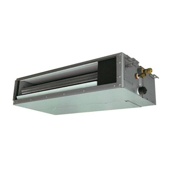
Indoor unit
Hide thumbs
Also See for AIRSTAGE ARXK007GLFH:
- Operating manual (6 pages) ,
- Operating manual (6 pages) ,
- Installation manual (15 pages)
Table of Contents
Advertisement
Quick Links
ARXK007GLFH
ARXK009GLFH
ARXK012GLFH
ARXK014GLFH
ARXK018GLFH
ARXK024GLFH
(Without drain pump)
ARXK004GLGH
ARXK007GLGH
ARXK009GLGH
ARXK012GLGH
ARXK014GLGH
ARXK018GLGH
ARXK024GLGH
(With drain pump)
Refer to the rating label for the serial number,
manufactured year and month.
TM
INSTALLATION MANUAL
INSTALLATIONSANLEITUNG
MANUEL D'INSTALLATION
MANUAL DE INSTALACIÓN
Únicamente para personal de servicio autorizado.
MANUALE DI INSTALLAZIONE
A uso esclusivo del personale tecnico autorizzato.
ΕΓΧΕΙΡΙΔΙΟ ΕΓΚΑΤΑΣΤΑΣΗΣ
ΕΣΩΤΕΡΙΚΗ ΜΟΝΑΔΑ (Τύπος αγωγού)
Μόνο για εξουσιοδοτημένο τεχνικό προσωπικό.
MANUAL DE INSTALAÇÃO
UNIDADE INTERIOR (Tipo de tubagem)
РУКОВОДСТВО ПО УСТАНОВКЕ
Только для авторизованного обслуживающего персонала.
INDOOR UNIT (Duct type)
For authorized service personnel only.
INNENGERÄT (Kanaltyp)
Nur für autorisiertes Fachpersonal.
UNITÉ INTÉRIEURE (type conduit)
Pour le personnel agréé uniquement.
UNIDAD INTERIOR (Tipo conducto)
UNITÀ INTERNA (tipo a condotto)
Apenas para técnicos autorizados.
ВНУТРЕННИЙ МОДУЛЬ (Короб)
MONTAJ KILAVUZU
İÇ ÜNİTE (Kanal tipi)
Yalnızca yetkili servis personeli için.
PART No. 9381858132
MADE IN P.R.C.
[Original instructions]
Advertisement
Table of Contents

Related Manuals for Fujitsu AIRSTAGE ARXK007GLFH


Summary of Contents for Fujitsu AIRSTAGE ARXK007GLFH
- Page 1 INSTALLATION MANUAL INDOOR UNIT (Duct type) For authorized service personnel only. INSTALLATIONSANLEITUNG INNENGERÄT (Kanaltyp) Nur für autorisiertes Fachpersonal. MANUEL D’INSTALLATION ARXK007GLFH ARXK009GLFH UNITÉ INTÉRIEURE (type conduit) ARXK012GLFH Pour le personnel agréé uniquement. ARXK014GLFH MANUAL DE INSTALACIÓN ARXK018GLFH UNIDAD INTERIOR (Tipo conducto) ARXK024GLFH Únicamente para personal de servicio autorizado.
-
Page 2: Table Of Contents
INSTALLATION MANUAL This mark indicates procedures which, if improperly performed, PART No. 9381858132 CAUTION might possibly result in personal harm to the user, or damage to VRF system indoor unit (Duct type) property. Read carefully all security information before use or install the air conditioner. Do not attempt to install the air conditioner or a part of the air conditioner by yourself. -
Page 3: Accessories
2.3. Accessories 2.4. Optional parts WARNING Description Model Application For installation purposes, be sure to use the parts supplied by the manufacturer or other IR receiver unit UTY-TRHX For the wireless remote controller. prescribed parts. Remote sensor UTY-XSZX Room temperature sensor The use of non-prescribed parts can cause serious accidents such as the unit to fall, water leakage, electric shock, or fire. -
Page 4: Installation Dimensions
3.2. Installation dimensions 3.3. Installing the unit Provide a service access for inspection purposes. WARNING Do not place any wiring or illumination in the service space, as they will impede service. Install the air conditioner in a location which can withstand a load of at least 5 times the Installation Dimensions weight of the main unit and which will not amplify sound or vibration. - Page 5 Side inlet - Side outlet 3.3.2. Install the filters • Install the filters to the unit. Insulation material (locally purchased) Aluminum tape Flange (locally purchased) Filter (locally purchased) Duct (locally Intake grille purchased) (locally pur- chased) Side inlet - Side outlet (duct) Flange (locally purchased) Insulation material (locally purchased) Aluminum tape...
-
Page 6: Pipe Installation
3.3.4. Fix the unit 4. PIPE INSTALLATION (1) Hang the unit Hanger CAUTION Hanger bolt Be more careful that foreign matter (oil, water, etc.) does not enter the piping than with refrigerant R410A models. Also, when storing the piping, securely seal the openings by pinching, taping, etc. -
Page 7: Installing Heat Insulation
4.3.1. Flaring 4.4. Installing heat insulation Use special flare tool exclusive for R410A. Install the heat insulation material after performing a refrigerant leak check (refer to the (1) Cut the connection pipe to Check if [L] is installation manual for the outdoor unit for details). the necessary length with a flared uniformly pipe cutter. -
Page 8: Arxk***Glfh Model
5.1.2. When drain pump is not used (Natural drainage) (2) Be sure to connect Applying Drain pipe with adhe- area of Joint pipe (lo- CAUTION sive (polyvinyl chloride) adhesive cally purchased) so that there is no Set “7.5. Switching of drainage func- leakage. -
Page 9: Electrical Wiring
Check for drainage (when drain pump is used) CAUTION Pour about 1 liter of water from the position shown in Earth (Ground) the unit. the diagram or from the airflow outlet to the dew tray. Do not connect the earth (ground) cable to a gas pipe, water pipe, lightning rod, or a Check for any abnormalities such as strange noises telephone earth (ground) cable. -
Page 10: Wiring Method
B. For strand wiring 6.2. Wiring method (1) Use ring terminals with insulating sleeves as shown in the figure below to connect to Example the terminal block. (2) Securely clamp the ring terminals to the cables using an appropriate tool so that the Outdoor unit or RB unit *1 cables do not come loose. -
Page 11: Optional Parts Wiring
(2) Connect the connection cable. 6.5.2. Power indicator lamp status Power indicator lamp (Green) Status contents Lit when the power is turned on. There is a fault with the communication board or the Fast flashing (every 0.1 Y1,Y2: Remote second) main board. -
Page 12: External Input And External Output (Optional Parts)
6.6. External input and external output (optional parts) P.C.B 6.6.1. External input • Indoor unit can be operation/stop, emergency stop or forced stop by using indoor unit CNA02 PCB CNA01 or CNA02. • “Operation/Stop” mode, “Emergency stop” mode or “Forced stop” mode can be selected with function setting of indoor unit. -
Page 13: Remote Sensor (Optional Parts)
6.6.2. External output 7. FIELD SETTING • A twisted pair cable (22AWG) should be used. Maximum length of cable is 25 m. There are 3 methods for address setting by field setting as follows. • Use an external input and output cable with appropriate external dimension, depending Set by either of the methods. -
Page 14: Custom Code Setting
7.2. Custom code setting 7.5. Switching of drainage function Selecting the custom code prevents the indoor unit mix-up. If contained drain pump is not used, set the drainage function to “Invalid” in the drainage (Up to 4 codes can be set.) function switching. -
Page 15: Test Run
Function 10. ERROR CODES Function Setting number Default Details number If you use a wired type remote controller, error codes will appear on the remote controller Forced ther- display. If you use a wireless remote controller, the lamp on the photodetector unit will mostat off output error codes by way of blinking patterns.