Advertisement
Quick Links
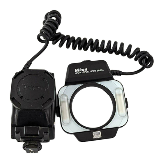
Macro Speedlight
SB-29
Instruction Manual
E
T9L0500202 (S720) 11
Foreword
Thank you for purchasing the Nikon Macro Speedlight SB-29, an easy-to-use
flash unit offering you the most convenient system for close-up flash
photography in combination with Micro-Nikkor lenses. To get the most out of
your new SB-29, read this instruction manual thoroughly before use and keep
it handy, so that you can refer to it whenever necessary.
Tips on using the Speedlight
•Before using this unit, read "Tips on Speedlight care" and "For safe handling of the
Speedlight" on the reverse side of this sheet.
•Take some trial shots.
Before taking important flash photographs, take some test shots to ascertain the
SB-29 is working properly.
•Use only Nikon-approved equipment.
The SB-29 is designed for use with Nikon cameras, lenses and accessories. Using
cameras or accessories other than those specified by Nikon may damage the SB-29.
Nikon cannot be held responsible for malfunctions caused by using the SB-29 in
ways not specified in this manual, or using the SB-29 with a camera made by another
manufacturer.
For details on appropriate Nikon cameras, lenses, and accessories, read each
product's instruction manual.
Nomenclature
1
2
3
5
6
4
Controller
Main unit
7
19
20
8
9
10
15
11
16
12
17
18
13
Controller
21
14
Main unit
22
φ52mm
23
25
φ62mm
24
26
φ72mm
Accessories
ø52mm, ø62mm, ø72mm Adapter Rings
Hard Case SS-29
Aperture/reproduction ratio panel
01 AF assist illuminator lamp button
16 Battery chamber lid
02 Modeling illuminator button
17 Ready-light
03 TTL multiple flash terminal
18 FLASH button
(Remove the terminal cover from the
19 Flash module selector
terminal and turn it counterclockwise by
Firing both flash modules at the same time
90˚ when using the TTL multiple flash
or either independently can be selected.
terminal.)
20 Light reducer setting dial
04 Sync flash terminal
The ratio of the brightness of the right
05 Light reducer
flash module to the left one (or vice versa)
06 Flash modules
can be set to 1:4 using the built-in light
07 AF assist illuminator lamp
reducer.
08 Flash mode indicator LED
21 Adapter ring mounting buttons
09 Flash mode selector
22 Reproduction ratio scale
10 Overexposure warning indicator LED
(1:5 represents 1/5x.)
11 Power switch
23 ISO film speed scale
12 Mounting foot
24 Effective f-number (aperture)
13 Hot shoe contacts
25 Focal length of lens in use
14 Mounting foot lock nut
26 Proper exposure range
15 Alignment indices
No reproduction in any form of this manual, in whole or in part (except for brief quotation in critical articles or
reviews), may be made without written authorization from NIKON CORPORATION.
NIKON CORPORATION
FUJI BLDG., 2-3, MARUNOUCHI 3-CHOME, CHIYODA-KU, TOKYO 100-8331, JAPAN
Printed in Japan
Major features of the SB-29
The SB-29 consists of the main unit and controller. Attach the main unit to the
lens or to the front of the controller to take effective close-up flash
photographs. With the SB-29, you can shoot ultra close-up photographs of
flowers, insects or small objects in the TTL auto flash mode.
The main unit can be attached to the lens
to take close-up flash photographs.
•The main unit can be rotated while pressing the
adapter ring mounting buttons lightly, allowing you to
set the flash modules at any position to match subject
conditions or your creative preferences.
•Close-up flash photography with a lens mounted in the
reverse position is possible. (Optional Adapter Rings
are required.)
The main unit can be attached to the
controller to take close-up flash
photographs.
As shown in the illustration, the main unit can be rotated
up to 90°. The position of the flash modules can be set
vertically or horizontally to match the subject or your
individual preferences.
Manual flash operation in two (full and 1/4)
flash output levels is possible.
Firing both flash modules at the same time
or firing either independently can be
selected.
The brightness of the flash module can be
reduced to approx. 1/4 flash output by
using the built-in light reducer.
•Be sure to set both flash modules to fire.
•Various illumination patterns where the brightness is
different on the right and left sides of the subject is
possible when the subject is 0.2m (0.7 ft.) or less from
the main unit.
Usable lenses and cameras
Usable lenses
The SB-29 is designed for use especially with Micro-Nikkor lenses to realize
the maximum benefits of the flash unit.
•Use the appropriate adapter ring when attaching the SB-29 to the lens.
Note
Other Nikkor lenses having a ring that rotates or moves forward or backward during
AF operation may not autofocus correctly or may damage the lens or camera's
autofocus mechanism due to the weight of the main unit. Therefore, do not perform
autofocus operation, but use manual focus instead.
Micro-Nikkor lenses providing maximum benefits
— AF Micro-Nikkor 60mm f/2.8D provides autofocus operation when the Adapter Ring UR-3
(optional) is attached to the lens and the SB-29 main unit is attached to the UR-3.
— AF Micro-Nikkor 105mm f/2.8D or 105mm f/2.8 provides autofocus operation when the SB-29
main unit is attached to the lens using the provided ø62mm Adapter Ring (not ø52mm).
— AF Micro-Nikkor 200mm f/4D IF or 200mm f/4 IF provides autofocus operation when the
SB-29 main unit is attached to the lens using the provided ø62mm Adapter Ring.
— AF Zoom Micro-Nikkor 70-180mm f/4.5-5.6D ED provides manual focus operation when the
SB-29 main unit is attached to the lens using the provided ø62mm Adapter Ring. Autofocus
operation is not possible.
— Using the PC Micro-Nikkor 85mm f/2.8D set at the Tilt and/or Shift position is not recommended.
Usable lenses with limited functions
• Most Nikkor lenses having a 52mm, 62mm or 72mm filter attachment size
• These lenses are subject to vignetting:
— AF Nikkors 20mm f/2.8D, 28mm f/1.4D, and AF Zoom-Nikkor 24-50mm f/3.3-4.5D (at the
24mm focal length)
— AF Zoom-Nikkor 24-120mm f/3.5-5.6D (at focal lengths of 24mm, 28mm, 35mm and 50mm)
— AF Zoom-Nikkor 28-70mm f/3.5-4.5D (around the 28mm focal length),
AF Zoom-Nikkor 28-85mm f/3.5-4.5 (at the 28mm focal length)
— AF Zoom-Nikkor 28-105mm f/3.5-4.5D (at focal lengths of 28mm and 35mm)
— AF Zoom-Nikkor 28-200mm f/3.5-5.6D (at focal lengths of 28mm, 35mm and 50mm),
AF Zoom-Nikkor 35-70mm f/2.8D (at the 35mm focal length)
• Manual Zoom-Nikkor lenses
Because the adapter ring rotates while focusing, adjust the position of the SB-29's main unit
after focusing.
Lenses attachable but virtually unusable
•AF Nikkor lenses having a ring that rotates during AF operation.
Lenses not attachable
•Most Nikkor lenses not having a 52mm, 62mm or 72mm filter attachment size
Usable cameras and available flash modes
Nikon cameras usable with the SB-29 for TTL and Manual flash operations
Usable camera
Available flash mode
F5, F100, F4-Series, F90X/N90s*, F90-Series/N90*,
Matrix Balanced Fill-Flash
F70-Series/N70*, F60-Series/N60*, F50-Series/N50*,
(including Multi-Sensor Balanced
Pronea 600i/6i*, F-801s/N8008s*, F-801/N8008*,
Fill-Flash and Center-Weighted
F-601/N6006*, F-601
/N6000*, F-401x/N5005*
Fill-Flash/Spot Fill-Flash.)
M
Manual Flash
F-501/N2020**, F-301/N2000**, F3-Series*
1
, FA*
2
,
Standard TTL Flash
FE2*
2
, FG*
2
,
Manual Flash
F-401s/N4004s*
/
*
3
, F-401/ N4004*
/
*
3
, New FM2*
3
, FM10*
3
, FE10*
3
Manual Flash only
* Sold exclusively in the USA. ** Sold exclusively in the USA and Canada.
*
1
TTL Flash Unit Coupler AS-17 is required.
*
2
TTL Auto Flash operation is not possible with Nikon FA or FE2 cameras when the shutter
speed is set to M250 or B (bulb), and with Nikon FG cameras when the shutter speed is set to
M90 or B (bulb).
*
3
TTL Auto Flash operation is not possible with the Nikon F-401s/N4004s, F-401/N4004,
New FM2, FM10 and FE10 cameras. Use Manual flash operation instead.
For your information
TTL Auto Flash mode (Matrix Balanced Fill-Flash or Standard TTL Flash) is automatically
determined, according to your camera and lens combinations. You cannot select an appropriate
flash mode on the SB-29. For details on available flash modes, read each camera's instruction
manual.
Matrix Balanced Fill-Flash
Based on the ambient light, the flash output is automatically controlled to keep both subject and
background correctly exposed using the camera's Matrix Metering System.
Standard TTL Flash
Flash output is manually controlled to emphasize the main subject against the background. The
main subject is correctly exposed regardless of the brightness of the background.
Installing the batteries
1
Set the SB-29's power switch to OFF, then slide down the battery chamber
lid in the direction of the arrow and lift it off.
2
Install four penlight batteries following the + and – symbols inside the
battery chamber. Reattach the battery chamber lid by aligning the indices
on the lid and the flash unit and sliding it up as it will go.
Four AA-type penlight batteries of any of these types are usable:
(1) Zinc-carbon (1.5V), (2) alkaline-manganese (1.5V), (3) lithium (1.5V),
(4) rechargeable NiCd (1.2V) and (5) Ni-MH (Nickel-Metal Hydride) (1.2V).
For more information on batteries, refer to "Notes on Batteries."
Caution
•If corrosive liquids seep from the batteries, avoid touching them. Certain
types of batteries contain strong alkaline liquids that can cause chemical
burns. If the alkaline liquids stick to your skin or clothes, wash immediately
with running water.
•When replacing batteries, replace all four at the same time. Do not mix
battery types or brands and do not use old with new batteries. Otherwise, the
batteries may catch on fire or explode, due the possible leakage of corrosive
liquids.
Turning the SB-29 on and off/ Standby function
Turning the power on and off
1
Set the SB-29's power switch to ON or STBY position.
•The standby function is activated if the power switch is set to STBY.
2
Check that the ready-light comes on.
•After the SB-29 is turned on, the ready-light lights up as soon as the SB-29 is
recycled and ready to fire.
•When the SB-29 is not used, move the power switch to the OFF position to avoid
turning the power on accidentally.
Standby function
With the power switch set to STBY position, if both the SB-29 and camera are
not used for after approx. 80 seconds, the SB-29 shuts off automatically and
the ready-light goes out to conserve battery power.
To turn the SB-29 on again after it enters the standby mode:
•Lightly press the camera's shutter release button;
•Press the SB-29's FLASH button once (in this case, the flash does not fire); or
•Set the power switch to the ON position.
The standby function cannot be used:
•If the SB-29 is mounted on Nikon F3-Series cameras using TTL Flash Unit
Coupler AS-17.
•If the SB-29 is mounted on Nikon New FM2, FM10 or FE10 cameras.
•If the SB-29 is mounted on Nikon FA or FE2 cameras and the shutter speed is set to
M250 or B (bulb).
•If the SB-29 is mounted on Nikon FA or FE2 cameras when Motor Drive MD-12 is
mounted.
•If the SB-29 is mounted on Nikon FG cameras and the shutter speed is set to M90
or B (bulb).
In the above cases, set the SB-29's power switch to ON or OFF.
Test firing
With the power switch set to ON or STBY, you can perform test firing to
ensure that the SB-29 is working properly.
Check that the ready-light comes on, then press the FLASH button.
•Other Speedlights connected to the TTL multiple flash terminal or sync terminal
will fire as well.
Replacing or recharging the batteries (Checking battery power)
Replace or recharge the batteries if the ready-light takes the amount of time
shown in the table to light up between flashes when the flash mode selector is
set at M.
Type of batteries installed
Ready-light takes:
Remedy
Zinc-carbon
More than 30 seconds to light up
Alkaline-manganese
Replace batteries
Lithium
More than 10 seconds to light up
NiCd (rechargeable)
More than 10 seconds to light up
Recharge batteries
Ni-MH (rechargeable)
Attaching the controller and main unit
The SB-29 consists of the controller and main unit. Attach the controller to the
camera and the main unit to the lens or to the front of the controller.
•When attaching the SB-29 to the camera or lens, be sure to turn off the SB-29.
Attaching the controller to the camera
1
Loosen the SB-29's mounting foot lock nut all the way and slide the mounting
foot into the camera's accessory shoe.
2
Tighten the lock nut by rotating it in the direction of the arrow.
Detaching the controller from the camera
Loosen the SB-29's mounting foot lock nut all the way and gently pull out the
mounting foot.
•If the lock nut doesn't loosen easily, do not force it. Push the foot forward gently once
in the direction of the white arrow and try loosening the lock nut again.
Attaching the main unit to the controller
Press the adapter ring mounting buttons on both sides to attach the main unit
to the controller.
•Keep pressing the adapter ring mounting buttons as you attach the main unit to the
controller, then remove your fingers to secure it.
•The main unit can be rotated up to 90°, allowing horizontal or vertical positioning of
the flash modules.
Note
With certain lenses, the shadows cast by the front of the lens may appear on the
subject if both modules are fired when set vertically. In this case, use the upper flash
module only.
Using the modeling illuminator, you can also check if there are shadows cast by the
front of the lens before taking pictures. Refer to "Checking the lighting effects before
shooting".
However, when looking through the viewfinder of cameras with less than 100% frame
coverage, you may not see the shadows cast by the front of the lens even when using
the modeling illuminator, because the area appearing on the film is greater than the
viewfinder image.
Setting the controller and main unit
Check these settings on the SB-29 before shooting.
Flash mode
Three flash modes —TTL Auto Flash, Manual (Full) Flash or Manual (M1/4) Flash—are
available using the flash mode selector. The TTL Auto Flash mode is recommended,
because determining the proper exposure in close-up flash is very difficult.
Manual M1/4 flash output
Manual full flash output
TTL auto flash mode
Light reducer
By using the built-in light reducer, intentional shadows can be created by changing the
brightness of the right or left flash module (or upper or lower when the unit is positioned
vertically).
Ratio of the left to the right = 1: 1/4
Ratio of the left to the right = 1/4: 1
•The output of the flash module can be reduced to approx. 1/4 by using the built-in light reducer.
•Turn the light reducer setting dial all the way until it click stops.
•Be sure to set both flash modules to fire when using the light reducer.
Attaching the main unit to the lens
With the lens in normal position
1
Depending on the lens' filter attachment size, attach one of the provided
adapter rings to the lens.
2
Press the adapter ring mounting buttons on both sides to attach the main unit
to the adapter ring.
•Keep pressing the adapter ring mounting buttons as you attach the main unit to the
adapter ring, then remove your fingers to secure it.
•You can adjust the position of the flash modules by rotating the main unit while lightly
pressing the adapter ring mounting buttons.
With the lens in reverse position
Set the lens in the reverse position when taking pictures at a large
reproduction ratio.
Refer to the illustrations below. These optional accessories are necessary:
•Macro Adapter Ring BR-2A, Auto Adapter Ring BR-6
•Auto Adapter Ring BR-5 is also necessary between Macro Adapter Ring BR-2A and
the lens when using a lens having a 62mm filter attachment size.
•Because Auto Adapter Ring BR-6 features automatic diaphragm control, using the
optional Double Release AR-10 or Double Cable Releases AR-7/AR-4 speeds up
shooting operation.
When attaching the lens directly to the camera body
SB-29 controller
SB-29 main unit
BR-2A BR-5
Lens
BR-6
52mm
Camera
adapter
ring
•Set the lens focus ring to
(infinity) and move the camera body back and forth
to focus.
When using Nikon Bellows Focusing Attachment PB-6
SB-29 controller
BR-2A BR-5
Lens
BR-6
52mm
Camera
adapter
SB-29
ring
main unit
Bellows Focusing Attachment PB-6
•The main unit cannot be attached to the Adapter Ring if the lens is in the reverse
position with the PB-6 attached.
•Set the lens focus ring to
(infinity).
Setting both flash modules or either flash module
The SB-29 is equipped with two flash modules. Using the flash module selector, you have
three options: 1) To fire both flash modules simultaneously; 2) To fire the left module only;
or 3) To fire the right module only. This is convenient for taking close-up flash photographs
when you want to emphasize the contrast between the highlight and shadow areas.
Only right module fires
Both modules fire
Only left module fires
Guide number
Guide numbers (at full flash output) in Manual Flash mode (m/ft)
ISO film speed
25
50
100
200
400
800
1000
1600
For both flash modules
5.5/18
7.7/25
11/36
15.5/51
22/72
31/102
35/115
44/144
For only one flash module
6/20
8.5/28
12/39
17/56
24/79
34/112
38/125
48/157
Adjustment factors for film speed other than ISO 100
ISO film speed
25
50
100
200
400
800
1000
1600
Factor
x0.5
x0.71
x1
x1.4
x2
x2.8
x3.2
x4
Multiply the guide numbers by the factors shown in the above table.
Advertisement

Related Manuals for Nikon SB-29


Summary of Contents for Nikon SB-29
- Page 1 TTL Auto Flash operation is not possible with Nikon FA or FE2 cameras when the shutter flash module to the left one (or vice versa) speed is set to M250 or B (bulb), and with Nikon FG cameras when the shutter speed is set to 06 Flash modules can be set to 1:4 using the built-in light M90 or B (bulb).
- Page 2 •Do not throw used batteries into a fire. Do not short circuit, disassemble, or heat •Use a blower brush to remove dirt and dust from the SB-29 and clean it with a soft, clean cloth. Never use batteries; this may cause them to explode or catch on fire.