Table of Contents
Advertisement
Quick Links
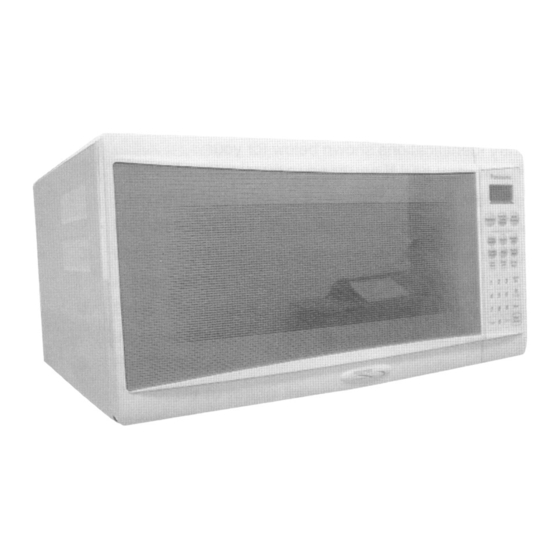
Panasonic Microwave Oven
PART NO. 541204
Specifications
Power Source:
Power Requirement:
Output (IEC705-88):
Microwave Frequency:
Timer:
Outside Dimensions:
Oven Cavity Dimensions:
Weight:
MICROWAVE OVEN
NN-S781
NN-S761
230V-240V AC Single Phase, 50Hz
1040W
1040W
1200W
1200W
2450MHz
30 min. / Stage (HIGH Power) -- 5 Stage Maximum
90 min. 99 sec. / Stage (Other Power Levels) - 5 Stage Maximum
21 7/8"(555mm)(W) x 19 9/16" (497mm)(D) x 11 15/16" (301 mm)(H)
16 7/16"(418mm)(W) x 18 1/2" (470mm)(D) 9"(228mm) (H)
36 lbs / 16.5kg
Output power: IE 705-88 Test Procedure
Specifications subject to change without notice.
QPQ
Australia
BF
NN-S781
NN-S761
NN-S751
NN-T791
NN – T791SF QPQ
NN-S751
1040W
1200W
WF
SF
NN-T791
1040W
1200W
599251
Advertisement
Table of Contents

Related Manuals for Panasonic NN-S781

Summary of Contents for Panasonic NN-S781
- Page 1 Panasonic Microwave Oven Australia NN-S781 NN-S761 NN-S751 NN-T791 PART NO. 541204 MICROWAVE OVEN NN – T791SF QPQ Specifications NN-S781 NN-S761 NN-S751 NN-T791 Power Source: 230V-240V AC Single Phase, 50Hz Power Requirement: 1040W 1040W 1040W 1040W Output (IEC705-88): 1200W 1200W 1200W...
- Page 2 MANUAL 599251...
-
Page 3: Precautions To Be Observed Before And During Servicing To Avoid Possible Exposure To Excessive Microwave Energy
MANUAL 599251 WARNING This service information is designed for experienced repair technicians only and is not designed for use by the general public. It does not contain warnings or cautions to advise non-technical individuals of potential dangers in attempting to service a product. Products powered by electricity should be serviced or repaired only by experienced professional technicians. -
Page 4: Inverter Warning
MANUAL 599251 DANGER OF HIGH VOLTAGE AND HIGH TEMPERATURE (HOTILIVE) OF THE INVERTER POWER SUPPLY INVERTER WARNING This Inverter board looks like a regular PCB. However, this PCB drives the magnetron tube with extremely high voltage and high current. NEW HV IT HAS Very high voltage and high current circuits. - Page 5 MANUAL 599251...
- Page 6 MANUAL 599251 SCHEMATIC DIAGRAM – (QPQ)
-
Page 7: Measurements And Adjustments
MANUAL 599251 MEASUREMENTS AND ADJUSTMENTS WARNING For continued protection against radiation hazard, replace only with identical replacement parts (For touch models Part No. A6142-1450, Type No. V- 16G-3C26-M for Primary latch switch Part No. A61425180AP, Type No. L-3C2-2 for Secondary latch switch and Part No. - Page 8 MANUAL 599251 Place the beaker on the centre of glass cook plate. Set the oven for High power and heat it for exactly one minute. Stir the water again and read the temperature of the beaker (recorded as T2). The normal temperature rise at High power for each model is shown in the table.
-
Page 9: Procedure For Measuring Microwave Energy Leakage
MANUAL 599251 PROCEDURE FOR MEASURING MICROWAVE ENERGY LEAKAGE WARNING WARNING Check for radiation leakage after every servicing. Should AVOID CONTACTING ANY HIGH VOLTAGE PARTS. the leakage be more than 2mW/cm after repairing or replacing any radiation safety device, keep a written record for future reference, the leakage reading must be recorded on the service repair ticket while in the customer's home. - Page 10 MANUAL 599251 WARNING: Avoid contacting any high voltage parts. Measurements with a fully assembled oven. After all components, including outer panel are fully assembled, measure for radiation leakage around the door periphery, the door viewing window, the exhaust opening and air inlet openings, Record keeping and notification after measurement After any adjustment or repair to a microwave oven, a leakage reading must be taken.
-
Page 11: Exploded View
MANUAL 599251 EXPLODED VIEW... -
Page 12: Parts List
MANUAL 599251 PARTS LIST NOTE: When ordering replacement part(s), please use part number(s) shown in this part list. Do not use description of the part. Important safety notice. Components identified by mark have special characteristics important for safety. When replacing any of these components use only the manufacturer’s specified parts. - Page 13 MANUAL 599251 F0922000EK CUSHION RUBBER F0922000BJ CUSHION RUBBER F0902000AA CUSHION RUBBER T791SF...
-
Page 14: Door Assembly
MANUAL 599251 DOOR ASSEMBLY Part Number Part name & Remarks description F3018-1200 DOOR KEY A F30014W00BAP DOOR A S761BF, S751BF F30014W00HAP DOOR A S781WF, S761WF, S751WF B301A4W70CP DOOR A (U) UNIT T791SF F302K4W00AP DOOR E (U) F30214000AP DOOR KEY SPRING F30854W00AP DOOR C F31454W00AP... -
Page 15: Wiring Materials
MANUAL 599251 WIRING MATERIALS Part Number Part name & description Remarks F030A4W00QP LEAD WIRE HARNESS F030E4W00CP H.V. LEAD WIRE... -
Page 16: Escutcheon Base Assembly
MANUAL 599251 ESCUTCHEON BASE ASSEMBLY Part Number Part name & description Remarks F603L5B00QP D.P. CIRCUIT S780WF, S760BF/WF F603L5B10QP D.P. CIRCUIT S750BF/WF F603L5B20QP D.P. CIRCUIT T790SF F603L5B50QP D.P. CIRCUIT RTL(W/COMPONENT) S780WF, S760BF/WF, S750BF/WF) F603Y4W00QP D.P. CIRCUIT RTL (W/COMPONENT) S781WF, S761BF/WF F603Y4W10QP D.P. - Page 17 MANUAL 599251 S751BF/WF F00075B00HQP NAME PLATE S781WF F00075B10BQP NAME PLATE S761BF F00075B10HQP NAME PLATE S761WF F00075B20BQP NAME PLATE S751BF F00075B20HQP NAME PLATE S751WF F00075B50SQP NAME PLATE T791SF B890L5B50SQP CONTROL PANEL (AU) T791SF...
-
Page 18: Packing And Accessories
MANUAL 599251 PACKING AND ACCESSORIES Ref. Part No. Part name & Description Remarks F00035B00QP INSTRUCTION MANUAL F01025B00HQP PACKING CASE,PAPER S781WF F01025B10BQP PACKING CASE,PAPER S761BF F01025B10HQP PACKING CASE,PAPER S761WF F01025B20BQP PACKING CASE,PAPER S751BF F01025B20HQP PACKING CASE,PAPER S751WF F01025B5SQP PACKING CASE,PAPER T791SF F01044W00AP UPPER FILLER F01054W00AP... - Page 19 MANUAL 599251 INVERTER BOARD PARTS LIST Ref. No. Part No. Part name & Description Pcs / Remarks C701 ECWF5104N300 CAPACITOR 0.1µ F, 500VDC C702 ECQE2405T847 POLYESTER 4µF, 250VDC CAPACITOR C703 ECWF5454N300 FILM CAPACITOR 0.45µF, 500VDC C704, C705 ECWH30822JUA FILM CAPACITOR 8200PF, 3KVDC CN701 AEEMXH00703W...
- Page 20 MANUAL 599251 DIGITAL PROGRAMMER CIRCUIT (NN-S781, NN-S761) SCHEMATIC DIAGRAM...
- Page 21 MANUAL 599251...
- Page 22 MANUAL 599251 DIGITAL PROGRAMMER CIRCUIT (NN-S751) SCHEMATIC DIAGRAM...
- Page 23 MANUAL 599251...
- Page 24 MANUAL 599251 NN-S751 - DIGITAL PROGRAMMER CIRCUIT PARTS LIST REF No. PART No. DESCRIPTION REMARKS C40-48,330 AECU85C102KK CHIP CAPACITOR 1000PF/50V/20% C100, 340 AECU85F103ZK CHIP CAPACITOR 0.01µF/50V/ -20%+80% C12, 290, 291, C300, 301 AECU82F104ZK CHIP CAPACITOR 0.01µF/25V/ -20%+80% R50-58, 101, 102, 103, 441 AERJ3GSYJ102 CHIP RESISTOR R221 AERJ3GSYJ103...
- Page 25 MANUAL 599251 NN-S781, NN-S761 - DIGITAL PROGRAMMER CIRCUIT PARTS LIST REF No. PART No. DESCRIPTION REMARKS C40-48, 330 AECU85F103ZK CHIP CAPACITOR 1000PF/50V/20% C100, 340, 484 AECU85C102KK CHIP CAPACITOR 0.01µF/50V/ -20%+80% C481 AECU85F473ZK CHIP CAPACITOR 0.047µF/50V/ -20%+80% C12, 290, 291, C300, 301...