Advertisement
Quick Links
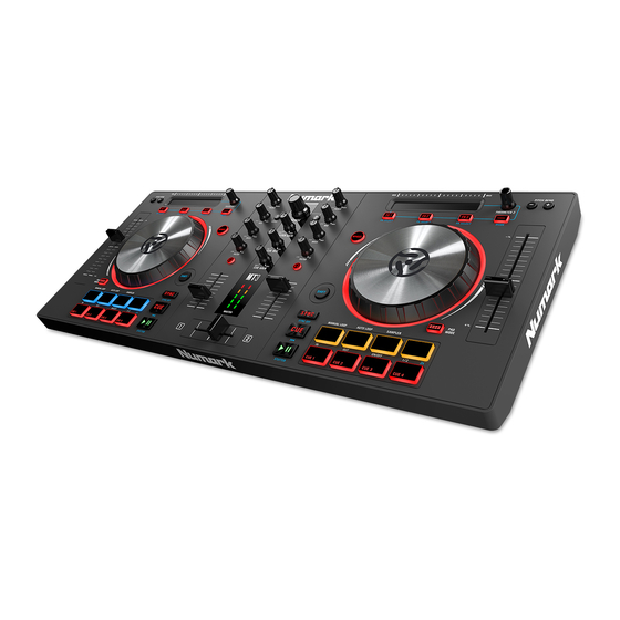
FUNCTION
1. Browser Knob ----------------Rotate this knob to cycle through folders and tracks. Press the Knob To cycle between the
2. Master Gain --------------------Adjusts the master volume in the software.
3. Cue Mix ------------------------Adjusts the software's audio output to the headphones, mixing between the cue output and the
4. Cue Gain -----------------------Adjusts the volume for headphone cueing in the software.
5. Load ----------------------------Press one of these buttons while a track is selected to assign it to Deck 1 and 2,respectively, in
6. High EQ -----------------------Controls the treble frequencies for the individual channels.
7. Mid EQ-------------------------Controls the mid range frequencies for the individual channels.
8. Low EQ ------------------------Controls the bass frequencies for the individual channels.
9. Filter ----------------------------Adjusts the amount of the filter effect. Turning the knob left and right will produce a
10. Cue/PFL ----------------------Sends pre-fader audio to the Cue Channel for headphone monitoring.
11. Channel Volume-------------Adjusts the volume of the individual channels in the software.
12.Cross Fader--------------------Controls the blend between the two decks.
13. Platter/Jog---------------------This capacitive, touch-sensitive jog wheel controls the audio when the wheel is touched and
14. Pad Mode---------------------This is used to change the operation of the top 4 performance pads.
15.Play/Pause---------------------Starts and suspends playback. Hold Shift + Play/Pause to stutter the track from the last set cue
16. Performance Pads-----------The top row of pads is used to trigger autoloop points. The bottom row of pads is used to
SERVICE MANUAL
SPECIFICATION
Crates and Library.
master mix output.
the software.
Low Pass Filter or High Pass Filter.
moved. When the Wheel button is not active, use the jog wheel to bend the pitch of the track.
When the Wheel button is active, use the jog wheel to grab and move the audio, "scratching"
the track as you would with a vinyl record. You can also grab the non-touch-sensitive outer
wheel to bend the pitch of the track.
point. If a cue point has not been set, the play head will return to the start of the track.
trigger
Cue points. If a Cue point has not already been set for the loaded track, this control will mark
the
Cue point. If a Cue point has already been set, this control will jump to Cue point.
MODEL: MIXTRACK3
Advertisement

Related Manuals for Numark MIXTRACK3


Summary of Contents for Numark MIXTRACK3
- Page 1 SERVICE MANUAL MODEL: MIXTRACK3 SPECIFICATION FUNCTION 1. Browser Knob ----------------Rotate this knob to cycle through folders and tracks. Press the Knob To cycle between the Crates and Library. 2. Master Gain --------------------Adjusts the master volume in the software. 3. Cue Mix ------------------------Adjusts the software’s audio output to the headphones, mixing between the cue output and the master mix output.
-
Page 2: Audio Output
AUDIO OUTPUT LINE OUT OUTPUT LEVEL---------------1.3 ± 0 .2Vms(1KHz 0dB) S/N RATIO-----------------------MORE THAN 80dB FREQUENCY RESPONSE---20Hz~20KHz ± 3 dB CHANNEL SEPARATION---MORE THAN 80dB HARMONIC DISTORTION--LESS THAN 0.03%... - Page 3 1. REMOVAL OF THE BOTTOM CHASSIS. (Fig1) (A) TAKE OUT THE 5 PCS VR CAP AND 14 PCS KNOB (B) TAKE OUT THE 22 PCS SCREWS (C) TAKE OUT THE BOTTOM CHASSIS Fig.1 2. REMOVAL PCB ASSEMBLY. (Fig2) (A) TAKE OUT THE 3 PCS SCREWS AND USB PCB ASSEMBLY, THEN TAKE OUT THE 1PCS CONNECTOR (B) TAKE OUT THE 5 PCS SCREWS AND MAIN PCB ASSEMBLY, THEN TAKE OUT THE 4PCS CONNECTOR (C) TAKE OUT 6 PCS SCREWS AND 2 PCS SIGNAL PLATE (D) TAKE OUT THE 22 PCS SCREWS, THEN TAKE OUT THE LEFT/RIGHT FUNCTION PCB ASSEMBLY AND...
- Page 10 NKCDMAR01~09 BOM DESCRIPTION LEVEL 0.1 CA040218002 Usb Cable 1.8M A/B Black 0.1 ERE75 E Ring 5mm 0.1 FFC2210000501 FFC 22Pin Pitch:1.0mm Length:1 0.1 FFC3210000501 FFC 32P Pitch:1.0mm Length:50m 0.1 GEMAR100 Download Card 0.1 LAC22MAR1035 Serial Number Label 0.1 LAC53MAR1002 Warning Label 0.1 LAC62MAR1012 Bar Code Label(CODE 39)(01) 0.1 LAC62MAR1013...
- Page 11 0.1 PT11106496 Knob(LRG) 0.1 PT11106497 Knob(MEDV) 0.1 PT11106529 VR Cap 0.1 PT11106555 Light Pipe(5) 0.1 PT1110657402 Knob Assembly 0.1 PT11106590 Lamp 0.1 PT11106593 Knob(MED) 0.1 PT111078002 Wheel(Black Painting) ..2 PT1110780 Wheel ...3 LAC67MAR1008 Label ...3 MT1105582 Jog Axis 0.1 PT113026501 Cabinet (Painting &...
- Page 12 ...3 RS100K10F03 RESISTOR 100K 1% SMD 0603 R153 ...3 RS47K510F03 RESISTOR 47.5K 1% SMD 0603 R13,155 ...3 SWDC11B2021431 Switch Rotational Encode 20Pul ENC1 ...3 SWEVQ11L05R Switch Tact 5mm 160g Horizonta SW1~4 ...3 TE612000402 4P CONNECTOR (TE1) ...3 VRR10301701 VARIABLE 10KB VR6,15,16 ...3 VRR10301704 Poltertiomaeter Rotary Volume...
- Page 13 ...3 CS470J5005NPO CCAP SMD 47pF/50V 5% 0805 NPO C514 ...3 CS473K5005X7R CCAP SMD 0.047uF/50V 10% 0805 C503 ...3 DICM1213A01SO Diode ESD Protection Arrays CM D500,501 ...3 DIEN1N4148WSM Diode SMD D502,503 ...3 DIPH574 Photo Sensor SEN500,501 ...3 FCN1T1000401 FCN Up Touch ZIF SMD Pitch=1.0mm FCN500 ...3 FCN1T1003201 FCN Down Touch ZIF Pitch:1.0mm...
- Page 14 ...3 RS001K10F03 RESISTOR 1K 1% SMD 0603 R814~819 ...3 RS003310F03 RESISTOR 33 1% SMD 0603 R807~812 ...3 RS010K10F03 RESISTOR 10K 1% SMD 0603 R800,801 ...3 RS022010F03 RESISTOR 220 1% SMD 0603 R820~823,825,826,828,829 ...3 RS047010F03 RESISTOR 470 1% SMD 0603 R824,827,830,831 ...3 SWEVQ11L05R Switch Tact 5mm 160g Horizonta SW808~810...
- Page 15 D+5V D+5V FDC6306P L+5V FDC6306P TLV1117LV33 A+3.3V Vout SW+3.3V D+3.3V R153 MBT4403 MBT4403 C124 FROM R-PAD PCB FCN800 100K VR+3.3V 0.1uF 3.3K R6 4.7uF 0.1uF 4.7uF 0.1uF 0.1uF FCN1 R154 WHEEL+3.3V R155 R156 D+5V C123 RESET ENCODE 47.5K DGND SW+3.3V 47.5K(DNS) 47.5K(DNS) 47.5K...
- Page 16 D200 NUP2201MR6 VBUS. Vbus UGND FROM MAIN PCB CN1 UGND USB JACK C202 USB200 0.1uF TE201 C203 0.1uF DGND. PGND. R200 NKCD\NKCE USB Title: Size Number PC14C030B Revision Date : 2015.01.15 Sheet File Name: Design By : Approval Check Design DATE Description...
- Page 17 VR+3.3V D+5V AGND VR+3.3V R125 LED5 D+5V 0.1uF 10uF 0.1uF Treble-L R113 LED16 Filter-L D+5V Bass-L Mid-L LED-SAMPLE-L HP-L VR17 74HC4051 AGND R114 DGND LED_DATA1 LED-FX1-L PGND PGND AGND LED_EN LED-FX2-L 0.1uF R115 FSR-L OUT/IN LED_RC1 LED-FX3-L AGND R116 PITCH-L LED_CLK1 LED-WHEEL-L AGND...
- Page 22 VR+3.3V C300 C301 0.1uF 10uF TO FSR VR300 D300 10KB D301 PGND R300 C302 R301 R302 C303 C304 0.1uF VR CIRCUIT FCN300 47nF 0.1uF PGND PGND PITCH-L VR+3.3V PGND PGND PGND FSR-L JOGL-1 JOGL-2 BEAT-L-2 BEAT-L-1 Fun-Key CIRCUIT VR+3.3V TOUCH-L SW+3.3V C305 C306...
- Page 23 VR+3.3V C500 C501 0.1uF 10uF TO FSR VR500 D500 10KB D501 PGND R500 1K-0805 C502 R501 R502 C503 C504 0.1uF VR CIRCUIT FCN500 47nF 0.1uF PGND PGND PITCH-R VR+3.3V PGND PGND PGND FSR-R JOGR-1 JOGR-2 BEAT-R-2 BEAT-R-1 Fun-Key CIRCUIT VR+3.3V TOUCH-R SW+3.3V WHEEL+3.3V...
- Page 27 KEY_SCAN0 KEY_SCAN1 KEY_SCAN2 KEY_SCAN3 KEY_SCAN4 KEY_SCAN5 KEY_SCAN6 KEY_SCAN7 PAD1 PAD2 PAD3 PAD4 PAD5 PAD6 PAD7 PAD8 SW700 SW701 SW702 SW703 SW704 SW705 SW706 SW707 D700 D701 D702 D703 D704 D705 D707 D709 R700 SW+3.3V 1N4148 1N4148 1N4148 1N4148 1N4148 1N4148 1N4148 1N4148 KEY_D0...
- Page 28 KEY_SCAN0 KEY_SCAN1 KEY_SCAN2 KEY_SCAN3 KEY_SCAN4 KEY_SCAN5 KEY_SCAN6 KEY_SCAN7 PAD5 PAD1 PAD6 PAD2 PAD7 PAD3 PAD8 PAD4 SW804 SW800 SW805 SW801 SW806 SW802 SW807 SW803 D800 D801 D802 D803 D804 D806 D807 D809 R800 SW+3.3V 1N4148 1N4148 1N4148 1N4148 1N4148 1N4148 1N4148 1N4148 KEY_D2...