Table of Contents
Advertisement
Quick Links
ALL phases of this installation must comply with NATIONAL, STATE AND LOCAL CODES
IMPORTANT — This Document is customer property and is to remain with this unit. Please return to service informa-
tion pack upon completion of work.
These instructions do not cover all variations in sys-
tems nor provide for every possible contingency to be
met in connection with installation. All phases of this
installation must comply with NATIONAL, STATE AND
LOCAL CODES. Should further information be desired or
should particular problems arise which are not covered suf-
ficiently for the purchaser's purposes, the matter should be
referred to your installing dealer or local distributor.
A. GenerAl
WArnInG
!
This information is intended for use by individuals pos ses
s ing adequate backgrounds of electrical and mechanical
experience. Any attempt to repair a central air condition ing
product may result in personal injury and or property dam
age. The manufacturer or seller cannot be respon sible for
the interpretation of this information, nor can it assume any
liability in connection with its use.
NOTICE:
Trane has always recommended installing Trane approved
matched indoor and outdoor systems.
The benefits of installing approved matched systems are
maximum efficiency, optimum performance and best overall
system reliability.
WArnInG
!
These units use r410A refrigerant which operates at 50 to
70% higher pressures than r22. Use only r410A approved
service equipment. refrigerant cylinders are painted a rose
color to indicate the type of refrigerant and may contain a dip
tube to allow for charging of liquid refrigerant into the sys
tem. All r410A systems use a POe oil that readily absorbs
moisture from the atmosphere. To limit this hygroscopic ac
tion, the system should remain sealed whenever possible. If
a system has been open to the atmosphere for more than 4
hours, the compressor oil must be replaced. never break a
vacuum with air and always change the driers when opening
the system for component replacement. For specific han
dling concerns with r410A and POe oil, reference retrofit
Bulletin SSCAPG011en.
Check for transportation damage after unit is uncrated. Report
promptly, to the carrier, any damage found to the unit.
To determine the electrical power requirements of the unit, re-
fer to the nameplate of the unit. The electrical power available
must agree with that listed on the nameplate.
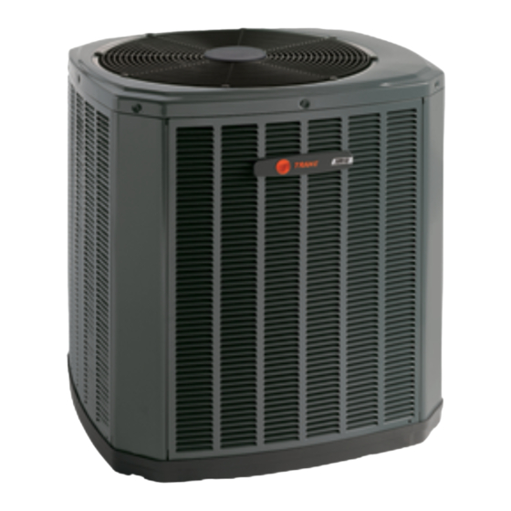
Installer's Guide
Condensing Units
4TWr5
UnIT COnTAInS r410A reFrIGerAnT!
R-410A OPERATING PRESSURE EXCEEDS THE
LIMIT OF R-22. PROPER SERVICE EQUIPMENT IS
REQUIRED. FAILURE TO USE PROPER SERVICE
TOOLS MAY RESULT IN EQUIPMENT DAMAGE OR
PERSONAL INJURY.
1
B. lOCATIOn And PrePArATIOn
OF The UnIT
Cold Climate Considerations
The Heat Pump has been designed and manufactured to with-
stand and operate in severe winter conditions. However, there
are precautionary steps which should be taken at the time of
installation which will help assure the efficient operation of the
unit. It is recommended that these precautions be taken
for units being installed in areas where snow accumula-
tion and prolonged below freezing temperatures occur.
1. Units should be elevated three (3) to twelve (12) inches
above the pad or roof top, depending on local weather. This
additional height will allow drainage of snow and ice
(melted during defrost cycle) prior to its refreezing. This
reduces the chance of ice build-up around the unit which
occurs when unit is not elevated. Ensure that drain
holes in unit base pan are not obstructed prevent-
ing draining of defrost water.
CAUTIOn
!
ServICe
USE ONLY R-410A REFRIGERANT AND
APPROVED POE COMPRESSOR OIL.
Single Unit Installation
1' Behind
18BC76d12
5' Above
Unrestricted
3'
Advertisement
Table of Contents

Related Manuals for Trane 4TWR5018E


Summary of Contents for Trane 4TWR5018E
- Page 1 5’ Above Unrestricted liability in connection with its use. NOTICE: Trane has always recommended installing Trane approved matched indoor and outdoor systems. The benefits of installing approved matched systems are maximum efficiency, optimum performance and best overall system reliability.
- Page 2 The liquid line valve is not a back seating valve (see (the position of the * denotes the latest revision number). WARNING below). 8. Locate and install indoor coil or air handler in accordance with instruction included with that unit. 18-BC76D1-2 © 2009 Trane...
- Page 3 Installer’s Guide with dry nitrogen to 350-400 psi. Use soap bubbles or other lIqUId lIne ServICe vAlve leak-checking methods to see that all field joints are leak-free! If not, release pressure; then repair! SySTeM evACUATIOn NOTE: Since the outdoor unit has a refrigerant charge, the gas and liquid line valves must remain closed.
-
Page 4: Electrical Connections
Installer’s Guide F. deFrOST COnTrOl NOTE: A 3/16" Allen wrench is required to open liquid line service The demand defrost control measures heat pump outdoor valve. A 1/4" Open End or Adjustable wrench is required to ambient temperature with a sensor located outside the out- open gas line valve. -
Page 5: Typical Field Hookup Diagrams
Installer’s Guide TyPICAl FIeld hOOkUP dIAGrAMS Notes: 1. Be sure power supply agrees with equip- ment nameplate. 2. Power wiring and grounding of equipment must comply with local codes. 3. Low voltage wiring to be No. 18 AWG minimum conductor. 4. -
Page 6: Compressor Startup
ChArGInG ChArT indoor and outdoor systems. ° DESIGN SUBCOOLING ( LIQUID All Trane split systems are AHRI rated with only TXV indoor sys- TEMP tems. ° LIQUID GAGE PRESSURE (PSI) The benefits of installing approved indoor and outdoor split systems are maximum efficiency, optimum performance and the best overall system reliability. - Page 7 Use Design Subcool Value from Table Subtract 10 psig from S.C. Table Pressure TOTAL REFRIGERANT LINE LENGTH (FEET) 4TWr5 OUTlIne drAWInG nOTe: All dIMenSIOnS Are In MM (InCheS). MOdelS BASe 4TWR5018E 841 (33-1/8) 946 (37-1/4) 870 (34-1/4) 152 (6) 98 (3-7/8) 219 (8-5/8)
-
Page 8: Mounting Hole Location
..........[ ] 7. Indoor coil drain line drains freely. Pour water into drain pan .............. [ ] Trane has a policy of continuous product and product data improvement and it reserves the right to change Trane design and specifications without notice.