Table of Contents
Advertisement
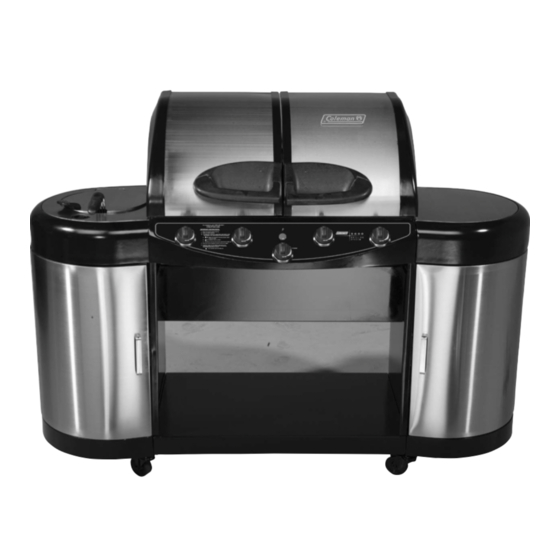
Gas Barbecue
Use, Care & Assembly Manual
With Grill Lighting Instructions
5600 LP Gas Series
5610 Natural Gas Series
ASSEMBLER/INSTALLER:
Leave these instructions with the consumer.
CONSUMER/USER:
Read all instructions and keep in a safe place for future reference.
For Outdoor Use Only
www.coleman.com
I I M M P P O O R R T T A A N N T T
Read this manual carefully before assembling,
using or servicing this grill. Keep this manual for
future reference. If you have questions about
assembly, operation, servicing or repair of this
grill, please call Coleman at 1-800-835-3278 or
C E R T I F I E D
®
®
TDD: 316-832-8707. In Canada call
1-800-387-6161.
Advertisement
Table of Contents

Related Manuals for Coleman 5600 Series


Summary of Contents for Coleman 5600 Series
- Page 1 Keep this manual for future reference. If you have questions about assembly, operation, servicing or repair of this grill, please call Coleman at 1-800-835-3278 or C E R T I F I E D ®...
-
Page 2: Table Of Contents
• NEVER place more than 15 pounds on a side table or a side burner. DO NOT lean on grill. (Fig. 5) • NEVER use charcoal briquettes or lighter fluid in a gas grill. (Fig. 6) • Grill is hot when in use; to avoid burns, DO NOT touch any hot grill surface. -
Page 3: General Installation
General Safety Information cont. General Installation • Installation must conform with local codes or, in the absence of local codes, with either the National Fuel Gas Code, ANSI Z223.1 (USA), CAN/CGA-B149.1, Natural Gas Installation Code or CAN/CGA-B149.2, Propane Installation Code (Canada). To check local codes, see your local L.P. -
Page 4: Electrical Attachments
L.P. gas is heavier than air and tends to collect in low areas. It is important that there are no leaking connections on your gas grill that could cause a fire or explosion (see “LEAK TESTING”, Pg. 32). -
Page 5: L.p. Gas Cylinder
Do not use another hose and regulator assembly other than the one supplied with the grill or a Coleman replacement pressure regulator assembly. The pressure regulator and hose assembly provided is factory set at an outlet pressure of 11 inches water column (1/2 psi). -
Page 6: Filling And Purging Type 1 L.p. Gas Cylinders
Transporting the Cylinder WARNING Handle a full cylinder with care. Gas is under high pressure. DANGER • NEVER store a spare L.P. gas supply cylinder under the grill body or inside grill enclosure or in the vicinity of any heat producing appliance. (Fig. 12) •... -
Page 7: Assembly/Set Up
Assembly/Set up Remove components from package. Hardware Blister Pack Firebox Left Fryer Assembly Fryer Grease Fryer Heat Shield Left Base 9-Volt Battery Left Panel Rear Panel Door Left Magnets Door Rear Trim Plate Side Table Cart Spacer Cart Spacer Center Right Base Base... - Page 8 NOTE: Use a large piece of cardboard or a ground cloth to protect the painted finish on the grill. NOTE: The base pieces are assembled up-side- Step down in this step. Hardware shown actual size (TN) M6 x 15mm Screw (8) Qty.
- Page 9 Carefully turn the assembly Right-Side-Up. Engage the Locking Step Casters to prevent movement during the rest of the assembly process. 2-A. Assemble the Cylinder 2-B. Assemble the Cylinder Hardware shown actual size (VP) Self Tapping Screw (1) Qty. Cylinder Support Retaining Bolt to the Hardware shown actual size Cylinder Support.
- Page 10 Assemble two Cart Spacers to the Grill Cart. Step Cart Spacer View of Grill from Rear View of Grill from Rear TN (x8) Cart Spacer Cart Spacers Hardware shown actual size (TN) M6 x 15mm Screw (8) Qty. 4-A. Assemble two Cart Spacers between the Left and Right Panels using eight Screws (TN).
- Page 11 Install Rear Panels. Hardware shown actual size Step Rear Panel 5-A. Assemble two Rear Panels to the cart assem- bly using eight Screws (TN). NOTE: The Rear Panels are identical. Align the square holes on the Rear Panel with the tabs and push down to install the panels.
- Page 12 Assemble Firebox to the Grill Cart. NOTE: A second person is Step needed when aligning the Firebox to the Grill Cart. 7-A. Carefully place the Firebox onto the Cart Assembly. Do not damage the Electrical Wires (see Fig. 7-B and 7-C). The Electrical Wires must be routed through the openings near the front and back of the Firebox.
- Page 13 NOTE: In Fig. 8-A and 8-B, the Step Cart Spacer is not illustrated. TN (x2) DY (x2) Flange on Right Side Panel 8-B. Fasten the left side of the Firebox to the Grill Cart with two Flat Washers (DY) and two Screws (TN). Tighten all fasteners.
- Page 14 NOTE: The Grill Lids should be opened for Step 9. Assemble Right Side Table to Step the Grill. Right Side Firebox Table Right Rear Panel Hardware shown actual size (TN) M6 x 15mm Screw (4) Qty. 9-A. Raise the Grill Lids. Place the Right Side Table against the Firebox and on top of the Right Rear Panel.
- Page 15 Assemble Right Side Table to the Grill (continued). Step 10-A 10-C DY (x2) View of Grill from Rear Hardware shown actual size (TN) (DY) M6 x 15mm Screw M6 Flat Washer (4) Qty. (2) Qty. 10-A. LOOSELY assemble two additional Screws (TN) and two Flat Washers (DY) through the Firebox into the Right Side Table at the rear of the grill.
- Page 16 NOTE: The Grill Lids must be opened for Step 11. Assemble Left Fryer Step Assembly to the Grill. 11-A Left Fryer Assembly Left Rear Panel 11-B Hardware shown actual size (TN) M6 x 15mm Screw (1) Qty. 11-A. Raise the Grill Lids. Place the Left Fryer Assembly against the Firebox and on top of the Left Rear Panel.
- Page 17 Assemble Left Fryer Assembly to the Grill (continued). Step 12-A 12-C View of Grill from Rear Hardware shown actual size (TN) (DY) M6 x 15mm Screw M6 Flat Washer (4) Qty. (2) Qty. 12-A. LOOSELY assemble two additional Screws (TN) and two Flatwashers (DY) through the Firebox into the Left Fryer Assembly at the rear of the grill.
- Page 18 Step 13-A Fuel Hose from Fryer Assembly 13-A. Assemble the Fuel Hose Fitting from the Grill to the Fryer Assembly. WARNING: During assembly of grill and when attaching or replacing the L.P. gas cylinder, insure that the gas supply hose is free of kinks and/or damage and is at least 3”...
- Page 19 Assemble the Electrode Wire to the Electrode Tip on the Side Fryer. Step Assemble the Grease Pan below the Fryer Burner. 14-A Route the Electrode Wire through the slot in the Electrode Tip 14-A. Attach the Electrode Wire to the Electrode Tip on the Side Fryer. 14-B Hooks 14-B.
- Page 20 Step 15-A Electrode 15-A. Assemble Fryer Heat Shield. NOTE: Place the Fryer Heat Shield between the Fryer Panel and the Flexible Fuel Hose. Do not pinch Electrode Wire. Engage the two tabs on the Heat Shield downward into the rectangle holes. 15-B Fryer Heat...
- Page 21 Step 16-A 16-A. Route the Back Burner Electrical Wire through the Wire Support. 16-C 16-C. Route the Main Burner Electrical Wires through the Wire Tie. Wrap the Wire Tie around the wire and secure in place. Route the Electrical Wires under the Right Side Table.
- Page 22 Assemble the electrode Wires and the Battery to the Electrode Module. Step 17-A 17-A. Firmly push the Electrode Wires into the Electrode Module. EST THE GNITER A SPARK SHOULD APPEAR AT ELECTRODE TIP F THE SPARK DOES NOT APPEAR HECK THE WIRE CONNECTIONS TO THE MODULE HECK PROPER...
- Page 23 Fasten the Rear Trim Plate to the Grill Cart. Step Hardware shown actual size (VP) Self Tapping Screw (2) Qty. 18-A FIREBOX 18-B 18-C REAR TRIM PLATE VP (x2) 18-C. View showing Rear Trim Plate properly installed. 18-A. Fasten the Rear Trim Plate to the Firebox with...
- Page 24 Fasten both Left and Right Doors to the Grill Cart. Attach the Tool Hook to the Step Right Door. 19-A LEFT DOOR (without Tool Hook Brackets) 19-B 19-B. Fasten the Right Door to the Grill Cart with four Flat Head Screws (XR). NOTE: Right Door has Tool Hook Brackets.
-
Page 25: Right Door
Fasten the Door Handles to the Doors. Attach the Tool Hook to the Step Right Door. NOTE: M4 x 5mm Screws are factory installed into the Handles. Hardware shown actual size (EZ) M4 X 5mm Screw (4) Qty. 20-A EZ (x2) RIGHT DOOR DOOR... - Page 26 21-B Heat Tents™ 21-B. Install four Heat Tents™ over the Burners. The Heat Tents™ are located using the alignment pins. 21-C Standard Power Grate Grates 21-C. Install four Cooking Grates with smooth surface down. Locate the Power Grates in the center positions. 21-D Warming Racks...
-
Page 27: Grease Pan
Assemble two Grease Cup Supports to the Grease Pan. Note: The Grease Pan is shown Step up-side-down during this step. Hardware shown actual size Self Tapping Screw 23-A VP (x4) Grease Support Grease Pan Note: Lip is up. 23-A. Attach the Grease Cup Support to the Grease Pan with two self-tapping screws (VP). - Page 28 Assemble the Motor Mount Bracket to the right outside of the Firebox. Step Assemble the Rotisserie to the Firebox. Hardware shown actual size (TN) M6 x 15mm Screw (2) Qty. 25-A UO (x2) Motor Mount Bracket 25-A. Attach the Motor Mount Bracket to the metal side panel using two Screws (TN) and two Hex Nuts (UO).
- Page 29 25-E Push Button to Remove Rotisserie Handle 25-E. Remove Handle immediately after placing Rotisserie into the Firebox. Damage will occur if the Handle is not removed prior to cooking. CAUTION • DO NOT OPERATE THE GRILL WITH THE ROTISSERIE HANDLE ON THE SPIT ROD.
- Page 30 NOTE: Step 26 applies to you only if your grill is set up from the factory to use LP GAS. If your grill is set up from the factory to use NATURAL GAS, skip to Step 27. Attach an LP Cylinder to the Grill.
- Page 31 NOTE: Step 27 applies to you only if your grill is set up from the factory to use NATURAL GAS. If your grill is set up from the factory to use LP GAS, skip back to Step 26. Attach a NATURAL GAS line to the grill.
-
Page 32: Connecting Type 1 L.p. Gas Cylinders
2. Wash off soapy solutions with cold water and towel dry. 3. Stop a leak by tightening the loose joint, or by replacing the faulty part with a replacement part recommended by Coleman. DO NOT attempt to repair the cylinder valve if it should become damaged;... -
Page 33: Start-Up Check List
Fixing A Fuel Leak (cont.) CAUTION Inspect the gas supply hoses before each use. If there are cuts, damage, excessive abrasion or wear, replace the hoses prior to operating the appliance. During assembly of grill and when attaching or replacing the L. P. gas cylinder, insure that all gas supply hoses are free of kinks and/or damage and are at least 3"... -
Page 34: Lighting Main Burners
Lighting Main Burners Igniter Lighting 1. Turn on any or all main burner gas control knobs to high. (Fig. 19) 2. Press the igniter switch until the flame ignites. 3. If the flame does not immediately light, turn off control knobs and wait five minutes for gas to clear. -
Page 35: General Use And Correct Burner Flames
L.P. cylinder, cylinder valve, regulator, gas supply hose, burner valve(s) and burner(s). 5. If any of the above mentioned components are damaged, seek replacement from Coleman before operating the grill again. Locate your nearest service center by calling 1-800-835-3278. -
Page 36: Cooking Methods
Cooking Methods Direct Method: • The heat source is directly below the food. • Use for browning meat or cooking hot dogs and hamburgers, but check food frequently. • Use for skillet and stir-fry cooking, but limit the amount of oil and heat to be used. -
Page 37: Cleaning And Maintenance
Moving and Storage A collision with the grill, as with any metal object, could cause injury. Use care when moving a portable gas grill. Moving the grill: • Move grill slowly. DO NOT run with or pull the grill behind you;... -
Page 38: For Your Additional Safety
O.P.D. feature. For Your Additional Safety YOUR NEW GAS GRILL IS EQUIPPED WITH A TYPE 1 CONNECTION DEVICE WHICH HAS 3 SAFETY FEATURES: (SEE TYPE 1 CONNECTION ILLUSTRATION) 1. -
Page 39: Registration Card
¨ warranty. PROTECT YOUR PRODUCT: We will keep the model number and date of purchase of your new Coleman you refer to this information in the event of an insurance claim such as fire or theft. PROMOTE BETTER PRODUCTS: We value your input. Your responses will help us develop products designed to best meet your needs. - Page 40 Stainless steel material (if applies) Porcelain or stainless steel cooking grates Thank you for filling out this questionnaire. Your answers are important to us. Please check here [ ] if you prefer not to learn more about Coleman ® Outdoor Cooking Products or www.coleman.com.
-
Page 41: Recipes
Recipes Spice-rubbed spareribs Cooking time: 45 minutes to partial boil; 16-20 min- utes to grill 6 pounds baby back pork spareribs water to cover For the spice mixture: 2 Tb brown sugar 3 Tb paprika 1 Tb chili powder 1 tsp garlic powder 2 tsp black pepper 1 Tb Dijon mustard 1 Tb salt... - Page 42 Recipes Asian-flavored eggplant Cooking time: 8-10 minutes 2 large eggplant, peeled and sliced into 1/2 inch rounds 2 Tb olive oil For the sauce: 1 tsp grated ginger 3 cloves minced garlic 4 green onions, sliced thin 2 Tb soy sauce 1 Tb hoisin sauce 2 tsp sugar juice of one lime...
- Page 43 Recipes Lemongrass beef skewers with peanut dipping sauce Cooking time after marination: 4-5 minutes 2 pounds boneless sirloin For the Marinade: 3 cloves garlic, minced 2 stalks lemongrass, trimmed of tough outer layer, sliced (find in Asian markets) 2 Tb sugar 1 Tb soy sauce 3 Tb thai fish sauce (find in Asian markets) 1.5 inch thick slice fresh ginger, minced...
- Page 44 (see label on cylinder for cylinder manufacturer’s warranty) or the paint finish of the product. Coleman, at its option, will repair or replace this product or any component of the product found to be defective during the war- ranty period.