
Summary of Contents for LENCO BearCat
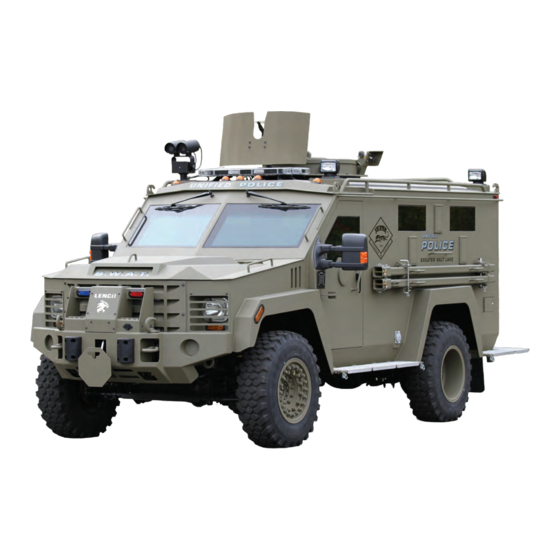
- Page 1 Lenco Bearcat operator & Maintenance ManuaL 10 Betnr Industrial Drive Pittsfield, MA 01201 USA Toll Free: 1-800-444-5362 PH: 413-443-7359 © Copyright 2016 Lenco Industries, Inc. All Rights Reserved.
-
Page 2: Table Of Contents
Table of Contents General Information Preface Scope Characteristics Pre-Operation Inspection Engine Battery Engine Coolant Fuel Transmission Transfer Case Engine Fluids Refrigerant Carbon Monoxide Brakes Wheels and Tires Jacks / Lifting Towing Doors Driving and Operating Fording Water Stowage / Cargo Gunner Hatch / Stand III General Vehicle Operation Restraint Systems... - Page 3 Multi-Point Inspection Opening and Closing the Hood Under Hood Overview Glass and Paint Care Maintenance Storage Cleaning Paint Care Tire Pressures / Wheel Torque Vehicle Lubrication Welding Precautions VII Lenco Armored Vehicles Contact Information Company Headquarters Customer Service Parts Department...
-
Page 4: General Information
General Information Preface: This Manual is written with regard to persons who will be operating or maintaining the Lenco BearCat. Operation of the Lenco BearCat without thoroughly reading this manual could result in vehicle damage or personal injury. Operators should familiarize themselves with the format and contents of this manual prior to operating/ maintaining the Lenco BearCat. -
Page 5: Pre-Operation Inspection
Pre-Operation Inspection Before operation of the Lenco BearCat perform a thorough inspection of the vehicle interior, exterior, and all of its components to ensure maximum protection for operator and crew. This inspection should include a visual as well as a physical inspection. -
Page 6: Fuel
Fuel Do not fill fuel tank while engine is running, do not over fill tank, and make sure fuel nozzle is grounded to filler neck to prevent sparks while fueling. Be alert at all times for the smell of fuel while operating vehicle. If fuel smell is detected shut down engine immediately. -
Page 7: Carbon Monoxide
R134a must not be mixed with air before being pressurized. When mixed with large quantities of air and pressurized R134a becomes combustible. Refrigerant evaporates quickly and can displace oxygen in the work area, and can cause suffocation. If a leak occurs avoid breathing refrigerant vapor and thoroughly ventilate work area before continuing service to HVAC system. -
Page 8: Jacks / Lifting
Jacks / Lifting Before lifting the vehicle, make sure it is parked on a level surface. Put the vehicle in park, set the emergency brake, and chock the wheels. Use hydraulic jack rated for 6 ton or more. Never work under a vehicle supported by only a jack or lifting device. Use properly rated jack stands under frame rails to properly support vehicle components during removal and installation procedures. -
Page 9: Fording Water
Avoid driving or parking on soft shoulders. Soft road shoulders can collapse. Vehicle can roll over causing severe injury or death to personnel. Wear restraint harnesses during vehicle operation. Check harnesses for damage before using. Adjust restraint harnesses properly for maximum protection. Fording Water Do not attempt to ford water deeper than 32 inches. -
Page 10: General Vehicle Operation
General Vehicle Operation Restraint Systems Front Air Bags Warning: Never place your arm or any objects over an airbag module. Placing your arm over a deploying airbag can result in serious arm fractures or other injuries. Objects placed on or over the airbag inflation area may cause those objects to be propelled by the airbag into your face and torso causing serious injury. -
Page 11: Front Seats
Turning the Passenger Airbag Back ON 1. Insert the ignition key and turn the switch to ON. 2. The PASS AIRBAG OFF light will briefly illuminate when the ignition is turned to on. This indicates that the passenger airbag is operational. The passenger side airbag should always be on (the PASS AIRBAG OFF light should not be illuminated) unless the passenger is a person who meets the requirements stated either in Category 1, 2 or 3 of the National Highway Traffic Safety Administration or Transport Canada deactivation criteria. -
Page 12: Steering Wheel
• Hold the steering wheel with your arms slightly bent • Bend your legs slightly so that you can press the pedals fully • Position the lap belts across your hips and position the shoulder strap over the center of your shoulder. Make sure that your driving position is comfortable and that you can maintain full control of your vehicle Seat restraints with visible abrasion or tearing must be replaced. -
Page 13: Instrument Cluster
Warning: Do not adjust the steering wheel while vehicle is moving. 1. Unlock the steering column. 2. Adjust the steering wheel to the desired position up/down in/out. 3. Lock the steering column. Instrument Cluster (6.8L V10 Gasoline) A. Engine Oil Pressure Gauge B. -
Page 14: Engine Oil Pressure Gauge
Instrument Cluster (6.7L V8 Diesel) A. Engine Boost Gauge Engine Oil Pressure Gauge Engine Oil Pressure Gauge indicates engine oil pressure. The needle should stay in the normal operating range (centered between L and H). If the needle falls below the normal range, stop the vehicle, turn off the engine and check the engine oil level. -
Page 15: Fuel Gauge
Fuel Gauge Note: The fuel gauge may vary slightly when your vehicle is moving or on a gradient. Switch the ignition on. The fuel gauge will indicate approximately how much fuel is left in the fuel tank. The arrow adjacent to the fuel pump symbol indicates on which side of your vehicle the fuel filler door is located. The needle should move toward F when you refuel your vehicle. -
Page 16: Switching Off The Engine
Do not turn the key to the start position until the glow plug pre-heat indicator turns off. When the glow plug pre-heat indicator turns off, turn the key to the start position and release the key as soon as the engine starts. -
Page 17: Cold Weather Operation
Cold Weather Operation (6.7L V8 Diesel) The use of the factory engine block heater assists in engine starting in extreme cold ambient temperatures. The engine block heater plug is located behind the front bumper on the passenger side frame rail. Note: The heater is most effective when outdoor temperatures are below 0°F (-18°C). - Page 18 Note: Do not use water, solvents, or hard brushes to clean the air filter. Warning: To reduce the risk of vehicle damage and/or personal burn injuries do not start your engine with the air filter removed and do not remove it while the engine is running. In order to operate the engine in temperatures of 32°F (0°C) or lower, read the following instructions: •...
-
Page 19: Fuel And Refueling
In order to operate the engine in temperatures of 32°F (0°C) or lower, read the following instructions: • Make sure that the batteries are of sufficient size and are fully charged. Check other electrical components to make sure they are in optimum condition •... -
Page 20: Esof 4Wd System
• Avoid inhaling fuel vapors. Inhaling too much fuel vapor of any kind can lead to eye and respiratory tract irritation. In severe cases, excessive or prolonged breathing of fuel vapor can cause serious illness and permanent injury. • Avoid getting fuel liquid in your eyes. If you splash fuel in your eyes, remove contact lenses (if worn), flush with water for 15 minutes and seek medical attention. - Page 21 4WD Indicator Lights Momentarily illuminates when 2H is selected 4x4 HIGH Continuously illuminates when 4H is selected 4x4 LOW Continuously illuminates when 4L is selected CHECK 4x4 Displays when a 4x4 fault is present Using the Electronic Shift-On-the-Fly 4WD System Use the rotary control located on the instrument panel to select the following: 2H (2WD) Sends power to the rear wheels only and should be used for street and highway driving.
-
Page 22: Msos 4Wd System
Shifting Between System Modes Note: Momentarily releasing the accelerator pedal while performing a shift will improve engagement/disengagement times. Note: Do not perform this operation if the rear wheels are slipping. Note: Some noise may be heard as the system shifts or engages; this is normal. Note: 4x4 High mode is not intended for use on dry pavement. - Page 23 4WD Indicator Lights Note: When a 4x4 system fault is present, the system will typically remain in whichever 4x4 mode was selected prior to the fault condition occurring. It will not default to 4x2 in all circumstances. When this warning is displayed, have your vehicle serviced by an authorized dealer.
- Page 24 4H (4x4 High) Used for extra traction such as in snow or icy roads or in off road situations. This mode is not intended for use on dry pavement. N (Neutral) Only used when towing the vehicle. No power to front or rear wheels. 4L (4x4 Low) 4L uses extra gearing to provide maximum power to all four wheels at reduced speeds.
-
Page 25: Tow / Haul
5. If shifting to 2H (2WD), with the vehicle at a complete stop, disengage the locking hubs (optional) by rotating the hub lock control from LOCK to FREE. Warning: Do not leave the vehicle unattended with the transfer case in the N (Neutral) position. Always set the parking brake fully and turn off the ignition when leaving the vehicle. -
Page 26: Exterior Handles
Warning: When entering the cabin of the vehicle use the three points of contact system. Use hand rails for pulling yourself into the vehicle. Operation of Exterior Handles To open doors from the vehicle exterior depress the door actuator located on the exterior door handle. Use the handle to pull the door open. -
Page 27: Striker Pins
Door Latch Maintenance Striker Pins Note: Check all Striker Pins every 2000 miles or if door lock function is impaired. Striker pins may become loose causing the door to close improperly. It is important to adjust Striker pins so the outside of the doors align properly against the exterior walls. -
Page 28: Pull Points
Installation of Rotary Latch Insert Rotary Latch into Rotary Latch Lock Box. Apply Blue Loctite to (4) ¼ - 20 X 1” BH bolts, secure the Rotary Latch. Re-insert rotary latch cover. Secure cover using (4) ¼ - 20 X ¾” BH bolts and ¼” split lock Washers. Note: Check bolts every 5000 miles or if door lock function is impaired. -
Page 29: Lighting And Accessories
Lighting and Accessories Electrical / Lighting Controls All auxiliary lighting and electrical controls are operated from inside the vehicle. Most switches and controls are mounted in the dashboard below the Climate Control and in the center console between the front seats. These features are “Keyed Hot”. -
Page 30: Direction Indicators
High Beams Push the lever toward the instrument panel to switch the high beams on. Push the lever toward the instrument panel again or pull the lever towards you to switch the high beams off. Headlight Flasher Pull the lever toward you to flash the headlamps and release the lever to switch the headlamps off. Direction Indicators The turn signal lever does not mechanically lock in the upward or downward position when activated. -
Page 31: Mirror Control
Mirror Control Mirror Control is located on the left side of the dash. A. Left-hand mirror B. Off C. Right-hand mirror To Adjust a Mirror 1. Rotate the control to select the mirror you want to adjust. 2. Adjust the position of the mirror. 3. -
Page 32: Stationary Elevated Idle Control
Note: Do not operate the wipers on a dry windshield. This may scratch the Ballistic Glass, damage the wiper blades or cause wiper motor transmission damage. Always use the windshield washers before wiping a dry windshield. Rotate the end of the control: •... -
Page 33: Driving Lights
The vehicle gear shift selector must be in park with the parking brake set. Flip the idle control switch up. When activated (BCP) will regulate engine RPM based on the degree of battery charge, up to 1200 RPM maximum. The idle control can be deactivated by releasing the parking brake, stepping on the brake pedal, or cycling the switch down into the off position. -
Page 34: Roof Mounted Spot Lights And Leds
Roof Mounted Spot Lights The Roof Mounted Spot Lights are permanently affixed searchlights. The lights are controlled by 4-way joystick/ power switches located on the header between the sun visors. Vehicle main power must be “ON” for spot light to function. -
Page 35: Vsp Style Low Profile Lighting
Rear LEDs Rear LEDs are mounted above the rear door and alternately flash when activated. Rear LEDs Rear LEDs are turned on by flipping the switch labeled “REAR LEDs” located on the center console into the forward position. Once activated, the switch will illuminate. Vehicle main power must be “ON” for Rear LEDs to function. -
Page 36: Exterior Stationary Scene Lighting
Exterior Stationary Scene Lighting Exterior stationary Scene Lights are located at roof level on the side walls. Exterior Stationary Scene Lighting The Exterior Stationary Scene Lights are controlled by activating the switches in the center console labeled “LEFT AREA” and “RIGHT AREA” into the forward position. The “Left Area” switch controls both lights on the left side of the vehicle. -
Page 37: Heated Windshield
Heated Windshield The Heated Windshield option is designed to reduce the amount of time necessary to De-Ice the exterior of the windshield. The vehicle main power must be “ON” for the system to function. To operate the Heated Windshields, press the switch on the center console marked “FRONT DEFROST”; a Red LED light will illuminate to indicate that the feature is activated. - Page 38 Thermal Imager and Color Camera The monitors are located above the windshield centered between the sun visors and on the rear wall of the vehicle. Activation is controlled by the camera main power switch. Toggling between AV1 and AV2 allows each monitor to show color or thermal at the operator’s discretion.
-
Page 39: Intercom System
Intercom System The Two Way Intercom System includes an interior master station with volume and Push-To-Talk (PTT) controls and an exterior remote station that is operated hands free. The intercom system is in place to allow personnel on the inside of the vehicle to communicate with personnel on the outside of the vehicle. The system is turned on by activating the switch labeled “INTERCOM”... -
Page 40: Instrument Light Dimmer
Siren / Public Address The Siren P/A consists of an amplifier, a control head mounted in the center console and two 100 watt speakers mounted behind the front bumper. Main vehicle power must be “ON” for the system to function. Unit power is controlled by a rocker switch on the control head. -
Page 41: Interior Lights
Interior Lights The interior lighting is mounted along the upper edges of the interior walls. The lights are half Red and half White and are activated by pushing on the lens of the desired light. The vehicle main power must be “ON” for the interior lighting to function. -
Page 42: Rear View Backup Camera
Rear View Backup Camera The Rear View Backup Camera has a display that is integrated into the rear view mirror. One third of the unit is a video display and the other two thirds is a rear view mirror. The display is activated when the vehicle main power is “ON”... -
Page 43: Electric Power Winch
Electric Power Winch The Electric Power Winch is available either permanently mounted in the front bumper or in a modular mobile cradle that installs into the front or rear receivers. Once the winch is powered up, remove the weather cover on the control plug and mount the indexed Winch Control. -
Page 44: Water Monitor
Water Monitor The medium flow Water Monitor has adjustable spray patterns and can produce 125-350GPM of water. The monitor is adjustable from 45-90 degrees vertical and 0-320 degrees horizontal. High speed gear ratios allow for quick response times and accurate target acquisition. Water for the monitor can be supplied from either a fire hydrant or a pumper truck. -
Page 45: Radio Prep Option
The Pocket Survey Meter 2401-P is a handheld device that measures alpha, beta and gamma radiation in cpm and mR/hr. Due to the complicated nature of Radiation Detection it is recommended that you read the instruction manuals provided with the Model 375 Digital Radiation Detector and Model 2401-P Pocket Survey Mirror. The manuals outline the specific functions of each of the components. -
Page 46: Gunports
The trigger points are preset and tested at the factory before delivery. Note: The Polytron IR Gas Transmitter mounted on a BearCat is located under the vehicle on the driver side ahead of the rear wheels. The Gas Transmitter on a BEAR is mounted behind the front bumper. -
Page 47: Self-Contained Breathing Apparatus (Scba)
When not in use the Ram Bars are stowed on the exterior brackets located on the driver side of the vehicle. The side mounted carry brackets have slide pins with hitch pins and safety lanyards to secure the assembly during transport. -
Page 48: Rotating Roof Hatch
Gunner Stand in Raised Position Gunner Stand Release Pins BMI Gunner Seat The BMI Gunner Seat attaches to the roof mounted turret and provides a seat for the gunner operating out of the turret. The Gunner seat has a third connection that comes up through the stand and attaches to the bottom of the seat to increase seat stability. - Page 49 The Roof Mounted Hatch is rotated by depressing the secondary red handle on the rotation gear lock and pulling the primary red handle towards you to unlock the gear. Manually rotate the hatch to the desired location utilizing the hand-holds that are built into the hatch riser and engage the gear rotation lock.
-
Page 50: Laptop / Ram Cam Monitor Platform
Warning: Use caution while closing turret lid. Be sure personnel and equipment are clear of the turret lid path before closing. Failure to comply could result in equipment damage and injury to personnel. Warning: Do not attempt to open or close the hatch lid while vehicle is in motion. Be sure lid is securely latched in either the open or closed position before operating the vehicle. -
Page 51: Lifting The Vehicle / Changing Wheel Assemblies
Lifting the Vehicle / Changing Wheel Assemblies Warning: Do not attempt jacking the vehicle from any part of the body (Steps, Side Skirts, or Bumper). 1. Chock the wheels. Slide the notched end of the jack handle over the release valve and use the handle to slide the jack under the vehicle. - Page 52 6. Remove the jack and fully tighten the lug nuts in the order shown. Torque bolts to 165 ft.-lbs. 7. Stow the jack, jack handle and lug wrench. Make sure the jack is secure before driving so it does not rattle. 8.
-
Page 53: Vehicle Maintenance
Vehicle Maintenance Have your vehicle serviced regularly to help maintain its road worthiness. There is a large network of Ford authorized dealers that are there to help you with their professional servicing expertise. Ford specially trained technicians are best qualified to service your vehicle properly and efficiently. They are supported by a wide range of highly specialized tools developed specifically for servicing the Ford components of your vehicle. -
Page 54: Engine Maintenance Intervals
• Towing a trailer over 1000 miles • Sustained, high speed driving at gross vehicle weight rating • Use of any Bio diesel Engine Maintenance Intervals Oil change service intervals should be completed as indicated Oil and Oil Filter by the instrument cluster message center Inspect filter minder every 5,000 miles or 200 engine hours, Air Filter replace as needed... -
Page 55: Opening And Closing The Hood
Opening the Hood / Hood Prop Rod The Hood Prop Rod is a safety device designed to assist in holding the Ballistic hood open during servicing. 1. To open the hood, go inside the vehicle and pull the hood release handle located on the driver side kick panel 2. -
Page 56: Under Hood Overview
Under Hood Overview Engine Oil Dipstick Automatic Transmission Fluid Dipstick Brake Fluid Reservoir Power Distribution Box Batteries Engine Cooling System Coolant Reservoir (Primary High-Temperature Cooling System) Power Steering Fluid Reservoir Engine Oil Fill Engine Mounted Fuel Filter Assembly Secondary Cooling System Coolant Reservoir Air Filter Assembly Air Filter Restriction Gauge Windshield Washer Fluid Reservoir... -
Page 57: Glass And Paint Care Maintenance
Direct summer sun may also cause the vehicles interior temperature to rise to excessive levels, which could also have an adverse effect on the Ballistic Glass. Always park your BearCat in the shade or under a covered structure out of direct sunlight. This will prolong the life of your Ballistic Glass. - Page 58 Paint Touch-up is an important aspect of maintaining your vehicle. Bare metal oxidizes quickly. Be sure to fix any bare metal spots on the vehicle before oxidation occurs. Wash the vehicle using mild soap and water and a soft brush. Rinse the vehicle with a standard hose. A lint free rag that is similar in color to the vehicle can be used for spot cleaning as needed.
-
Page 59: Tire Pressures / Wheel Torque
Park Vehicle away from railroad tracks, paint shops, smoky industry areas, and areas of possible road side debris contact. If vehicle is stowed on an incline chock the wheels. Specifications Tire Pressures / Wheel Torque BearCat Model Rim Size Air Pressure Wheel Torque 19.5... -
Page 60: Vehicle Lubrication
Tire and Wheels Rim sizes for the G-2 are 19.5 inch standard with an optional 22.5 inch available. Both options come fitted with aggressive profile heavy duty tires. Rim size for the G-3 and G-4 is 20 inch fitted with military style rough terrain tires. All vehicles can be ordered with optional Run Flat Inserts. -
Page 61: Lenco Armored Vehicles Contact Information
Lenco Armored Vehicles Contact Information Company Headquarters Lenco Industries, Inc. 10 BETNR Industrial Drive Pittsfield, MA 01201 USA Telephone: (413) 443-7359 Toll Free Phone: 1-800-444-5362 Fax: (413) 445-7865 Website: www.LencoArmor.com Customer Service Steve Mix Toll Free Phone: 1-800-444-5362 Telephone: (413) 443-7359 Ext. 128 Fax: (413) 442-7914 Email: stevem@lencoarmor.com... - Page 62 Index Adjusting the Mirrors Adjusting the Front Seats Adjusting the Steering Wheel Aux 4 Battery Battle Bolts BMI Gunner Seat Boost Gauge Brakes Carbon Monoxide Characteristics Chemical Agent Resistance Coating (CARC) Cleaning Closing the Hood Cold Weather Operation (6.7L V8 Diesel) Cold Weather Operation (6.8L V10 Gasoline) Combustible Gas Monitoring System Company Headquarters...
- Page 63 Instrument Cluster (6.7L V8 Diesel) Instrument Cluster (6.8 V10 Gasoline) Instrument Light Dimmer Intercom System Interior Lights Jack / Lifting Lane Change Laptop / Ram Cam Monitor Platform Lenco Armored Vehicles Contact Information Lifting the Vehicle / Changing Wheel Assemblies...
- Page 64 Light Bar Prep Lighting and Accessories Long Range Acoustic Device (LRAD) Lusterless Polyurethane Topcoat Maintenance Precautions Mirror Control Modular Winch in Front Receiver MSOS 4WD Indicator Lights Multi-Point Inspection Opening the Hood Operation of Exterior Handles Operation of Interior Door Latches Paint Care Parts Department Preface...
- Page 65 Shifting to / from 4L (4x4 Low) - MSOS Siren / Public Address Speedometer Starting and Stopping (6.7L V8 Diesel) Starting and Stopping (6.8L V10 Gasoline) Stationary Elevated Idle Control Storage of Vehicle Store Out of the Sun Stowage / Cargo Striker Pins Switching Off the Engine (6.7L V8 Diesel) Tachometer...
- Page 66 enco rMored ehicLes 10 Betnr industriaL driVe pittsfieLd, Ma 01201 usa toLL free us: 1-800-444-5362 phone: (413) 443-7359 www.LencoarMor.coM...