
Related Manuals for Electrolux T4900CR


Summary of Contents for Electrolux T4900CR
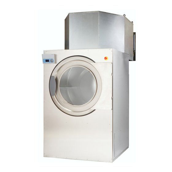
- Page 1 Installation manual Tumble dryer T4900CR, T41200CR Type N4... 438921081/EN Original instructions 2022.06.09...
-
Page 3: Table Of Contents
Symbols............................6 2 Warranty terms and exclusions......................7 3 Technical data.............................8 Drawing ............................8 Technical data ...........................9 3.2.1 T4900CR.........................9 3.2.2 T41200CR ........................11 4 Setup ...............................13 Unpacking ..........................14 4.1.1 Recycling instruction for packaging ..................14 4.1.2 Lowering the machine from the transport pallet ..............15 Siting ............................16... -
Page 5: Safety Precautions
Installation manual 1 Safety Precautions • Servicing shall be carried out only by authorized personnel. • Only authorized spare parts, accessories and consumables shall be used. • The machine is not to be used if industrial chemicals have been used for cleaning. •... -
Page 6: General Safety Information
– this will reduce, but not eliminate, the hazard. • Maximum mass of dry cloth: T4900CR: 50 kg, T41200CR: 67 kg. • A-weighted emission sound pressure level at working stations: < 70 dB(A). -
Page 7: Warranty Terms And Exclusions
Warranty will be applicable where the customer has used only genuine spare parts and has performed maintenance in accordance with Electrolux Professional user and maintenance documentation made available in paper or elec- tronic format. Electrolux Professional strongly recommends using Electrolux Professional approved cleaning, rinse and descaling agents to obtain optimal results and maintain product efficiency over time. -
Page 8: Technical Data
3 Technical data 3.1 Drawing fig.6806A Control panel Door opening, ⌀ 940 mm Electrical connection Steam connection Condensate connection Exhaust connection Delivery height Heating unit Air intake T4900CR 1290 2115 2690 1940 3290 T41200CR 1290 2305 2690 1940 3480 T4900CR... -
Page 9: Technical Data
Installation manual 3.2 Technical data 3.2.1 T4900CR 3.2.1.1 Steam heated machines Drum volume litres Weight net, Machine frame Weight net, Heating unit Weight net, Filter unit Drum diameter 1240 Drum depth Drum speed, medium load Rated capacity, filling factor 1:20 (Max. load) - Page 10 Installation manual 3.2.1.2 Electric heated machines Drum volume litres Weight net, Machine frame Weight net, Heating unit Weight net, Filter unit Drum diameter 1240 Drum depth Drum speed, medium load Rated capacity, filling factor 1:20 (Max. load) Rated capacity, filling factor 1:30 (Recommended load) Heating: Electric Air consumption, max.
-
Page 11: T41200Cr
Installation manual 3.2.2 T41200CR 3.2.2.1 Steam heated machines Drum volume litres 1200 Weight net, Machine frame Weight net, Heating unit Weight net, Filter unit Drum diameter 1240 Drum depth 1000 Drum speed, medium load Rated capacity, filling factor 1:20 (Max. load) Rated capacity, filling factor 1:30 (Recommended load) Heating: Steam at 700 kPa Air consumption, max. - Page 12 Installation manual 3.2.2.2 Electric heated machines Drum volume litres 1200 Weight net, Machine frame Weight net, Heating unit Weight net, Filter unit Drum diameter 1240 Drum depth 1000 Drum speed, medium load Rated capacity, filling factor 1:20 (Max. load) Rated capacity, filling factor 1:30 (Recommended load) Heating: Electric Air consumption, max.
-
Page 13: Setup
Installation manual 4 Setup Three packages are delivered containing the following units: Machine frame, filter unit and heating unit. Extra kit package for filter unit supplied in heating unit packing. fig.6767A Machine frame Filter unit Heating unit, steam Heating unit, electric... -
Page 14: Unpacking
Installation manual 4.1 Unpacking Remove each unit from the packaging. Remember to handle the units with care to avoid mechanical damage. 4.1.1 Recycling instruction for packaging fig.X02462 Fig. Description Code Type Wrapping film LDPE 4 Plastics Screw FE 40 Steel Packaging FOR 50 Wood... -
Page 15: Lowering The Machine From The Transport Pallet
Installation manual 4.1.2 Lowering the machine from the transport pallet • Remove the machine's three rear panels. • Remove the four screws holding the machine to the transport pallet: – 2 screws (A) in the machine's trailing edge (inside the machine). fig.6771A –... -
Page 16: Siting
Installation manual fig.6770 Note! The two front lower feet of the machine may have to be cut so as to avoid striking against the machine's baseplate. 4.2 Siting Place the machine on its final position. The figure shows minimum distance to a wall and / or other machines. fig.6794A Min. -
Page 17: Mechanical Installation
Installation manual 4.3 Mechanical installation Adjust the machine frame so that it stands level and steady on all four feet. Height adjustment shall be as low as pos- sible. The maximum height adjustment for the feet is 50 mm. This is only to be used with caution when the pallet lifter or the fork-lift truck is removed. -
Page 18: Filter Unit
Installation manual 4.4 Filter unit The filter unit is installed on the top of the machine frame. • Raise the filter unit over the top of the machine frame and lower the unit. Ensure that the gasket on the underside of the filter unit has not been damaged. - Page 19 Installation manual fig.6781 Note! The filters must be adjusted for a temperature of 200 ℃. • Remove the spring loaded filter holder. fig.6780...
-
Page 20: Heating Unit
Installation manual 4.5 Heating unit 4.5.1 Steam The steam unit is to be mounted on the filter unit as described below. • Insert two screws in the steam unit's two upper fixing holes. fig.6782 • Lift the unit into position and hang it using the keyhole like holes in the filter unit. fig.6784 •... - Page 21 Installation manual fig.6786A • Install the electrical cable plate. fig.6775 • Install the cover plate for the filter housing. fig.6777 • Install the temperature sensor for the filter housing. fig.6809...
-
Page 22: Electric
Installation manual 4.5.2 Electric The electric heating unit is installed on the filter unit as described below. • Insert two screws in the heating unit's two upper fixing holes. fig.6814 • Lift the unit into position and hang it using the keyhole like holes in the filter unit. fig.6815 •... - Page 23 Installation manual fig.6775 • Install the filter housing cover. fig.6777 • Install the temperature sensor for the filter housing. fig.6809...
-
Page 24: Transport Safety
Installation manual 4.6 Transport safety During transportation the transmission is locked. • Remove the transport safety device by cutting the ties (C) and removing the locking board (D). fig.6800A 4.7 Internal connections • Connect the filter chamber's temperature sensor. Pull and secure the cable with ties according to the illustration. fig.6787A •... -
Page 25: Steam-Heated Machine
Installation manual 4.7.1 Steam-heated machine • Install the filter chamber cover. fig.6793... -
Page 26: Electric Heated Machine
Installation manual 4.7.2 Electric heated machine • Connect the power cable (E) to the earth connection on the filter chamber. fig.7192A • Pass the red cable package (F) from the heating module through the filter unit's grommet, through the connection unit and on top of the connection terminal to the contactors (G). - Page 27 Installation manual fig.6839 • Connect the signal cables' connecting device to the connecting device at the right-hand edge of the connection unit. fig.6840 • Strap the power- and signal cables together in the filter unit. fig.7193 • Install the electric unit's two protective plates. Note! The outer rear plate of the filter unit must be loosened on the left-hand side.
- Page 28 Installation manual fig.6816A • Install the filter chamber cover. fig.6793...
-
Page 29: External Connections
Installation manual 4.8 External connections 4.8.1 Steam installation (only steam heated machines) The steam line must be connected to the upper side of the main steam line in order to prevent condensate running down to the tumble dryer. The branch line must be installed with a slope angle and must terminate higher than the inlet connection. It is important that the condensate line is installed lower than the outlet connection and maintains a slope angle all the way to the main condensate line. -
Page 30: Compressed Air Connection
Installation manual 4.8.3 Compressed air connection • Connect the pneumatic hose for steam valve (I) (steam-heated machine only). • Ensure that the two unused holes are properly plugged (J). • Connect compressed air to the machine (K). Steam heated machine Electric heated machine... -
Page 31: Evacuation
Installation manual 4.8.4 Evacuation • Connect evacuation pipe to the machine. For schematic diagram and guidelines for designing the evacuation system please refer to the section "Evacuation system". fig.6799 • Install the lower rear plate. fig.6798A • Install the cover plate over the motor control unit. -
Page 32: Electrical Installation
Installation manual 5 Electrical installation The electrical installation may only be carried out by qualified personnel. Machines with frequency-controlled motors can be incompatible with certain types of earth leakage circuit break- er. It is important to know that the machines are designed to provide a high level of personal safety, which is why items of external equipment such as earth leakage circuit breakers are not necessary but is recommended. -
Page 33: Electrical Connections
Installation manual 5.1 Electrical connections 5.1.1 T4900CR Heating alternative Main voltage Heating power Total power Recommended fuse Steam heated 200/230/240V 3 ~ 50/60 machines 400/415V 3 ~ 400/415/440/480V 3 ~ Electric heated 400/415V 3 ~ machines 400/415/440/480V 3 ~ * Total power and recommended fuse does not depend on the heating power in those cases. -
Page 34: Steam Heated Machine
Installation manual 5.2 Steam heated machine 5.2.1 Connection to mains voltage • Pull the mains cable through the grommet to the isolating switch. fig.6790 • Connect the mains cable. If there is a neutral conductor this must be connected to terminal N (A). Connect the earth (B). -
Page 35: Circuit Diagram
Installation manual • Install the rear upper plate. fig.6791 5.2.2 Circuit diagram The circuit diagram for the tumble dryer is located on the left-hand side of the control unit (C). fig.6790A... -
Page 36: Electric Heated Machine
Installation manual 5.3 Electric heated machine 5.3.1 Connection to mains voltage • Pull the mains cable through the grommet to the isolating switch. fig.6841 • Connect the mains cable. Connect the earth (B). fig.6842A • Hold the rear upper plate against the connection unit and connect the cooling fan. fig.6792 •... -
Page 37: Circuit Diagram
Installation manual fig.6791 5.3.2 Circuit diagram The circuit diagram for the tumble dryer is located on the left-hand side of the control unit (C). fig.6841A... -
Page 38: Evacuation System
5 x A fig.6810A The air consumption is: T4900CR: 2300 m T41200CR: 2500 m The resistance in the grating/slats on the air inlet cover plate should not exceed 10 Pa (0.1 mbar). Note! Gratings/slatted covers often block half of the total fresh air vent area. -
Page 39: Exhaust Duct
Installation manual 6.2 Exhaust duct • Only rigid or flexible metal duct should be used for exhausting. • Plastic ducting is not to be used. • Recommended material for exhaust is galvanized steel. • The duct is not to be assembled with screws of other fastening means that extend into the duct and catch lint. •... -
Page 40: Exhaust Dimensioning
Installation manual The exhaust duct diameter must not be reduced. 6.4 Exhaust dimensioning It is important that the machine has correct air volume compared to each machines power. If the air flow is smaller or larger this will result in a longer drying period. If the outlet pipe is long or the ventilation is not properly designed we recommend to clean the outlet pipes periodi- cally. -
Page 41: Function Check
Installation manual 7 Function check May only be carried out by qualified personnel. A function check must be made when the installation is finished and before the machine can be ready to be used. Whenever a repair has been made, a function check must be performed before the machine can be used again. Inspection of the door's solenoid switch Start the machine. -
Page 42: Disposal Information
Installation manual 8 Disposal information 8.1 Disposal of appliance at end of life Before disposing of the machine, make sure to carefully check its physical condition, and in particular any parts of the structure that can give or break during scrapping. The machine’s parts must be disposed of in a differentiated way, according to their different characteristics (e.g. - Page 44 Electrolux Professional AB 341 80 Ljungby, Sweden www.electroluxprofessional.com...