Table of Contents
Advertisement
Quick Links
Advertisement
Table of Contents

Related Manuals for Planet IECJ-300

Summary of Contents for Planet IECJ-300
- Page 1 Industrial 3-Port EtherCAT Junction Slave IECJ-300 User's Manual...
-
Page 2: Table Of Contents
Table of Contents 1. Package Contents ................. 3 2. Product Features .................. 4 3. Product Specifications ................5 4. Hardware Introduction ................6 4.1 Three-View Diagram............... 6 4.2 Wiring the Power Inputs ..............8 4.3 Grounding the Device ..............9 5. Installation ..................10 5.1 DIN-rail Mounting Installation ............ -
Page 3: Package Contents
1. Package Contents Thank you for purchasing PLANET Industrial EtherCAT Junction Slave. In the following sections, the term “Industrial EtherCAT Junction Slave” means the IECJ-300. Open the box of Industrial EtherCAT Junction Slave and carefully unpack it. The box should contain the following items: IECJ-300 x 1 QR Code Sheet x 1... -
Page 4: Product Features
2. Product Features z Three 100BASE-TX RJ45 bus interfaces z LED indicators for the input status z Dual 9 ~ 48V DC wide input voltage range z Supports EtherCAT distributed clock (DC) mode z EtherCAT conformance test tool verified... -
Page 5: Product Specifications
3. Product Specifications Model IECJ-300 Communication Interface Port 3 x 100BASE-TX RJ45 Distance between max. 100 m (100BASE-TX) Stations Copper Data Transfer Shielded Ethernet/EtherCAT cable (min. cat5) Medium EtherCAT Protocol EtherCAT Power Input Voltage Range Dual 9~48V DC Power Consumption Maximum 1.44W Mechanical Dimensions (W x D x H) 33 x 70 x 104mm Installation DIN-rail mounting and wall mounting Case Material IP30 metal... -
Page 6: Hardware Introduction
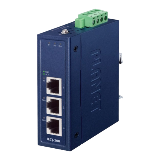
The LED indicators are also located on the front panel. 147.00 40.00 40.00 48.80 18.00 28.00 18.00 91.00 9.00 18.00 52.00 52.00 21.69 28.65 70.00 104.00 30.00 DC Input: PWR1 PWR2 9-48V , 0.6A max. 30.00 50.00 Figure 1: IECJ-300 Three-View Diagram... - Page 7 Front View IECJ-300 Figure 2: IECJ-300 Front View LED Definition: System Color Function Green Lights to indicate power 1 has power. Green Lights to indicate power 2 has power. Light The device is in the state of operation. The device is in the state of operation Single Flash without risk.
-
Page 8: Wiring The Power Inputs
1. Insert positive and negative DC power wires into contacts 1 and 2 or contacts 3 and 4 for POWER. 1 2 3 4 DC Input: PWR1 PWR2 9-48V , 0.6A max. Figure 3: IECJ-300 Top View 2. Tighten the wire-clamp screws for preventing the wires from loosening. Power1 Power2 V1+ V1- V2+ V2-... -
Page 9: Grounding The Device
1. The DC power input range is 9-48V DC. 2. The device provides input voltage polarity protection. PWR1 and PWR2 must provide exactly the same DV voltage for power load balance while operating with dual power input. 4.3 Grounding the Device Users MUST complete grounding wired with the device; otherwise, a sudden lightning could cause fatal damage to the device. -
Page 10: Installation
5. Installation This section guides you to installing the Industrial EtherCAT Junction Slave on the DIN rail and wall. Please read this chapter completely before continuing. This following pictures show the user how to install the device, and the device is not IECJ-300. 5.1 DIN-rail Mounting Installation... -
Page 11: Wall-Mount Plate Mounting
5.2 Wall-mount Plate Mounting 5.3 Side Wall-mount Plate Mounting You must use the screws supplied with the wall-mounting brackets. Damage caused to the parts by using incorrect screws would invalidate your warranty. -
Page 12: Getting Started
This chapter provides a basic overview of how to configure and operate your IECJ series. 6.1 Connecting the Power and the Host PC Step 1: Connect both the Port 1 of the IECJ-300 and RJ45 Ethernet port of Host PC. Ensure that the network settings on the Host PC have been correctly configured and are functioning normally. Ensure that the Windows... - Page 13 Step 3: Verify the “P1” LED indicator on the IECJ-300 module is Green; “Port 1” LED indicator is Green. TP IN SFP OUT LNK/ 100BASE-FX IECJ-300 IECC-210T...
-
Page 14: Configuration And Operation
Inserting into the EtherCAT network Installation of the latest XML device description (ESI). Make sure to use the latest installation description to install the latest XML device. This can be downloaded from PLANET website (https://www.planet.com.tw/en/support/downloads?&m ethod=keyword&keyword=IECJ-300) and check the online FAQs for the installation of the XML device. - Page 15 Acknowledge all dialogs with “OK”, so that the configuration is in the “FreeRun” mode. Step 2: Configuration via TwinCAT In the left-hand window of the TwinCAT System Manager, click on the brand of the EtherCAT Box you wish to configure (Take the IECJ-300 for an example). Click Box 1 to get and configure state.
-
Page 16: Customer Support
Customer Support Thank you for purchasing PLANET products. You can browse our online FAQ resource on PLANET web site first to check if it could solve your issue. If you need more support information, please contact PLANET switch support team. - Page 17 FCC Warning This device has been tested and found to comply with the limits for a Class A digital device, pursuant to Part 15 of the FCC Rules. These limits are designed to provide reasonable protection against harmful interference when the equipment is operated in a commercial environment. This equipment generates, uses, and can radiate radio frequency energy and, if not installed and used in accordance with the Instruction manual, may cause harmful...