Table of Contents
Advertisement
Quick Links
Advertisement
Table of Contents

Related Manuals for Multitech MT2834MR


Summary of Contents for Multitech MT2834MR
- Page 1 PN 88300150 MT2834MR, MT2834MRI, and MT2834MRK Owner’s Manual 4/3/01...
- Page 2 Furthermore, Multi-Tech Systems, Inc. reserves the right to revise this publication and to make changes from time to time in the content hereof without obligation of Multi-Tech Systems, Inc. to notify any person or organization of such revisions or changes.
-
Page 3: Table Of Contents
PN 88300150 CHAPTER 1 - INTRODUCTION AND DESCRIPTION 1.1 Introduction ...6 1.2 How To Use This Manual ...6 1.3 Description ...7 1.4 FCC Regulations for Telephone Line Interconnection...8 1.5 Canadian Limitations Notice ...10 1.6 Compliance with BABT Requirements (MT2834MRK only) ...11 1.7 Technical Specifications ...11 1.8 Power...13 1.9 Modem LED Indicators ...13... - Page 4 Appendix G - V.25bis Operation ...85 Appendix H - RS232C Interface Specifications ...93 Appendix I - Cable and Connector Diagrams...96 Appendix J - Escape Methods Used by Multi-Tech Systems ...100 Appendix K - Remote Configuration ...103 Appendix L - MT2834MRI PC Board ...104...
-
Page 5: Chapter 1 - Introduction And Description
MT2834MR, from Multi-Tech Systems. This owner’s manual will help you install, configure, test, and use your modem. Your MT2834MR is designed to operate in two modes. First, it functions as a 33,600 bps leased line modem with dialback security. Communications over leased lines have been popular for many years primarily over 4-wire lines using V.29 modulation techniques. -
Page 6: Description
This chapter provides information on loopback testing for your MT2834MR. Chapter 7 - DIP Switches and Jumpers The MT2834MR’s printed circuit board options are covered in this chapter. The DIP switch settings and on-board jumper plugs are explained in detail, including all default settings. -
Page 7: Fcc Regulations For Telephone Line Interconnection
PN 88300150 FCC Regulations for Telephone Line Interconnection 1. No repairs are to be made by you. Repairs are to be made only by Multi-Tech Systems or its licensees. Unauthorized repairs void registration and warranty. Contact Multi-Tech Systems, Inc. for details of how to have repairs made. -
Page 8: Compliance With Babt Requirements (Mt2834Mrk Only)
PN 88300150 Repairs to certified equipment should be made by an authorized Canadian maintenance facility designated by the supplier. Any repairs or alterations made by the user to this equipment; or equipment malfunctions, may give the telecommunications company cause to request the user to disconnect the equipment. - Page 9 There is no guarantee of correct working in all circumstances. Any difficulties should be referred to Multi-Tech. c. If sockets are required for connection to the PBX, use the BT post card only if BT owns the wiring to the PBX.
-
Page 10: Technical Specifications
Technical Specifications Tradename MultiModemV34 Model Number MT2834MR, MT2834MRK, MT2834MRI Data Rates (bps) Three independent modems (Modem A, B, C) each operating at 33,600, 31,200, 28,800, 26,400, 24,000, 21,600, 19,200, 16,800, 14,400, 12,000, 9600, 4800, 2400, 1200, or 0-300 bps... - Page 11 PN 88300150 Automatic Dialing Choice of “Standard AT” command asynchronous dialing, “AT” command- controlled asynch-to-synch DTR dialing, or ITU-T V.25bis Synchronous or Asynchronous dialing. Automatic Leased When in dial back-up mode, modem will Line Restoral attempt leased line restoral periodically according to software configuration. Modulation Trellis Coded Modulation (TCM) at 33,600, 31,200, 28,800, 26,400, 24,000, 21,600, 19,200, 16,800, 14,400, 12,000, and 9600 bps;...
-
Page 12: Power
PN 88300150 Transmit Level -10 dBm (dial-up) 0 dBm (leased line, MT2834MR) -13 dBm (private wire MT2834MRK) -11dBm (MT2834MRI) Note: The Transmit Values apply to the domestic, U.K., and the standard International defaults only, country-specific modems may vary. Frequency Stability +0.01%... -
Page 13: Modem Led Indicators
1.10 BUSY Switch The MT2834MR contains three two-position BUSY switches on the front panel. Each switch can be used to create a “busy out” (OOS) condition for one of the three on-board modems (i.e., Modem A, B, or C). -
Page 14: 1.11 Controls On Pc Board
Switches control various modem options or set default values for Command mode operation. There are also “jumper” option settings on the circuit board, which control V.54/Test (OOS) functions. The toggle switch positions on the MT2834MR are be labeled “Busy” for each of the three on-board modems (Modems A,B,C). -
Page 15: Introduction
Manual Dial Backup Call Termination If your MT2834MR is in the leased line mode (DIP Switch #10 in the Down (“Closed”) position) and with a dial back-up operation in process, there are two ways to manually terminate (other than automatic leased line restoral) the dialback call. -
Page 16: Dial-Up Automatic Answering
With your MT2834MR in the dial-up mode (12-Position DIP Switch #10 in the UP position), the MT2834MR can be used as an automatic answering modem. The MT2834MR, when in its idle state, will be set up with originate mode frequencies. An incoming ring signal will automatically switch the modem into answer mode. - Page 17 PN 88300150 2. DTR Control. If DTR (Data Terminal Ready) is turned off for 50 milliseconds or more, a disconnect will occur. This is probably the most common method used by computer systems at the automatic answer end of the line to cause the answering modem to disconnect after log off procedures. 3.
-
Page 18: Introduction
It is important to point out the difference between the letter O and the number 0. Both of these characters will be used in the MT2834MR’s commands. As you can see, the letter O is “fatter” than the number 0. -
Page 19: At Commands
PN 88300150 AT Commands A variety of autodial operations and modem options are controlled when the MT2834MR is in Command Mode. This chapter covers each command in detail. There are also several option configurations stored in “S-Registers”, which can also be accessed in Command Mode (refer to Chapter 6). Error Correction commands are covered in Chapter 5 of this manual. -
Page 20: Result Codes
PN 88300150 $MBn Modem Baud Rate Dial Stored Telephone Number NdNe Number Linking On-line from Command Mode Pulse Dial &Pn Set Pulse dial ratio* Parity Select Result Codes &Qn Command set select Reverse this mode &Rn CTS control Ring message on callback modem &RFn CTS follow RTS control Retransmit count... -
Page 21: Result Codes
You can choose result codes that closely match those of the “Standard AT” command set (“Standard AT” Responses) or enhanced function result codes that have been used in Multi-Tech modems in the past (“Multi-Tech responses”). The &Q command selects which result codes will be used. -
Page 22: Command Mode Fundamentals
It is not necessary to hit ENTER to execute this command. Many MT2834MR commands consist of a letter, followed by a number (0, 1, etc.). If a command like this is typed without the number, the modem will assume that its value is zero (0). For example, if you type ATH as a command without a 0 or 1 following the H, the command will be ATH0. -
Page 23: Dialing Commands
Hanging Up, and Bringing the Phone Line Off Hook You can make the MT2834MR hang up (go On Hook), or go Off Hook, with the H command. Type ATH1 to bring the line Off Hook, just as if you had picked up the telephone handset. -
Page 24: Dial Modifiers
P, T Pulse or Tone Dialing The MT2834MR can dial numbers using either pulse or tone dialing, or a combination of both methods. Pulse dialing is the method used by rotary-dial telephones, which involves the timed opening and closing of a line relay. Tone dialing is that used by pushbutton Touch- Tone™... -
Page 25: Phone Number Memory Commands
1212) and wait for the time specified in S-Register S7 for at least one ringback and 5 seconds of silence. If a busy signal is detected, the MT2834MR hangs up and generates a BUSY result code. If it does not detect 5 seconds of silence, a NO ANSWER result code is generated after hanging up. - Page 26 Number Linking You may cause the MT2834MR to dial a second number automatically if the first number you dialed is busy. This is useful in a situation where a computer can be accessed through more than one phone number. This is called “linking”.
-
Page 27: Immediate Action Commands
+++AT<CR> Escape Sequences -- Entering Command Mode While Still On-Line It is possible to cause the MT2834MR to enter the Command mode after the modem has gone on-line with a remote modem, without disconnecting the call. This is accomplished by typing an Escape Code. - Page 28 (Originate or Answer) that it was in prior to going into Command mode. Forcing Answer Mode With the A command you can force the MT2834MR into the Answer mode. Type ATA Mode when in Command mode to immediately bring your modem off-hook, out of Command mode and into the On-Line Answer mode, and cause it to transmit its carrier signal over the phone line.
-
Page 29: Configuration Commands
ROM and from the DIP-Switch settings. Modem Reset Type the Z command to reset all MT2834MR configurations to their factory default settings, and to clear the Command mode buffer. When you type ATZ, the result is the same as if you had disconnected, and then reconnected power to the modem. - Page 30 NO CARRIER, or as the digit 3. Type ATV0 (or ATV) to cause the MT2834MR to display the Result Codes as digits. Type ATV1 to display the Result Codes as words. If you do not select a method, the factory default setting will cause the modem to use verbose results.
- Page 31 This capability (“smart dialing”) allows the modem to wait for a dial tone, and when one is detected, to begin dialing immediately. The MT2834MR also can detect a distant busy signal if after dialing, it reaches a busy number. This is useful because it allows the modem to immediately abandon a call, rather than wait 45 seconds for a carrier signal that will never come.
-
Page 32: Rs232 Interface Commands
&D Data Terminal Ready Control Data Terminal Ready (DTR) on pin 20 of the RS232C interface is required for the MT2834MR to operate. A high DTR signal tells the modem that the device to which it is connected is active, or “ready” to communicate through the modem. If the signal is not being provided on the RS232C interface, 12-position DIP-Switch #1 can be used to force the DTR signal on. -
Page 33: Phone Line Conditioning Commands
2400 bps ITU-T V.22 bis (Bell 2400) standard modem, a ITU-T V.22/Bell 212A (1200 bps) modem or a Bell 103/113 (300 bps) modem. The function of the #A command is to detect and select the operational baud rates which the MT2834MR will use for initial handshake and speed selection. - Page 34 The modem continually monitors the connection and adjusts itself, automatically and incrementally, to the optimal line speed. AT#F0 (or AT#F) will cause no fallback when on-line. AT#F1 will cause the MT2834MR to fall back (based on the error rate or if three retrains have occurred within a two minute period) from 28,800 to 26,400 to 24,000 to 21,600 to 19,200 to 16,800 to 14,400 to 12,000 to 9600 to 4800 to 2400 bps.
-
Page 35: Miscellaneous Commands
Enable or Disable Recognition of Remote Digital Loop Signal The MT2834MR has several test features, which are covered in detail in Chapter 6. The tests are activated with different U commands, such as ATU0, ATU1 and so forth. There is one command, however, that is really a configuration command, so we will cover it here. - Page 36 &M Synchronous/Asynchronous Mode Switching The &M command is used to set the on-line mode of the MT2834MR to either Synchronous or Asynchronous. AT&M0 sets the mode to Asynchronous, and all communications will be Asynchronous, both in On-line and Command mode. AT&M1 causes the MT2834MR to communicate asynchronously when in Command mode, and to switch to synchronous mode while on-line.
- Page 37 AT command, *C1. Turns off Caller ID detection. Turns on Caller ID detection for the MultiCommManager. Is storable in MT2834MR memory and turns on Caller ID reporting on the serial port by the MultiCommManager. Lets you see the last Caller ID’s number.
- Page 38 PN 88300150 With the *R1 command, the modem will put out a ring message and raise pin 22 on the RS232. No ring message on outbound callback attempt. Ring message and pin 22 enabled on outbound callback attempt. The factory default setting is *R0. User Control of V.32terbo in Answer Mode V.32terbo enabled.
-
Page 39: Introduction
PN 88300150 Introduction This chapter covers MT2834MR software registers called S-Registers, where certain MT2834MR modem and Command mode configurations are stored. Each S-Register is assigned a number (S0, S1, S2, etc.). Use the S command to read and/or change the value stored in an S-Register (ATSr? to read and ATSr= to change S-Register values). - Page 40 PN 88300150 Line Feed Character Unit: ASCII Range: 0-127 Default: 10 Description: S4 defines the character recognized as Line Feed. The default setting is CTRL-J (Decimal 10), which is the ASCII code for the Line Feed key on most keyboards. S4 may be set for any ASCII character.
- Page 41 PN 88300150 Carrier Detect Response Time Unit: 100 mSec. Range: 1-255 Default: 6 Description: S9 sets the time delay between when the modem first detects a valid incoming carrier signal and when the modem turns on its Carrier Detect circuit. The default setting is 600 milliseconds, or six units of 100 mSec each (Decimal 6).
- Page 42 Range: 10-255 min. Default: 30 min. Description: When the MT2834MR is in the dial back-up mode of operation, it will periodically check the leased line to see if it’s operational and try to restore the leased line if possible. The frequency of restoral attempts is defined by the contents of S-Register S18.
- Page 43 PN 88300150 Inactivity Timer Unit: 1 min. Range: 0-255 Default: 0 Description: S30 causes the modem to disconnect if no data is transmitted or received for a specified time. This timer runs during both Reliable and Normal connections. The timer restarts any time a data character is passed through the serial port (either sent or received).
-
Page 44: Reading And Assigning S-Register Values
2. In a second example, let’s say that you wish to configure the MT2834MR modem to answer incoming calls after the 30th ring instead of after the first ring. To configure S-Register S0 with a value of 30, type ATS0=30 and hit ENTER. -
Page 45: Summary
Auto-Reliable mode (&E1) lets the modem automatically turn V.42 on when it detects its use in another modem. Flow control methods are used by the MT2834MR to prevent data loss from buffer overflow. The modem both initiates flow control and responds to pacing, using either Xon/Xoff commands or RS232C/V.24 signaling via CTS (from the modem) or RTS (from the computer/terminal). -
Page 46: Introduction
PN 88300150 Introduction Your MT2834MR has intelligent features beyond those of the AT command set (described in Chapter 3 of this manual). This chapter covers these high performance features and commands which provide error correction, data compression and speed conversion capabilities. Error correction in your modem is via the ITU-T V.42 standard. -
Page 47: Data Compression
MNP class 5 is a proprietary technique for data compression that provides a data compression capability of two-to-one. The MT2834MR must be in error correction mode before it can compress data (LAP-M error correction for V.42bis data compression or MNP error correction for MNP 5 data compression). By using the #L command, you can select which error correction to use. -
Page 48: Mode Select Command (#L)
#L3 in effect. Modes of Operation You can configure your MT2834MR in one of three different V.42 modes of operation (each mode can be with or without compression). These are the Normal, Reliable and Auto-Reliable modes. The modes and data compression features are selected with commands covered in Section 5.13. -
Page 49: Introduction To Flow Control
Normal mode. This V.42 handshaking procedure generally takes about five seconds. When operating in V.42 Reliable mode, the MT2834MR uses its memory, or buffer, to store data as it is received. During periods of error-caused retranmissions or compression slowdowns, this buffer may fill up. -
Page 50: Terminal/Computer-Initiated Pacing (&E13)
When the modem is set for Pacing Off, it will ignore pacing. In order for the MT2834MR to be set for Pacing On, a modem-initiated method of flow control must be previously selected. Once this is done, the MT2834MR will respond to either Xon/Xoff commands, or to the toggling of the RTS (Request to Send) signal on Pin 4 of the RS232C interface, depending on what you selected earlier as your Modem-Initiated Flow Control method. -
Page 51: Normal Mode Modem Flow Control (&E10 And &E11)
5.11 Normal Mode Modem Flow Control (&E10 and &E11) When two MT2834MR’s are connected in Normal mode (not using error correction), Xon/Xoff can be used to control the flow of data between the modems. Flow control can be turned on or off with the Normal Mode Modem Flow Control commands. -
Page 52: 5.14 Error Correction Result Codes
(&E15) unless &E1 (auto-reliable mode) or &E2 (reliable mode) is also selected. 5.14 Error Correction Result Codes When the MT2834MR is operating with error-correction enabled, five of its responses are altered, to let you know that you have made a connection in Reliable mode. These Result Codes for a V.42 MNP... -
Page 53: 5.15 Speed Conversion
Speed conversion allows the MT2834MR to communicate at one speed over the phone line, and at another speed at the RS232C interface. The speed (also referred to here as “bps,” or “baud rate”) can be fixed at the RS232C interface independently of the baud rate of the on-line transmissions. - Page 54 However, if the MT2834MR originates a call to another modem that is unable to connect at the baud rate of the MT2834MR, the MT2834MR will automatically drop to a lower baud rate in an attempt to match the speed of that modem.
-
Page 55: 5.16 Related Commands
PN 88300150 command speed, although the baud rate value stored by the $SB command will remain the same. This provides you with a convenient way to switch the serial port speed, while still making it easy to go back to the original speed automatically the next time the modem is powered up or reset with an ATZ command. -
Page 56: Summary
The factory default setting is $R0. V.42 Error Correction at 300 bps At 300 bps, error correction is not normally used. $E1 lets the MT2834MR to function in either Normal (&E0), Auto-Reliable (&E1) or Reliable (&E2) mode. $E0, which is the factory default setting, disables V.42 error correction altogether. - Page 57 V.42 on when it detects its use in another modem. Flow control methods are used by the MT2834MR to prevent data loss from buffer overflow. The modem can both initiate it (“flow control”) and respond to it (“pacing”), using either Xon/Xoff commands or RS232C signaling via CTS (from the modem) or RTS (from the computer or terminal).
-
Page 58: Introduction
PN 88300150 Introduction Each time you power up the MT2834MR, it performs an automatic self- test to ensure proper operation. The MT2834MR also has four diagnostic test features: Local Analog Loopback, Digital Loopback (remote/automatic), Digital Loopback (local/manual) and a modem Back-to-Back test. -
Page 59: Local Analog Loopback Test/V.54 Loop 3
PN 88300150 Local Analog Loopback Test/V.54 Loop 3 In this test, data from your computer or terminal is sent to your modem’s transmitter, converted into analog form, looped back to the receiver, converted into digital form and then received back at your monitor for verification. -
Page 60: Digital Loopback Test/V.54 Loop 2 (Local/Manual)
In this test, your modem must be On-Line with another modem that can respond to a request for Digital Loopback, such as another MT2834MR. The Digital Loopback Test is an on-line test that loops data sent from one modem across the phone line to another modem, then back to the first modem. See Figure 6-2. -
Page 61: Digital Loopback Test/V.54 Loop 2 (Remote/Automatic)
In this test, your modem must be On-line with another modem set up to respond to a request for Digital Loopback, such as another MT2834MR. With the MT2834MR, this ability to respond is controlled by the &T command. AT&T4 enables the response to Digital Loopback Test (remote/automatic). AT&T5 disables the response. -
Page 62: Back-To-Back Test
This test lets you connect two MT2834MRs with an RJ11 cable to verify proper operation. Using a MT2834MR that is known to be operational, you can test a second MT2834MR that is suspect. 1. Plug the modular ends of an RJ11 cable into both MT2834MR’s LINE jack connectors. -
Page 63: Synchronous Mode Testing
Local Analog Loopback Test, documented in section 6.7. Local Analog Loopback Test (Sync. Mode) This test diagnoses the connection between your MT2834MR and your computer or terminal. In Local Analog Loopback Test mode, data entered at the local computer or terminal are sent through the local modem’s transmit and receive circuits (much like entering an ATU or ATU1 command in Asynchronous... -
Page 64: Digital Loopback Test (Local/Manual) (Sync. Mode)
PN 88300150 Digital Loopback Test (Local/Manual) (Synchronous Mode) This test must be run when you have a data connection with another modem. If a Local Analog Loopback Test resulted in errors, and this test passes without errors, then the problem exists in your computer-to- modem connection. -
Page 65: Introduction
PN 88300150 Introduction There are 3 sets of DIP-Switches and 3 two-position jumpers on the MT2834MR card. To remove the MT2834MR modem card from the CC4800 rack, pull the ejector levers away from the rack (if necessary loosen the retaining screw first), then carefully slide the modem card out of the rack. -
Page 66: 16-Position Dip-Switches
(Asynchronous/Synchronous Mode/Leased Line/Dial-Up) The MT2834MR must have a high DTR signal in order to operate. This signal is provided to each modem by the terminal or computer to which it is attached, through the RS232/V.24 interface on pin 20. If your terminal is not providing DTR to the modem, you can force the DTR signal DIP-Switch #1. - Page 67 (Asynchronous/Synchronous Mode/Leased Line) The MT2834MR can adjust to dB transmission levels required by some phone carriers. With DIP-Switch #3 in the DOWN position, the MT2834MR transmits at 0 db. With DIP-Switch #3 in the UP position, transmission is at -15dB.
- Page 68 The MT2834MR can be used with UNIX equipment which employs ACK flow control to monitor data integrity. The MT2834MR can do UUCP “spoofing”, where the modem is able to generate ACKs at the DTE interface. Data is then transmitted more time-efficiently, because the delay of waiting for data to be received then for the ACK to be returned at the remote end is eliminated.
- Page 69 PN 88300150 Switch #6 Maximum Throughput Setting (Asynchronous Mode/Leased Line/Dial-Up) In some applications, you may want to dial into services with maximum throughput on. Other applications require maximum throughput off (e.g., service not supporting error correction, or the V.42 handshake interferes with logon sequence).
- Page 70 Internal/External Clocking (Synchronous Mode/Leased Line/Dial-Up) With the MT2834MR in Synchronous Mode, the transmit clock can be supplied by the DTE on pin 24 of the RS232C/V.24 interface by DIP-Switch #11 positioned UP. DIP-Switch #11 in the DOWN position enables the DCE to control clocking.
-
Page 71: Jumper Settings
(Factory Default Setting = DOWN) Jumper Settings The MT2834MR has three two-position jumpers (one for each modem) for OOS and service. Each set of OOS jumpers defines pin 25 of the RS232C/D interface as an input (OOS) or an output (Test Mode) for one of the three modems. - Page 72 C as input (OOS) for the option, and output (Test Mode) as the default setting. The location of these jumpers can be seen in Figure 7-1 on the right-hand side of the board. Pin 25 Output (OOS) (MT2834MR Default) (MT2834MRI Default) 4/3/01...
-
Page 73: Introduction
WILL ITS LIABILITY EXCEED THE PURCHASE PRICE FOR DEFECTIVE PRODUCTS. Tech Support Multi-Tech has an excellent staff of technical support personnel available to help you get the most out of your Multi-Tech product. If you have any questions about the operation of this unit, call (800) 972-2439 (U.S.A. -
Page 74: Service
4. Highlight ’Configure’ option in the MAIN MENU and press ENTER. Highlight ’Active Port’ and select the COM port to which you have your MT2834MR attached. Highlight ’Baud Rate’ and select the rate you want to program at. Press ESC when finished. - Page 75 PN 88300150 ASCII/Hex/Decimal Conversion Chart CTRL CODE HEX DEC CODE HEX DEC CODE HEX DEC CODE HEX DEC “ & ‘ < > — Null, or all zeros Start of Heading Start of Text End of Text End of Transmission Acknowledge Bell or Alarm Backspace...
- Page 76 PN 88300150 Dial Pulse and Tone-Dial Frequencies Closed Open Digit 2 In the example above, the digit 2 is pulse dialed, followed by the digit 1. Each pulse consists of an A mSec. open and a B mSec. closed, where A will be either 60 or 67 mSec and B will be either 40 or 33 mSec., for a total of 100 mSec.
-
Page 77: Appendix Cdip-Switch Summary
Disable Command Mode *Down Enable Command Mode No function *Down Dial-Up Operation Down Leased Line Operation "AT" Responses *Down Multi-Tech Responses Synchronous Mode *Down Asynchronous Mode See page C-3 for information on DIP-Switches #13 - #16 4/3/01 Appendix C DIP-Switch Summary Effect... - Page 78 PN 88300150 DIP-Switch Condition Synchronous Mode DTR Dependent On interface Down DTR forced On at all times SDLC Mode On Down BSC Mode On Disable Command Mode Response (dial up) *Down Enable Command Mode Response (dial up) -15 dB Transmission (leased line) *Down 0 dB Transmission (leased line) Note: dB transmission levels on International models may be different from those values shown above.
-
Page 79: Appendix D Result Code Summary
Modem has detected carrier at 26400 bps and gone on-line. CONNECT 28800 Modem has detected carrier at 28800 bps and gone on-line. Note: If the MT2834MR is used in MNP Reliable mode, the following Result Codes change: CONNECT RELIABLE CONNECT 1200 RELIABLE... - Page 80 CONNECT 26400 LAPM CONNECT 28800 LAPM Note 1: If the MT2834MR is used with data compression, the word COMPRESSED or the letter C is added to the result codes. Note 2: If Standard AT Command Set 2400 Result Codes are selected with &Q command, the following...
-
Page 81: Appendix E S-Register Summary
PN 88300150 * indicates Values for MT2834MRK units only. REGISTER UNIT RANGE DEFAULT DESCRIPTION 1 ring 0-255 1 ring 0-255 ASCII 0-127 ASCII 0-127 ASCII 0-127 ASCII 0-32 S6 1 second 2-255 S7 1 second 1-255 1 second 0-255 100 mSec 1-255 100 mSec 1-255 1 mSec 1-255... -
Page 82: Appendix F - At Command Summary
*** *C0 turns off Caller ID detection. *C1 turns on Caller ID detection for the MMM. *C2 is storable in MT2834MR memory and turns on Caller ID reporting on the serial port by the MMM. *C3 lets you view the last Caller ID’s number. - Page 83 PN 88300150 n = 0 or 1 *** $E0 disables 300 baud error correction. $E1 enables 300 baud error correction. &En n = 0 thru 15 &E0 means V.42 Normal Mode. *** &E1 means V.42 Auto-reliable Mode. &E2 means V.42 Reliable Mode. &E3 means no modem-initiated flow control.
- Page 84 Q1 means Result Codes will be suppressed (quiet). Q2 means Dumb Answer Mode. &Qn n = 0 or 1 *** &Q0 selects Multi-Tech command set. &Q1 selects AT command set. n = 0 or 1 *** R0 means modem will not reverse modes.
- Page 85 PN 88300150 &SF1 selects DSR independent. $SPn n = 0 or 1 *** $SP0 disables UUCP Spoofing $SP1 enables UUCP Spoofing Modem will tone-dial numbers following the T. &Tn n = 4 or 5 &T4 means Enable Response to Request for Remote Digital Loopback.
-
Page 86: Appendix G V.25Bis Operation
PN 88300150 Appendix G V.25bis Operation Operation of your modem in ITU-T V.25bis mode provides you with an alternate set of commands and responses to those described in the AT Command Mode chapter of this manual. The V.25bis mode performs dialing functions in the asynchronous or synchronous mode according to the recommendations of the ITU-T (Consultative Committee of International Telephony and Telegraphy). - Page 87 PN 88300150 Another asynchronous mode issue is connecting at a different speed than the speed at which the serial port is set. If your modem port speed is different from the serial port speed, you must either: 1. Enable speed conversion and have flow control on, or 2.
- Page 88 PN 88300150 V.25bis Mode AT Commands The following commands either alter standard V.25bis behavior (so you must be careful in their use) or they are not allowed, as indicated. All other commands can be used in V.25bis operation. Not Allowed Not Allowed Not Allowed Not Allowed...
- Page 89 PN 88300150 LSDmm;dd...dd Phone number on the Delay list LSFmm;dd...dd Phone number on the forbidden list CON ssss Connection at ssss speed (if X1 in effect) V.25bis AT Commands The AT commands associated with V.25bis mode are described as follows. Note that one command enables and disables V.25bis mode and the rest are only operable in the V.25bis mode.
- Page 90 PN 88300150 Dial Phone Number Stored in Memory (CRS) Command A telephone number that you have stored in the modem’s memory may be automatically dialed after checking it against the Delayed and Forbidden number lists by entering CRSmm where mm = 01, 02, 03, 04,...20.
- Page 91 Due to the flexibility of the V.25bis standard, each country may establish specific regulations governing the way operations are handled. The purpose of this document is to detail each country’s specific regulations that affect operation of V.25bis in Multi-Tech modems. 1. Italy a) Command/Indication modifications 1.
- Page 92 PN 88300150 2. Switzerland a) Command/Indication modification 1. Modem must remain on-hook for 5 seconds after disconnect 2. Modem must remain on-hook for 5 minutes after consecutive failed calls 3. If modem must remain on-hook, then it is “paused” 4. If the modem is paused and a call is attempted a PAU indication is given. a) PAUt Modem is paused for t minutes b) Delayed and Forbidden list behavior 1.
- Page 93 PN 88300150 5. Belgium a) Command/Indication modification (none) b) Delay and Forbidden list behavior 1. 1 min. delay between calls 2. After 4 retries, the number is put on the forbidden list 3. The number remains on the forbidden list for 1 hour after entry to forbidden list 4.
-
Page 94: Appendix Hrs232C Interface Specifications
The input impedances of all modem circuits which accept signals from the data processing terminal or CPU equipment have DC resistances of 4.7K. For more specific details, consult the EIA RS232C standard itself. The following chart lists the EIA RS232C interface pins and circuits present on the MT2834MR’s RS232C Interface connector. All other pins are unused. - Page 95 Signals on this circuit are generated by the customer’s terminal and transferred to the transmitter of the MT2834MR. A positive signal is a space (binary 0) and a negative signal is a mark (binary 0). The transmitting terminal should hold this line in the marking state when no data is being transmitted, including intervals between characters or words.
- Page 96 PN 88300150 The TC signal is provided only when the MT2834MR is used in the synchronous mode. The clock is a square wave and is used to provide the computer or terminal with timing information for its Transmit Data circuit (pin 2). This clock is provided on the interface at all times when the modem is in synchronous mode.
- Page 97 PN 88300150 Cable and Connector Pin Diagrams Frame Ground Transmit Data Receive Data Request to Send Clear to Send Data Set Ready Signal Ground Carrier Detect + Voltage Test High Speed Transmit Clock Receive Clock Data Terminal Ready Ring Indicator Terminal Busy 25-pin Male Connector (DB25P type) 25-pin Female Connector (DB25S type) (on back of modem or CC216 rack)
- Page 98 PN 88300150 MULTI-TECH SYSTEMS’ ESCAPE METHODS Introduction You may find it necessary sometimes to issue AT commands to your modem while you are on-line with a remote modem, without disconnecting the call. If so, you will want to take advantage of Escape methods which allow you to change the modem’s mode of operation from On-Line mode to Command mode,...
- Page 99 PN 88300150 Escape Method 1: +++AT<CR> In the following example, a user who is On-Line decides to set S0 Register to 1, to configure the modem to answer on the first ring. The user enters the sequence +++AT<CR> . The sequence is sent to the modem. The modem transmits the +++.
- Page 100 Two BREAKS are received in succession; The command buffer overflows before a <CR> occurs. If you have any questions about the information contained in this document, please direct them to: 4/3/01 Technical Support c/o Multi-Tech Systems, Inc. 2205 Woodale Drive Mounds View, Minnesota 55112 USA...
-
Page 101: Appendix K Remote Configuration
APPENDIX K Remote Configuration Introduction This chapter describes how the MT2834MR Remote Configuration feature operates. This feature uses a multilevel security system that involves the use of LOGIN passwords, SETUP passwords, and remote escape characters. The primary level security code is the modem’s LOGIN password. Once this password is entered, other passwords can be used. - Page 102 The #I command lets you select a unique LOGIN password for your modem. Once you have selected a LOGIN password for your modem, it only responds to that code. Your modem is shipped with MULTI-TECH as its default password so that you can gain access to the command initially.
- Page 103 PN 88300150 Remote Configuration Procedures This section explains how to use the Remote Configuration feature; they are the same whether or not a call originates from the remote modem. Remote Configuration Operation 1. Enter a break signal, then type the S13 remote configuation escape character three times (the default S13 value is the "%"...
-
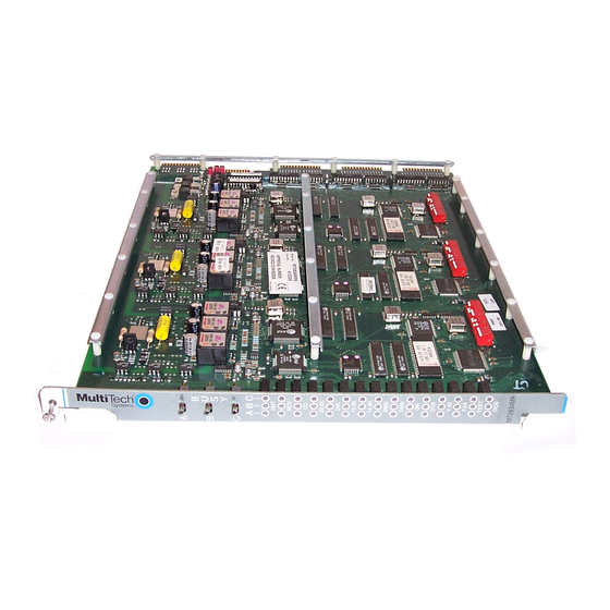
Page 104: Appendix Lmt2834Mri Pc Board
PN 88300150 Appendix L MT2834MRI PC Board MT2834MRI PCB Top 4/3/01... - Page 105 PN 88300150 MT2834MRI PCB (Chassis 2) 4/3/01...
- Page 106 PN 88300150 MT2834MRI Labels 4/3/01...