Table of Contents
Advertisement
Quick Links
Advertisement
Table of Contents

Related Manuals for Agilent Technologies 81150A


Summary of Contents for Agilent Technologies 81150A
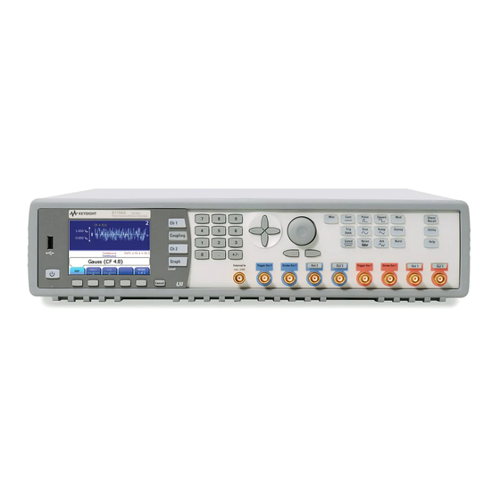
- Page 1 Agilent Pulse Function Arbitrary Noise Generator 81150A Getting Started Guide...
- Page 2 Assistance Notices This Agilent product has a warranty against Product maintenance agreements and other © Agilent Technologies, Inc. 2007 customer assistance agreements are available defects in material and workmanship for a period of three years from date of shipment. for Agilent products. For any assistance,...
- Page 3 Agilent Technologies Inc. Before Applying Power assumes no liability for the customer's failure to Verify that all safety comply with these precautions are taken. The requirements.
- Page 4 connected to the ac power repaired by qualified mains through a grounded service personnel. power cable, with the Services and Support ground wire firmly connected to an electrical Any adjustment, ground (safety ground) at maintenance, or repair of the power outlet. Any this product must be interruption of the performed by qualified...
- Page 5 Safety Symbols on Instruments General Recycling Mark for Indicates warning or caution. If Notice for European Community: plastic parts used in the product. you see this symbol on a product, This product complies with the you must refer to the manuals for relevant European legal specific Warning or Caution Directives: EMC Directive...
- Page 6 Introduction...
-
Page 7: Table Of Contents
Contents Contents Contents................................7 Introduction............................9 Installing the 81150A .......................... 10 The Front Panel..........................11 The Front-Panel Display at a Glance..................14 2.2.1 Menu Mode........................14 2.2.2 Graph Mode ........................15 The Rear Panel..........................16 Getting Started ............................ 17 Setting up a Clock Signal ......................18 Setting up a Pulse Signal ...................... - Page 8 Contents Operating Environment....................... 98 Cleaning Recommendation......................99 81150A Getting Started Guide...
-
Page 9: Introduction
Introduction Introduction The Agilent Technologies 81150A is a 120 MHz synthesized Pulse Function Introduction Arbitrary Noise Generator with built-in arbitrary waveform and pulse capabilities. Check if the Agilent 81150A shipping container contains the following Standard standard deliverables: Deliverables The Agilent 81150A 120 MHz Pulse Function Arbitrary Noise... -
Page 10: Installing The 81150A
Introduction the 81150A via the user interface. For information on operating the 81150A via the Remote Interface, refer to the Remote Programming Reference chapter in the 81150A User Guide. The instrument executes the power-on selftest during the boot phase. If Switching On the there are errors, the instrument displays the power-on error messages. -
Page 11: The Front Panel
(software-controlled keys). The current function of each softkey is indicated in the corresponding box on the display. The More softkey switches to the next layer of softkeys on the current screen. Cancels the selection and helps you exit out of a screen. Cancel 81150A Getting Started Guide... - Page 12 Ch 2 Selection Channel Coupling Enables/disables the channel coupling. Refer to the 81150A User Guide for more information on Channel Coupling. Unlike all the other keys on the Front Panel, the Coupling key is not protruded or alleviated. It is flat and is embedded inside the instrument.
- Page 13 External Gated Internal Triggered Manual The MAN key can be used to manually trigger or gate the instrument. Refer to the 81150A User Guide for more information on the Trigger Modes. Waveform Types Includes standard waveforms and pre-defined arbitrary waveforms.
-
Page 14: The Front-Panel Display At A Glance
This section explains the Menu and the Graph mode as seen on the Front Introduction Panel of the 81150A. 2.2.1 Menu Mode This section explains the Menu as seen on the Front Panel of the 81150A. Introduction 81150A Getting Started Guide... -
Page 15: Graph Mode
To enter the Graph mode, press the key. To exit, press the key again. Not all screens do have a graphical representation. Note The trigger mode screen will always be in textual mode, even if graph mode is enabled. 81150A Getting Started Guide... -
Page 16: The Rear Panel
A USB Host Connector is used to connect external USB storage device for storing instrument settings or software updates. The following figure shows the rear panel view of the 81150A. USB Interface Connector (Host type for external mass memory) USB Interface Connector (device type for remote programming) -
Page 17: Getting Started
Getting Started The intention of this chapter is to give the necessary steps to set up generic Introduction signals for first-time users of the 81150A. This chapter provides examples for the following types of signals: Setting up a Clock Signal... -
Page 18: Setting Up A Clock Signal
Getting Started Setting up a Clock Signal To set up a continuous clock signal with 50 MHz frequency, a duty cycle of Task 50%, a high Level of 2.5 V and a low level of 0.0 V. 81150A Getting Started Guide... - Page 19 Pressing the Period softkey selects period and pressing it again Important Tip toggles to Frequency softkey. If the Frequency softkey is already selected, do not press it again as it will toggle to the Period softkey. 81150A Getting Started Guide...
- Page 20 Knob. From the various available options, choose the desired unit by simply pressing it. The value of Duty Cycle is set to 50% by default. Therefore, there is Selecting Duty no need to change it. Cycle 81150A Getting Started Guide...
- Page 21 This can be done by navigating to the field using the navigation keys, Selecting the Ampl or by pressing the Ampl or Offset softkey. or Offset voltage Press the Ampl or Offset softkey again and then select High/Low by Switch to pressing the corresponding softkey. High/Low Level representation 81150A Getting Started Guide...
- Page 22 Setting the High navigation keys. Level Set the value to 2.5 V. Use the numeric keypad, or the navigation cursor and rotary knob to set the values. Select the appropriate unit shown in the following screen. 81150A Getting Started Guide...
- Page 23 #:FREQuency2 50MHZ #:FUNCtion2:SQUare:DCYCle 50 # Set the high level to 2.5 Volts, the low level to 0.0 Volts. :VOLTage1:HIGH 2.5V :VOLTage1:LOW 0V # Enable the output 1 and the complement output 1. :OUTput1 ON :OUTput1:COMPlement ON 81150A Getting Started Guide...
- Page 24 Getting Started The following image shows the signal as displayed on the Agilent 54810A Oscilloscope Infiniium Oscilloscope. Use the Trigger Out to trigger the scope. screen-shot 81150A Getting Started Guide...
-
Page 25: Setting Up A Pulse Signal
To set up a continuous pulse signal with 20 ns period, a width of 10 ns, a Task high Level of 3.3 V and a low level of 0.0 V. Pulse Width = 10 ns 3.3 V 0.0 V Period = 20 ns 81150A Getting Started Guide... - Page 26 The Continuous trigger mode is enabled by default. Therefore, we only need to select a Pulse waveform. To select a Pulse waveform, simply press the Pulse key given on the Front Panel. This brings you to the screen shown below. 81150A Getting Started Guide...
- Page 27 Period softkey. Set the value of the Period to 20 ns. Frequency For setting the value, you can use the Numeric Keypad or the Rotary Knob. From the various available options, choose the desired unit by simply pressing it. 81150A Getting Started Guide...
- Page 28 The default value is set to Width although the Width softkey contains Width, Duty Cycle, and Trail Delay representations. For setting the value, you can use the Numeric Keypad or the Rotary Knob. From the various available options, choose the desired unit by simply pressing it. 81150A Getting Started Guide...
- Page 29 For setting the value, you can use the Numeric Keypad or the Rotary Knob. To set the value of Lead Edge in %, press the Lead Edge softkey again. From the various available options, choose the desired unit by simply pressing it. 81150A Getting Started Guide...
- Page 30 Set the value to 5 ns. For setting the value, you can use the Numeric Keypad or the Rotary Knob. Press the Trail Edge softkey again to choose a different unit as shown in the subsequent screenshot. 81150A Getting Started Guide...
- Page 31 Selecting the unit pressing it. Select the amplitude or offset voltage value. This can be done by Selecting the Ampl navigating to the field using the navigation keys, or by pressing the or Offset Ampl or Offset softkey. 81150A Getting Started Guide...
- Page 32 Setting the Low navigation keys. Level Set the value to 0.0 V. Use the numeric keypad, or the navigation cursor and rotary knob to set the values. Select the appropriate unit shown in the following screen. 81150A Getting Started Guide...
- Page 33 Setting the High navigation keys. Level Set the value to 3.3 V. Use the numeric keypad, or the navigation cursor and rotary knob to set the values. Select the appropriate unit shown in the following screen. 81150A Getting Started Guide...
- Page 34 :PULSe:TRANsition1:TRAiling:AUTO OFF :PULSe:TRANsition1:TRAiling 5NS # Set the high level to 3.3 Volts, the low level to 0.0 Volts. :VOLTage1:HIGH 3.3V :VOLTage1:LOW 0V # Enable the output 1 and the complement output 1. :OUTput1 ON :OUTput1:COMPlement ON 81150A Getting Started Guide...
- Page 35 Getting Started The following image shows the signal as displayed on the Agilent 54810A Oscilloscope Infiniium Oscilloscope. Use the Trigger Out to trigger the scope. screen-shot 81150A Getting Started Guide...
-
Page 36: Setting Up A Continuous Burst
Getting Started Setting up a Continuous Burst To set up a continuous burst signal with 500 ns period, Pulse width of 100 Task ns and a burst length of 4 cycles. 81150A Getting Started Guide... - Page 37 Period softkey. Set the value of the Period to 500ns. For setting the value, you can use the Numeric Keypad or the Rotary Knob. From the various available options, choose the desired unit by simply pressing it. 81150A Getting Started Guide...
- Page 38 From the various available options, choose the desired unit by simply pressing it. Press the Burst key to select Burst. Setting the Burst Set the Burst Length to 4 using the numeric keypad or the navigation length keys. 81150A Getting Started Guide...
- Page 39 # Settings are programmed for output 1. :PULSe:PERiod1 500NS :PULSE:WIDTh1 100NS # enable burst mode and set the burst length to 4 :TRIGger1:COUNt 4 # Enable the output 1 and the complement output 1. :OUTput1 ON :OUTput1:COMPlement ON 81150A Getting Started Guide...
- Page 40 Getting Started The following image shows the signal as displayed on the Agilent 54810A Oscilloscope Infiniium Oscilloscope. Use the Strobe Out to trigger the scope. screen-shot 81150A Getting Started Guide...
-
Page 41: Setting Up A Triggered Burst
To set up a burst signal with a burst repetition of 5 µs. The burst repetition Task is generated by using the internal trigger source. The pulses are set to a period of 500 ns and width of 100 ns. Each burst contains 4 pulses. 81150A Getting Started Guide... - Page 42 Period softkey. Set the value of the Period to 500ns. For setting the value, you can use the Numeric Keypad or the Rotary Knob. From the various available options, choose the desired unit by simply pressing it. 81150A Getting Started Guide...
- Page 43 Press the Width softkey again to toggle to the different representations of Width: Width, Duty Cycle, and Trail Delay. From the various available options, choose the desired unit by simply pressing it. 81150A Getting Started Guide...
- Page 44 Now press the Internal Frequency softkey twice to toggle to Internal Setting the Internal Period. Set the Internal Period to 5 µs. Period From the various available options, choose the desired unit by simply pressing it. 81150A Getting Started Guide...
- Page 45 Press the Burst key to select Burst. Setting the Burst Set the Burst Length to 4 cycles. Use the navigation cursor and rotary length knob, or the cursor keys and rotary knob to set the value. 81150A Getting Started Guide...
- Page 46 # Switch to triggered mode and select the internal # trigger source :ARM:SENSe1 EDGE :ARM:SOURce1 INT2 # enable burst mode and set the burst length to 4 :TRIGger1:COUNt 4 # Enable the output 1 and the complement output 1. :OUTput1 ON :OUTput1:COMPlement ON 81150A Getting Started Guide...
- Page 47 Getting Started The following image shows the signal as displayed on the Agilent 54810A Oscilloscope Infiniium Oscilloscope. Use the Strobe Out to trigger the scope. screen-shot 81150A Getting Started Guide...
-
Page 48: To Output A Modulated Waveform
To output a modulated waveform with a continuous sine wave. The carrier Task frequency is 1.5 KHz. The modulation type is AM, AM source as Internal, AM depth of 100%, AM frequency as 100 Hz, and AM shape as Sine. 81150A Getting Started Guide... - Page 49 Press the Frequency softkey to select frequency. Set the value to 1.5 KHz. For setting the value, you can use the Numeric Keypad or the Rotary Knob. From the various available options, choose the desired unit by simply pressing it. 81150A Getting Started Guide...
- Page 50 AM Frequency is set to 100 Hz. All these settings exist by default. Therefore, we do not make any changes to these settings for this example. Let’s have a look at our current screen now. 81150A Getting Started Guide...
- Page 51 # Note: Since all the settings below are equal to the defaults, this step could be skipped. :AM1:DEPTh 100 :AM1:SOURce INT :AM1:INTernal:FREQuency 100HZ :AM1:INTernal:FUNCtion SIN # Enable AM :AM1:STATe ON # Enable the output 1 and the complement output 1. :OUTput1 ON :OUTput1:COMPlement ON 81150A Getting Started Guide...
- Page 52 Getting Started The following image shows the signal as displayed on the Agilent 54810A Oscilloscope Infiniium Oscilloscope. Use the Strobe Out to trigger the scope. screen-shot 81150A Getting Started Guide...
-
Page 53: To Output An Fsk Waveform
To output an FSK waveform with a continuous sine wave, modulation type Task as FSK, FSK source as Internal, carrier frequency of 1 MHz, Amplitude of 5Vpp, FSK Rate of 450 KHz, FSK Hop Frequency of 5 MHz. 81150A Getting Started Guide... - Page 54 Press the Ampl softkey to set the Amplitude to 5 Vpp. From the various available options, choose the desired unit by simply pressing For setting the value, you can use the Numeric Keypad or the Rotary Knob. 81150A Getting Started Guide...
- Page 55 Press the Modulation Type softkey and select FSK. The FSK Source is set to Internal by default. Therefore, do not change Setting the FSK source Press the Hop Frequency softkey and set the value to 5 MHz. Setting the Hop Frequency 81150A Getting Started Guide...
- Page 56 Getting Started Press the FSK Rate softkey and set the value to 450 KHz. Setting the FSK Rate 81150A Getting Started Guide...
- Page 57 # - internal FSK source # - FSK Rate 450 kHz :FSK1:FREQuency 5MHZ :FSK1:SOURce INT :FSK1:INTernal:RATE 450KHZ # Enable FSK :FSK1:STATe ON # Enable the output 1 and the complement output 1. :OUTput1 ON :OUTput1:COMPlement ON 81150A Getting Started Guide...
- Page 58 Getting Started The following image shows the signal as displayed on the Agilent 54810A Oscilloscope Infiniium Oscilloscope. Use the Strobe Out to trigger the scope. screen-shot 81150A Getting Started Guide...
-
Page 59: To Output A Frequency Sweep
To output a Frequency Sweep To set up a Frequency Sweep with Start Frequency at 1 kHz and Stop Task Frequency at 8 kHz, Carrier Sinewave of 5 Vpp, Sweep Time of 2 ms, and sweep type as Linear. 81150A Getting Started Guide... - Page 60 1. The Sine waveform is set by default. Press the Ampl softkey to set the Amplitude of the carrier sinewave to 5Vpp. For setting the value, you can use the Numeric Keypad or the Rotary Knob. 81150A Getting Started Guide...
- Page 61 The Sweep Type can be Linear or Logarithmic. Depending upon your requirements, you can select the appropriate one. Press the Start Frequency softkey to set the start frequency value. Setting the Start Set the value to 1 kHz. Frequency 81150A Getting Started Guide...
- Page 62 Press the Stop Frequency softkey to set the stop frequency value. Setting the Stop Set the value to 8 kHz. Frequency Press the Sweep Time softkey to set the sweep duration value. Set Setting the Sweep the value to 2 ms. Time 81150A Getting Started Guide...
- Page 63 # Select linear sweep spacing :SWEep1:SPACing LINear # Enable frequency sweep :SWEep1:STATe ON # Set the output amplitude to 5 Vpp :VOLTage1 5VPP # Enable the output 1 and the complement output 1. :OUTput1 ON :OUTput1:COMPlement ON 81150A Getting Started Guide...
- Page 64 Getting Started The following image shows the signal as displayed on the Agilent 54810A Oscilloscope Infiniium Oscilloscope. Use the Strobe Out to trigger the scope. screen-shot 81150A Getting Started Guide...
-
Page 65: Setting Up A Triggered Frequency Sweep
Setting up a Triggered Frequency Sweep To set up a triggered linear Sweep with Sinewave of 5 Vpp, Start frequency Task at 1 kHz, Stop Frequency at 8 kHz, Sweep Time of 2 ms, and Internal Period of 5 ms. 81150A Getting Started Guide... - Page 66 1. The Sine waveform is set by default. Press the Ampl softkey to set the Amplitude of the carrier sinewave to 5Vpp. For setting the value, you can use the Numeric Keypad or the Rotary Knob. 81150A Getting Started Guide...
- Page 67 The Sweep Type can be Linear or Logarithmic. Depending upon your requirements, you can select the appropriate one. Press the Start Frequency softkey to set the start frequency value. Setting the Start Set the value to 1 kHz. Frequency 81150A Getting Started Guide...
- Page 68 Press the Stop Frequency softkey to set the stop frequency value. Setting the Stop Set the value to 8 kHz. Frequency Press the Sweep Time softkey to set the sweep duration value. Set Setting the Sweep the value to 2 ms. Time 81150A Getting Started Guide...
- Page 69 Press the Source softkey to select Internal as the Trigger source. Trigger Source Now press the Internal Frequency softkey twice to toggle to Internal Setting the Internal Period. Set the Internal Period to 5 ms. Period 81150A Getting Started Guide...
- Page 70 # Set the internal trigger period to :ARM:PERiod1 5ms # Switch to triggered mode and select the internal # trigger source :ARM:SENSe1 EDGE :ARM:SOURce1 INT2 # Enable the output 1 and the complement output 1. :OUTput1 ON :OUTput1:COMPlement ON 81150A Getting Started Guide...
- Page 71 Getting Started The following image shows the signal as displayed on the Agilent 54810A Oscilloscope Infiniium Oscilloscope. Use the Strobe Out to trigger the scope. screen-shot 81150A Getting Started Guide...
-
Page 72: Coupling Between Channels
Refer to the 81150A User Guide for more information. Let’s set different values for different parameters on both channels one-by-one, and enable coupling. - Page 73 For setting the value, you can use the Numeric Keypad or the Rotary Amplitude Knob. Press the Offset softkey or use the navigation key to set the Offset. Setting the Offset Set the offset to 1 Vdc. 81150A Getting Started Guide...
-
Page 74: Settings For Channel 2
Press the Frequency softkey to select frequency. Set the value to 2 MHz. For setting the value, you can use the Numeric Keypad or the Rotary Knob. From the various available options, choose the desired unit by simply pressing it. 81150A Getting Started Guide... - Page 75 Press the Ampl softkey and set the value to 3 Vpp. Setting the For setting the value, you can use the Numeric Keypad or the Rotary Amplitude Knob. The Offset is set to 0 VDC by default; therefore we do not change it. Setting the Offset 81150A Getting Started Guide...
- Page 76 Getting Started Press the Trig key to enable the trigger mode. Enable the Trigger mode Press the Burst key and set the burst length to 5. Set the Burst length 81150A Getting Started Guide...
- Page 77 Channel 1 Press the Coupling key. This enables coupling of both channels. Enable Coupling Since Channel 1 is currently selected, the setting of Channel 2 will be adjusted to match the settings of Channel 1. 81150A Getting Started Guide...
- Page 78 Press the Frequency softkey and change the frequency from 1 MHz Change Frequency to 2 MHz. Next, press the Delay softkey and change the value of and Delay Delay from 10 ns to 20 ns. 81150A Getting Started Guide...
- Page 79 You will notice that the changes done on Channel 2 (in terms of Channel 1 again changing the frequency) get reflected on Channel 1 as both channels are coupled. But, the delay on Channel 1 is still at the initial value of 0.0 ns. 81150A Getting Started Guide...
- Page 80 Getting Started # This example requires a 2 channel 81150A to run without errors. Programming Example # Reset the instrument to start from a defined, default status. *RST # Switch off the automatic display update to increase programming # speed...
- Page 81 # change frequency and delay on channel 2 :FREQuency2 2MHZ :PULSe:DELay2 20NS # now the setting on channel 1 has changed to # - Frequency 2 MHz # disable channel coupling (can be done on any channel) :TRACk:CHANnel2 OFF 81150A Getting Started Guide...
-
Page 82: Adding Up Channel 1 And Channel 2
For Channel 2: Continuous Pulse with frequency 1 MHz, width 10 ns, delay 200 ns, lead edge 2.5 ns, trail edge 2.5 ns, offset 0 V and amplitude 2 Vpp. This example requires a 2 channel version of the 81150A. 81150A Getting Started Guide... -
Page 83: Settings For Channel 1
To select a Pulse waveform, simply press the Pulse key given on the Front Panel. By default, the Frequency is already set to 1 MHz, and the Delay to Selecting the 0 seconds, therefore we do not change these values. Frequency and Delay 81150A Getting Started Guide... - Page 84 For setting the value, you can use the Numeric Keypad or the Rotary Knob. Press the Lead Edge softkey to set the Lead Edge value. Press it Setting the Lead again to set the value of Lead Edge in %. Set the value to 75%. Edge 81150A Getting Started Guide...
- Page 85 Set the value of Trail Edge to 50%. Press the Trail Edge softkey again to choose a different unit for different requirements. Press the Ampl softkey or use the navigation key to set the Setting the Amplitude. Set the amplitude to 3Vpp. Amplitude 81150A Getting Started Guide...
- Page 86 Setting the Offset change it. Press the Coupling key to enable Channel Coupling. This will set Enable Channel Channel 2 to continuous Pulse mode and ensure that both channels Coupling are locked in phase and frequency. 81150A Getting Started Guide...
-
Page 87: Settings For Channel 2
By default, the Frequency is already set to 1 MHz, therefore we do Selecting the not change it. Frequency Press the Delay softkey and set the value to 200 ns. Setting Delay For setting the value, you can use the Numeric Keypad or the Rotary Knob. 81150A Getting Started Guide... - Page 88 For setting the value, you can use the Numeric Keypad or the Rotary Knob. By default, the Lead Edge/Trail Edge values are set to 2.5 ns, Setting the Lead therefore we do not change these values. Edge and Trail Edge 81150A Getting Started Guide...
- Page 89 Press the Ampl softkey or use the navigation key to set the Setting the Amplitude. Set the amplitude to 2Vpp. Amplitude By default, the Offset is set to 0 Vdc, therefore we do not change the Setting the Offset values. 81150A Getting Started Guide...
- Page 90 Getting Started To perform Channel Addition: For Channel Addition Press the Ch 1 key. Press Utility key, Output Setup softkey and then Channel Add softkey. Press the Channel Add softkey and enable Added at Output 1. 81150A Getting Started Guide...
- Page 91 Getting Started # This example requires a 2 channel 81150A to run without errors. Programming Example # Reset the instrument to start from a defined, default status. *RST # Switch off the automatic display update to increase programming # speed :DISPlay OFF # Enable channel coupling.
- Page 92 # - Amplitude 2Vpp :PULSe:DELay2 200nS :PULSe:WIDTh2 10NS :PULSe:TRANsition2 2.5NS :PULSe:TRANsition2:TRAiling 2.5NS :VOLT2:OFFSet 0V :VOLT2 2VPP # Enable channel addition :CHANnel:MATH PLUS # Enable the output 1 and the complement output 1. :OUTput1 ON :OUTput1:COMPlement ON 81150A Getting Started Guide...
- Page 93 Getting Started The following image shows the signal as displayed on the Agilent 54810A Oscilloscope Infiniium Oscilloscope. Use the Trigger Out to trigger the scope. screen-shot 81150A Getting Started Guide...
-
Page 94: Installation And Maintenance
Installation and Maintenance Installation and Maintenance This chapter explains how to install and maintain the 81150A. It covers the Introduction following: Options and Accessories Power Requirements Ventilation Requirements Thermal Protection Battery Operating Environment Cleaning Recommendation Options and Accessories Agilent Part number 5063-9219. -
Page 95: Power Requirements
400 Hz. The maximum power consumption is 180 VA with all options installed. When the instrument is switched on the power supply adapts automatically to the applied AC power (Auto Selection) and monitors the AC power range during operation. 81150A Getting Started Guide... -
Page 96: Ventilation Requirements
When the temperature exceeds approximately 80°C the overheating detection switches off the instrument for safety reasons. For reliability it is recommended to send instruments with broken or defective fans immediately to Agilent Service for repair. 81150A Getting Started Guide... -
Page 97: Battery
Installation and Maintenance Battery The 81150A contains one lithium battery. The typical life time of this battery Introduction depends on the environmental temperature. If the environmental temperature is 25° C, then the battery lasts for 20 years. If the environmental temperature is 55° C, then the battery lasts only for 3 years. - Page 98 Do not operate the instrument in the presence of flammable gases, fumes or powders. Operation of any electrical instrument in such an environment constitutes a definite safety hazard. 81150A Getting Started Guide...
- Page 99 Installation and Maintenance Cleaning Recommendation To prevent electrical shock, disconnect the instrument from mains before Warning cleaning. Use a dry cloth or one slightly dampened with water to clean external case parts. Do not attempt to clean internally. 81150A Getting Started Guide...
- Page 100 Installation and Maintenance 81150A Getting Started Guide...
- Page 102 Copyright Agilent Technologies 2007 First Edition, November 2007 Printed in Germany...
- Page 103 Installation and Maintenance 81150A Getting Started Guide...