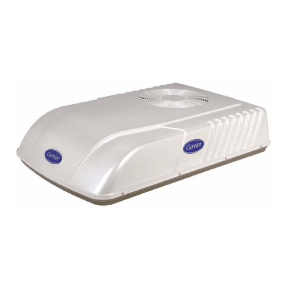
Summary of Contents for Carrier AirV 68RV11112A
- Page 1 Transport Air Conditioning Transport Air Conditioning GRN/YEL EVAP. SERVICE MANUAL MODEL AirV Rooftop Air Conditioning Systems T--298 Rev G...
- Page 2 SERVICE MANUAL AirV AIR CONDITIONING AND HEATING EQUIPMENT MODELS 68RV11112A 68RV11122A 68RV11302A 68RV14102A 68RV14103A 68RV14113A 68RV14123A 68RV15102A 68RV15103A...
- Page 3 SAFETY SUMMARY GENERAL SAFETY NOTICES The following general safety notices supplement the specific warnings and cautions appearing elsewhere in this manual. They are recommended precautions that must be understood and applied during operation and maintenance of the equipment covered herein. The general safety notices are presented in the following three sections labeled: First Aid, Operating Precautions and Maintenance Precautions.
- Page 4 SPECIFIC WARNING AND CAUTION STATEMENTS The statements listed below are applicable to the refrigeration unit and appear elsewhere in this manual. These recommended precautions must be understood and applied during operation and maintenance of the equipment covered herein. SPECIFIC WARNINGS AND CAUTIONS WARNING Be sure to observe warnings listed in the safety summary in the front of this manual before performing maintenance on the AirV system...
- Page 5 CAUTION Do not use carbon tetrachloride, solvents, or waxes containing solvents to clean plastic sec- tions. CAUTION Coil fins are sharp. Use care when removing the cover form the base pan to avoid personal injury. CAUTION The change from Fahrenheit to Celsius will be permanent. It cannot be changed back to Fahr- enheit.
- Page 6 TABLE OF CONTENTS PARAGRAPH NUMBER Page SPECIFIC WARNING AND CAUTION STATEMENTS ......... . . SPECIFIC WARNINGS AND CAUTIONS .
- Page 7 TABLE OF CONTENTS - - Continued: SERVICE AND MAINTENANCE ..............3- -1 PREVENTATIVE MAINTENANCE .
- Page 8 TABLE OF CONTENTS - - Continued: THERMOSTAT INSTALLATION AND START--UP INSTRUCTIONS (WALL MOUNTED) ..3--17 3.8.1 Introduction ..............3--17 3.8.2 Installation .
- Page 9 LIST OF FIGURES - - Continued: Figure 3--1 Filter Removal -- Free Blow ............3--1 Figure 3--2 Ceiling Grill -- Free Blow .
- Page 10 LIST OF FIGURES - - Continued: Figure 3--40 Remote Control PCB (FR9 Location) ..........3--16 Figure 3--41 Wall Thermostat Wiring Diagram -- Cool Only Model .
- Page 11 This manual contains service instructions and electrical The letter Y and all the numbers after it designates the data for the AirV, Carrier Transport Air Conditioning’s unit serial number. Example: Y43210 Recreational Vehicle air conditioning unit. The AirV units are two piece systems, consisting of the A serial number of 1303Y12345 designates that the unit Upper Unit and the Ceiling unit.
- Page 12 Table 1- -1 Model Chart UPPER UNIT (ROOF) MODEL NUMBER PART NUMBER CONFIGURATION VOLTAGE AMPS COLOR 99--00468--00 STANDARD A/C 115/1/60 12.8 WHITE 99--00468--01 STANDARD A/C 115/1/60 12.8 IVORY 68RV14102A 99--00469--20 STANDARD A/C 115/1/60 12.8 BLACK 99--00468--02 STANDARD A/C 220/1/50 WHITE 5.3 COOL 68RV11302A 99--00468--03...
- Page 13 TABLE 1- -2 MODEL CHART CEILING UNIT MODEL NUMBER PART NUMBER VOLTAGE COLOR OPTIONS INTERFACE 99--00469--00 115/1/60 White Cool Only Free--Blow 68RV0010AA 99--00469--01 115/1/60 Ivory Cool Only Free--Blow 99--00469--02 115/1/60 White Heat/Cool Free--Blow 68RV0010BA 99--00469--03 115/1/60 Ivory Heat/Cool Free--Blow 68RV0010KA 99--00469--06 115/1/60 (12VDC) White...
- Page 14 TABLE 1- -3 ADDITIONAL SUPPORT MANUALS MANUAL- -FORM NO. EQUIPMENT COVERED TYPE OF MANUAL (For) PART NO. 99--00469--00 71LC6A5431A AirV 115 Volts--Free Blow (Cool Only) Owner’s Guide 99--00469--01 99--00469--02 71LH6A5407A AirV 115 Volts--Free Blow (Heat--Cool) Owner’s Guide 99--00469--03 99--00469--06 71LD6A54070 AirV 115 Volts--Ducted (Cool Only) Owner’s Guide 99--00469--08...
- Page 15 Cover Compressor Condenser Base Pan Evaporator Figure 1- -2 Roof Unit (Standard) Component Identification 1--5 T--298 10/09...
- Page 16 Ceiling Panel Assembly Control Assembly Ceiling Grill Assembly Control Box Cover Figure 1- -3 Ceiling Unit Component Identification (Free- -Blow) 1--6 10/09 T--298...
- Page 17 Cover Assembly Condenser Coil Scroll Assembly -- Upper Scroll Assembly -- Lower Condenser Fan Evaporator Coil Condenser Motor 10. Compressor Evaporator Motor 11. Base Pan Assembly Evaporator Blower Wheel See Figure 1--3 for Ceiling Package (Free-- Blow) Figure 1- -4 Component Identification - - Low Profile - - Upper Unit 1--7 T--298 10/09...
- Page 18 Telescoping Divider (3 different sizes available) Remote Control Assembly Divider Assembly Remote Control Bracket Assembly Frame Panel, Insulation Assembly Filter Assemblies (2) Control Box Assembly 10. PCB Cover Control Box Cover 11. PCB Main Assembly Suction Packing Assembly 12. PCB Display Figure 1- -5 Component Listing- -Ceiling Unit For Ducted Systems 1--8 10/09...
- Page 19 1.4 SYSTEM (UNIT) INSTALLED DIMENSIONS Refer to Figure 1--6 thru Figure 1--9 for installation dimensions of Standard & Low Profile Upper Units & Ducted & Free--Blow Ceiling units. 14” by 14” 10.3” 16.7” Opening 41.0” ROOF UNIT - - TOP VIEW - - STANDARD 3.6”...
- Page 20 10.3” 16.7” 14” OPENING 1.65” 1.65” STANDARD ROOF - - DUCTED CEILING 10.3” 16.7” 14” OPENING 8.15” 3.45” STANDARD ROOF - - FREEBLOW CEILING Figure 1- -7 Unit Dimensions - - Standard - - Side View - - Roof + Ceiling 1--10 10/09 T--298...


