Advertisement
Quick Links
707C--K
Legacy™13.4 SEER2 Single-Packaged Air
Conditioner System with Puron®
(R-410A) Refrigerant
Single Phase 2-5 Nominal Tons (Sizes 24-60)
Three Phase 3-5 Nominal Tons (Sizes 36-60)
IMPORTANT: Effective January 1, 2015, all split system and packaged
air conditioners must be installed pursuant to applicable regional
efficiency standards issued by the Department of Energy.
NOTE: Read the entire instruction manual before starting the
installation.
NOTE:
Installer: Make sure the Owner's Manual and Service
Instructions are left with the unit after installation.
Table of Contents
Safety Considerations . . . . . . . . . . . . . . . . . . . . . . . . . . . . . . . . . . . . . . . 1
Introduction. . . . . . . . . . . . . . . . . . . . . . . . . . . . . . . . . . . . . . . . . . . . . . . 2
Receiving and Installation . . . . . . . . . . . . . . . . . . . . . . . . . . . . . . . . . . . 2
Pre-Start-up . . . . . . . . . . . . . . . . . . . . . . . . . . . . . . . . . . . . . . . . . . . . . . 12
Start-up . . . . . . . . . . . . . . . . . . . . . . . . . . . . . . . . . . . . . . . . . . . . . . . . . 12
Maintenance . . . . . . . . . . . . . . . . . . . . . . . . . . . . . . . . . . . . . . . . . . . . . 25
Troubleshooting . . . . . . . . . . . . . . . . . . . . . . . . . . . . . . . . . . . . . . . . . . 28
Start-up Checklist . . . . . . . . . . . . . . . . . . . . . . . . . . . . . . . . . . . . . . . . . 28
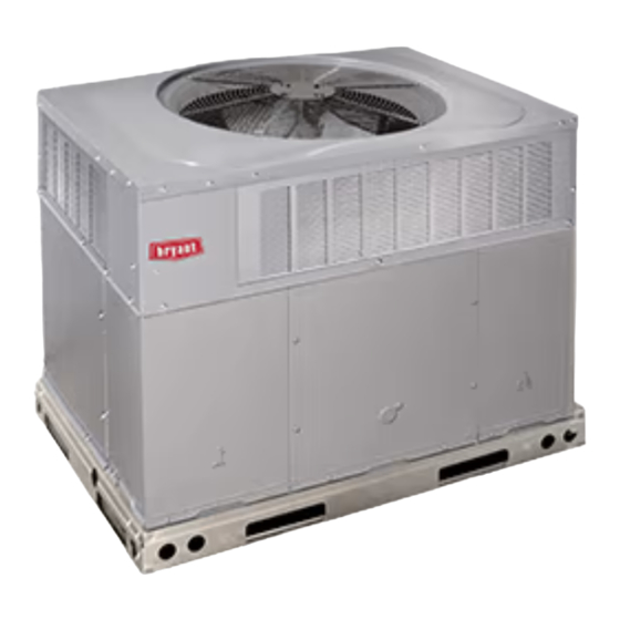
Fig. 1 - Unit 707C
Safety Considerations
Improper installation adjustment, alteration, service, maintenance, or use
can cause explosion, fire, electrical shock, or other conditions which
may cause death, personal injury, or property damage. Consult a
qualified installer, service agency, or your distributor or branch for
information or assistance. The qualified installer or agency must use
factory-authorized kits or accessories when modifying this product Refer
to the individual instructions packaged with the kits or accessories when
installing.
Follow all safety codes. Wear safety glasses, protective clothing, and
work gloves. Use quenching cloth for brazing operations. Have a fire
extinguisher available. Read these instructions thoroughly and follow all
warnings or cautions included in literature and attached to the unit.
Consult local building codes, the current editions of the National
Electrical Code (NEC) NFPA 70.
Installation Instructions
A09033
In Canada refer to the current editions of the Canadian electrical Code
CSA C22.1.
Recognize safety information. This is the safety-alert symbol
you see this symbol on the unit and in instructions or manuals, be alert to
the potential for personal injury. Understand these signal words;
DANGER, WARNING, and CAUTION. These words are used with the
safety-alert symbol. DANGER identifies the most serious hazards which
will result in severe personal injury or death. WARNING signifies
hazards which could result in personal injury or death. CAUTION is
used to identify unsafe practices which may result in minor personal
injury or product and property damage. NOTE is used to highlight
suggestions which will result in enhanced installation, reliability, or
operation.
WARNING
!
ELECTRICAL SHOCK HAZARD
Failure to follow this warning could result in personal injury or death.
Before installing or servicing system, always turn off main power to
system and install lockout tag. There may be more than one disconnect
switch. Turn off accessory heater power switch if applicable.
WARNING
!
PERSONAL INJURY AND ENVIRONMENTAL HAZARD
Failure to relieve system pressure could result in personal injury and/or
death.
1.
Relieve pressure and recover all refrigerant before servicing
existing equipment, and before final unit disposal. Use all
service ports and open all flow-control devices, including
solenoid valves.
2.
Federal regulations require that you do not vent refrigerant into
the atmosphere. Recover during system repair or final unit
disposal.
!
CUT HAZARD
Failure to follow this caution may result in personal injury.
When removing access panels (see
functions inside your unit, be aware of sharp sheet metal parts and
screws. Although special care is taken to reduce sharp edges to a
minimum, be extremely careful and wear appropriate clothing, safety
glasses and gloves when handling parts or reaching into the unit.
CAUTION
Fig.
20) or performing maintenance
. When
Advertisement

Related Manuals for Bryant Legacy 707C K Series


Summary of Contents for Bryant Legacy 707C K Series
-
Page 1: Table Of Contents
707C--K Legacy™13.4 SEER2 Single-Packaged Air Conditioner System with Puron® (R-410A) Refrigerant Single Phase 2-5 Nominal Tons (Sizes 24-60) Three Phase 3-5 Nominal Tons (Sizes 36-60) Installation Instructions IMPORTANT: Effective January 1, 2015, all split system and packaged In Canada refer to the current editions of the Canadian electrical Code air conditioners must be installed pursuant to applicable regional CSA C22.1. -
Page 2: Introduction
Step 2 – Provide Unit Support WARNING IMPORTANT: The unit must be secured to the curb by installing screws through the bottom of the curb flange and into the unit base rails. PERSONAL INJURY AND PROPERTY DAMAGE When installing large base units onto the common curb, the screws must HAZARD be installed before allowing the full weight of the unit to rest on the curb. - Page 3 707C--K: Installation Instructions A221492 Fig. 2 – 24-30 Unit Dimensions Manufacturer reserves the right to change, at any time, specifications and designs without notice and without obligations.
- Page 4 707C--K: Installation Instructions A221493 Fig. 3 – 36-48 Unit Dimensions Manufacturer reserves the right to change, at any time, specifications and designs without notice and without obligations.
- Page 5 707C--K: Installation Instructions SMALL/COMMON CURB SMALL SUPPLY BASE UNIT LARGE BASE RETURN UNIT UNIT PLACEMENT ON COMMON CURB SMALL OR LARGE BASE UNIT LARGE CURB A180216 UNIT CATALOG (small/common (large base) SIZE NUMBER base) IN. (mm) IN. (mm) (mm) IN. (mm) (mm) (mm) (mm)
- Page 6 707C--K: Installation Instructions 5.Insulated panels: 1-in. (25.4 mm) thick fiberglass 1 lb. density. Fig. 4 – Roof Curb Dimensions CAUTION - NOTICE TO RIGGERS PRUDENCE - AVIS AUX MANIPULATEUR ACCESS PANELS MUST BE IN PLACE WHEN RIGGING. PANNEAUX D'ACCES DOIT ÊTRE EN PLACE POUR MANIPULATION. Use top skid as spreader bar.
- Page 7 707C--K: Installation Instructions 1. Application of the lifter to the load, and adjustment of the lifts to After the unit is placed on the roof curb or mounting pad, remove the top adapt to various sizes or kinds of loads. skid.
- Page 8 707C--K: Installation Instructions IMPORTANT: Use flexible connectors between ductwork and unit to Adequately insulate and weatherproof all ductwork located prevent transmission of vibration. Use suitable gaskets to ensure outdoors. Insulate ducts passing through unconditioned space, and weather-tight and airtight seal. When electric heat is installed, use use vapor barrier in accordance with latest issue of Sheet Metal and Air Conditioning Contractors National Association (SMACNA) fireproof canvas (or similar heat resistant material) connector between...
- Page 9 707C--K: Installation Instructions CAUTION HIGH VOLTAGE POWER LEADS UNIT COMPONENT DAMAGE HAZARD POWER (SEE UNIT WIRING SUPPLY LABEL) Failure to follow this caution may result in damage to the unit being 3-PHASE SHOWN installed. 1-PHASE USES Make all electrical connections in accordance with NFPA 70 TWO POWER EQUIP GR LEADS...
- Page 10 707C--K: Installation Instructions Provide a drip loop before running wires through panel. Secure and strain relief all wires so that they do not interfere with operation of unit. If an accessory electric heater is installed, low voltage leads from heater must be connected to factory supplied control leads from Indoor Fan Board P4 connector.
- Page 11 707C--K: Installation Instructions Table 1 – Physical Data-Unit UNIT SIZE NOMINAL CAPACITY (ton) 2-1/2 3-1/2 SHIPPING WEIGHT lb. SHIPPING WEIGHT (kg) Scroll COMPRESSORS Quantity REFRIGERANT (R-410A) Quantity lb 5.75 10.0 Quantity (kg) REFRIGERANT METERING DEVICE Orifice ORIFICE ID in./mm .059 / 1.5 .063 / 1.60 .070 / 1.78 .073 / 1.85...
-
Page 12: Pre-Start-Up
707C--K: Installation Instructions Pre-Start-up Proceed as follows to locate and repair a refrigerant leak and to charge the unit: WARNING 1. Locate leak and make sure that refrigerant system pressure has been relieved and reclaimed from both high- and low-pressure ports. 2. - Page 13 707C--K: Installation Instructions attached to the inside of the compressor access panel. (See Fig. 18 This unit is factory-set up for use with a single cooling fan speed. In Subcool chart for units with TXV and superheat chart for units with addition, this unit has the field-selectable capability to run two different fixed orifice.) The chart includes the required liquid line temperature at cooling fan speeds: The rated cooling fan speed (350~400 CFM/Ton)
- Page 14 707C--K: Installation Instructions – interface board (IFB). Verify that static pressure is in the acceptable Table 3 – Color Coding for Indoor Fan Motor Leads range for the speed tap to be used for dehumidification cooling. Black = High Speed 7.
- Page 15 Table 4 – Dry Coil Air Delivery* - Horizontal and Downflow Discharge Sizes 24-60 ESP (in. W.C.) Unit Size Motor Speed Blue 0.07 0.08 0.08 0.09 Med-Low Pink 0.12 0.13 0.13 0.13 0.14 0.14 0.15 1080 1025 Medium** 0.21 0.22 0.23 0.23 0.24...
- Page 16 Table 4 – Dry Coil Air Delivery* - Horizontal and Downflow Discharge Sizes 24-60 (Continued) ESP (in. W.C.) Unit Size Motor Speed Blue 0.13 0.13 0.14 0.15 0.16 0.16 0.17 0.18 0.18 0.19 1201 1153 1107 1060 1012 Med-Low Pink 0.21 0.22 0.22...
- Page 17 Table 5 – Wet Coil Pressure Drop (IN. W.C.) Unit Standard CFM (SCFM) Size 1000 1100 1200 1300 1400 1500 1600 1700 1800 1900 2000 2100 2200 0.03 0.04 0.04 0.05 0.06 0.05 0.06 0.07 0.08 0.11 0.06 0.06 0.09 0.10 0.11 0.14...
- Page 18 707C--K: Installation Instructions A221589 Fig. 12 – Connection Wiring Diagram 208/230-1-60 Manufacturer reserves the right to change, at any time, specifications and designs without notice and without obligations.
- Page 19 707C--K: Installation Instructions A221590 Fig. 13 – Ladder Wiring Diagram 208/230-1-60 Manufacturer reserves the right to change, at any time, specifications and designs without notice and without obligations.
- Page 20 707C--K: Installation Instructions A221587 Fig. 14 – Connection Wiring Diagram 208/230-3-60 Manufacturer reserves the right to change, at any time, specifications and designs without notice and without obligations.
- Page 21 707C--K: Installation Instructions A221588 Fig. 15 – Ladder Wiring Diagram 208/230-3-60 Manufacturer reserves the right to change, at any time, specifications and designs without notice and without obligations.
- Page 22 707C--K: Installation Instructions A221585 Fig. 16 – Connection Wiring Diagram 460-3-60 Manufacturer reserves the right to change, at any time, specifications and designs without notice and without obligations.
- Page 23 707C--K: Installation Instructions A221586 Fig. 17 – Ladder Wiring Diagram 460-3-60 Manufacturer reserves the right to change, at any time, specifications and designs without notice and without obligations.
- Page 24 707C--K: Installation Instructions Superheat charging table is derived from optimum performance point. (95_F [35_C] outdoor ambient and (80_F [27_C] dry bulb; 67_F [19_C] wet bulb indoor condition.) Where a dash(--) appears do not attempt to check charge or charge unit under these conditions using the superheat method. (Weigh in method should be used.) A150625 Fig.
-
Page 25: Maintenance
707C--K: Installation Instructions Maintenance cooling season and twice during the heating season, or whenever the filter becomes clogged with dust and lint. To ensure continuing high performance, and to minimize the possibility Indoor Blower and Motor of premature equipment failure, periodic maintenance must be NOTE: All motors are pre-lubricated. - Page 26 707C--K: Installation Instructions FAN GRILLE MOTOR MOTOR SHAFT A08505 MAX DISTANCE BETWEEN TOP OF FAN GRILLE AND BOTTOM OF FAN BLADE “A” Size Fig. 19 – Fan Blade Position matter from the pan. Flush the pan and drain trough with clear water. Do not splash water on the insulation, motor, wiring, or air filter(s).
- Page 27 707C--K: Installation Instructions suspected malfunction has occurred, check each electrical component kPa). High pressure may be caused by a dirty condenser coil, failed fan with the proper electrical instrumentation. Refer to the unit wiring label motor, or condenser air recirculation. when making these checkouts.
-
Page 28: Troubleshooting
707C--K: Installation Instructions Rotary Compressor Liquid Line Filter Drier The 24 and 30 size units use a single cylinder rotary compressor. This The filter drier is specifically designed to operate with Puron (R-410A). compressor utilizes a rotor which is positioned eccentrically with respect Use only factory-authorized components. - Page 29 707C--K: Installation Instructions Table 10 – Troubleshooting Chart SYMPTOM CAUSE REMEDY Power failure Call power company Fuse blown or circuit breaker tripped Replace fuse or reset circuit breaker Defective contactor, transformer, control relay, or Replace component high-pressure, loss-of-charge or low-pressure switch Compressor and outdoor fan will not start Insufficient line voltage Determine cause and correct...
- Page 30 707C--K: Installation Instructions Start-Up Checklist (Remove and Store in Job Files) I. PRELIMINARY INFORMATION MODEL NO.: ____________________________________________ SERIAL NO.: ____________________________________________ DATE: __________________________________________________ TECHNICIAN: ___________________________________________ II. PRESTART-UP (Insert check mark in box as each item is completed) ( ) VERIFY THAT ALL PACKING MATERIALS HAVE BEEN REMOVED FROM UNIT ( ) REMOVE ALL SHIPPING HOLD DOWN BOLTS AND BRACKETS PER INSTALLATION INSTRUCTIONS ( ) CHECK ALL ELECTRICAL CONNECTIONS AND TERMINALS FOR TIGHTNESS ( ) CHECK THAT INDOOR (EVAPORATOR) AIR FILTER IS CLEAN AND IN PLACE...