Advertisement
Quick Links
June 2021© Massey GC1705 ROPS Cab Installation Manual
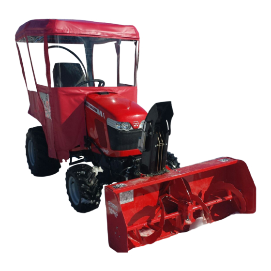
Massey Ferguson GC1705 ROPS Cab
* Shown with optional equipment *
www.tektite.ca
Please note: Cab is shown in photo with optional accessories.
Massey Ferguson GC1705 ROPS Cab
This ROPS cab is designed and built to fit the Massey Ferguson GC1705 and GC1715 tractor.
Designed and Built by:
Tektite Manufacturing Inc:
427 Buffalo Street
P.O. Box 639
Winkler, MB
R6W 4A8
Canada
PH: 204-331-3463
Fax: 204-331-4159
sales@tektite.ca
www.tektite.ca
One year standard product warranty provided by Tektite.
Advertisement

Related Manuals for MASSEY FERGUSON GC1715


Summary of Contents for MASSEY FERGUSON GC1715
- Page 1 Please note: Cab is shown in photo with optional accessories. Massey Ferguson GC1705 ROPS Cab This ROPS cab is designed and built to fit the Massey Ferguson GC1705 and GC1715 tractor. Designed and Built by: Tektite Manufacturing Inc: 427 Buffalo Street P.O.
- Page 2 DO NOT PROCEED FURTHER UNTIL YOU HAVE READ THE INFORMATION BELOW 1) Always wear personal protective equipment 2) A minimum of two people is necessary to safely install the cab 3) This ROPS cab is heavy. A lift assist device such as an overhead hoist or high lift forklift is required.
- Page 3 June 2021© Massey GC1705 ROPS Cab Installation Manual Tektite Manufacturing Incorporated thanks you for purchasing a Massey Ferguson GC1705 ROPS cab! Tektite has worked very hard to design and build this ROPS product and we hope that it provides you with many years of ROPS protection.
- Page 4 June 2021© Massey GC1705 ROPS Cab Installation Manual Parts List Standard Cab: Description Step Bolt, 1/4" x 1", MB Flange Bolt, 1/4" x 3/4", YD Flange Nut, ¼”, YD Floormat, Main Platform Fir Tree Fasteners Under-seat upholstery Front Mounting Brackets L&R Rear Mounting Brackets (Installed onto cab) Bolt, Hex, 5/8”...
- Page 5 June 2021© Massey GC1705 ROPS Cab Installation Manual...
- Page 6 June 2021© Massey GC1705 ROPS Cab Installation Manual Standard Cab Installation Instructions: 1. Disconnect rear flasher light harness and remove two-post ROPS from machine. Save fasteners to re-use later. 2. Remove the seat and seat tracks from the tractor. 3. Take the provided under-seat upholstery and position it in the area under the seat. Glue down the outer edges of the upholstery onto the tractor sheet-metal.
- Page 7 June 2021© Massey GC1705 ROPS Cab Installation Manual 5. Take the right front bracket and position it on the two holes in the loader sub-frame. Bolt into place with the provided ½” x 1 ½” bolts and flange nuts. The gusset support on the bracket will be at the front of the bracket when installed (arrow location).
- Page 8 June 2021© Massey GC1705 ROPS Cab Installation Manual 6. Take the left rear bracket and put into the pocket where the 2-post ROPS was mounted. The cab mount plate should be facing forward when installed. Re-use the factory fasteners. 7. Take the right rear bracket and put into the pocket where the 2-post ROPS was mounted. The cab mount plate should be facing forward when installed.
- Page 9 June 2021© Massey GC1705 ROPS Cab Installation Manual The quick-attach pin for the D95 loader needs to be modified and reversed. Starting on the left side, remove the cotter pin and pull pin out. Flatten the one side of the pin down so that a minimal space is used.
- Page 10 June 2021© Massey GC1705 ROPS Cab Installation Manual 8. Return to the cab to install lift brackets next. To remove the gas shock on the left cab door, slide a flat screwdriver underneath the small clip on the end cap that must be pulled UP order to pop the shock off the ball stud.
- Page 11 June 2021© Massey GC1705 ROPS Cab Installation Manual 10. Use a lift strap or chain, and connect the lift bolts together. Attach to an over-head hoist or fork lift and prepare to lift the cab off shipping pallet. Remove the bolts attaching cab to shipping bracket and then lift cab up.
- Page 12 June 2021© Massey GC1705 ROPS Cab Installation Manual 15. Take the right-side hood shield and the provided ¼” x ¾” flange bolts and nuts then position against hood. Ensure good seal and then fasten into place. It will be necessary to heat and bend the loader control joystick lever to prevent it from contacting the loader/shield at the front of the cab and to provide full range of motion.
- Page 13 June 2021© Massey GC1705 ROPS Cab Installation Manual 16. Unscrew the fuel cap. Take the provided fuel cap with fuel fill pipe installed on cab, and screw down fuel cap. 17. Locate the wire harness located at the bottom of the left A-post. Route under the hood. Connect the heavy red wire to the battery with provided 1/4"...
- Page 14 June 2021© Massey GC1705 ROPS Cab Installation Manual If tractor is equipped with a heater, proceed with the following steps. 18. Drain the engine coolant. 19. Locate the bypass hose as shown below. 20. Remove the bypass hose. 21. Connect one end of the heater hose to one the ports and the remaining heater hose to the other open port.
- Page 15 June 2021© Massey GC1705 ROPS Cab Installation Manual 23. Proceed with radiator air purging in a well ventilated area. Ensure the cab heater vents are opened fully, and the fan switch is turned to the on position. Open the radiator cap, start the engine and run at a high throttle position to encourage the thermostat to open and close repeatedly.
- Page 16 June 2021© Massey GC1705 ROPS Cab Installation Manual 26. Remove both seat belt brackets from the 2-post ROPS. 27. Take the left side bracket, and using the factory hardware, attach to the left tab beside the rear mount plate. 28. Take the right side bracket, and using the factory hardware, attach to the right tab beside the rear mount plate.
- Page 17 June 2021© Massey GC1705 ROPS Cab Installation Manual 30. Un-bolt and remove the SMV sign from the 2-post ROPS. 31. Position the SMV sign mount against the left rear tractor fender and mark the location of the two holes that are in the SMV sign bracket. Line the sign up with the bottom of the fender as shown.
- Page 18 June 2021© Massey GC1705 ROPS Cab Installation Manual 33. Fasten the SMV retainer bracket to the fender with the provided 1/4" x 1" step bolts and flange nuts provided. It will be necessary to bend the sign bracket in order to orient it vertically.
- Page 19 * Shown with optional equipment * Please note: Cab is shown with optional accessories. Massey GC1705 Cab This ROPS cab is designed and built to fit the Massey Ferguson GC1705 and GC1715 tractor. Designed and Built by: Tektite Manufacturing Inc: 427 Buffalo Street P.O.
- Page 20 June 2021© Massey GC1705 Series Deluxe ROPS Cab Operation Manual Tektite Manufacturing Incorporated thanks you for purchasing a Massey Ferguson GC1705 ROPS cab! Tektite has worked very hard to design and build this ROPS product and we hope that it provides you with many years of ROPS protection.
- Page 21 June 2021© Massey GC1705 Series Deluxe ROPS Cab Operation Manual Tektite Limited Warranty Tektite Manufacturing Inc. (“Tektite”) warrants to the original purchaser (the “Claimant”), that Tektite products will be free from defective materials or workmanship, under normal use and service, for a period of (1) full year from the original invoice date.
-
Page 22: Safety Precautions
June 2021© Massey GC1705 Series Deluxe ROPS Cab Operation Manual Safety Precautions Safety First Read these instructions carefully. It is essential that you read the instructions and safety regulations before you attempt to assemble or use the features that are on this cab/ROPS. Danger: Indicates an immediate hazardous situation which, if not avoided, will result in death or serious injury. -
Page 23: Operating Safety
June 2021© Massey GC1705 Series Deluxe ROPS Cab Operation Manual General Safety 1. Never let an unqualified or untrained driver operate the tractor. 2. Keep a fire extinguisher, with ABC rating securely fastened in the ROPS. Maintain it and be familiar with its use. -
Page 24: Maintenance Safety
June 2021© Massey GC1705 Series Deluxe ROPS Cab Operation Manual Safe Operation on Rough Terrain 1. Drive the tractor slowly on hillsides and curves to eliminate the danger of tipping. Avoid slopes which are too steep for safe operation. Avoid sharp uphill turns. 2. - Page 25 June 2021© Massey GC1705 Series Deluxe ROPS Cab Operation Manual 9. Use your turn signals, checking for traffic well in advance of turning. If the tractor is not equipped with turn signals and law requires them, install them prior to operating on or near public roads.
- Page 26 June 2021© Massey GC1705 Series Deluxe ROPS Cab Operation Manual Operating Instructions Important The following section locates, identifies and briefly describes the functions of all cab controls. All operators should familiarize themselves with control location and function prior to operating the tractor.
- Page 27 June 2021© Massey GC1705 Series Deluxe ROPS Cab Operation Manual 4. Rear Work Light Rocker Switch (optional) Low position: Off High position: On Note: indicator light activates when work light is on. 5. Washer Momentary Switch (Front and Rear optional) Low position: On Mid position: Off High Position: On...
- Page 28 June 2021© Massey GC1705 Series Deluxe ROPS Cab Operation Manual Before starting a tractor equipped with a Tektite ROPS cab: 1. Clear the operator platform of all tools. Tools left in or around the ROPS and tractor can cause operator interference which could lead to bodily injury and/or damage the machine. 2.
- Page 29 Index Service Part # File Name Description A00-0013 TEKT-0009 5MM Bushing A00-0014 TEKT-0092 Thick Bushing A00-0019 STEP-BOLT1-4X1 Step Bolt, 1/4" x 1", MB A00-0020 STEP-BOLT1-4X1-1-4 Step Bolt, 1/4" x 1 1/4", MB A00-0021 FLANGE-NUT-1-4 Flange Nut, 1/4", YD A00-0033 315-080 Rear Wiper Shaft Grommet A00-0043 WWF-MOTOR...
- Page 30 Index Service Part # File Name Description A00-0013 TEKT-0009 5MM Bushing A00-0014 TEKT-0092 Thick Bushing A00-0019 STEP-BOLT1-4X1 Step Bolt, 1/4" x 1", MB A00-0020 STEP-BOLT1-4X1-1-4 Step Bolt, 1/4" x 1 1/4", MB A00-0021 FLANGE-NUT-1-4 Flange Nut, 1/4", YD A00-0033 315-080 Rear Wiper Shaft Grommet A00-0043 WWF-MOTOR...
- Page 31 Index Service Part # File Name Description A00-0013 TEKT-0009 5MM Bushing A00-0019 STEP-BOLT1-4X1 Step Bolt, 1/4" x 1", MB A00-0021 FLANGE-NUT-1-4 Flange Nut, 1/4", YD A00-0045 TEKT-0004 Side Window Slider Bracket A00-0046 TEKT-ASM-002R Side Window Hinge Right A00-0056 TEKT-0020 Side Window Latch, L60775 A00-0058 CARRIAGE_BOLT-5-16X1 Bolt, Carriage, 5/16"x 1", YD...
- Page 32 Index Service Part # File Name Description A00-0013 TEKT-0009 5MM Bushing A00-0019 STEP-BOLT1-4X1 Step Bolt, 1/4" x 1", MB A00-0021 FLANGE-NUT-1-4 Flange Nut, 1/4", YD A00-0044 TEKT-ASM-002 Side Window Hinge Weldment A00-0045 TEKT-0004 Side Window Slider Bracket A00-0057 TEKT-0020MIR Side Window Latch, L60776 A00-0058 CARRIAGE_BOLT-5-16X1 Bolt, Carriage, 5/16"x 1", YD...
- Page 33 Index Service Part # File Name Description A00-0001 DLP-HANDLE Outside Push Button Handle A00-0003 RIGHT-LATCH Suicide Door Right Latch A00-0013 TEKT-0009 5MM Bushing A00-0018 STEP-BOLT1-4X1-1-2 Step Bolt, 1/4" x 1 1/2", MB A00-0019 STEP-BOLT1-4X1 Step Bolt, 1/4" x 1", MB A00-0020 STEP-BOLT1-4X1-1-4 Step Bolt, 1/4"...
- Page 34 Index Service Part # File Name Description A00-0001 DLP-HANDLE Outside Push Button Handle A00-0002 LEFT-LATCH Suicide Door Left Latch A00-0013 TEKT-0009 5MM Bushing A00-0018 STEP-BOLT1-4X1-1-2 Step Bolt, 1/4" x 1 1/2", MB A00-0019 STEP-BOLT1-4X1 Step Bolt, 1/4" x 1", MB A00-0020 STEP-BOLT1-4X1-1-4 Step Bolt, 1/4"...
- Page 35 Index Service Part # File Name Description A00-0024 BUSS-15600-08-11 Power Block/Ground A00-0055 TEKT-0019 Fir Tree Fastener A00-0065 TEKT-ASM-005 On-Off Switch w/Lens A00-0067 TEKT-ASM-007 Mom-Off-Mom Rocker Switch A00-0223 TEKT-ASM-013 Steel Top Switchplate w/Decal A00-0224 TEKT-0104 3" Plug, Steel Top Tektite Manufacturing Inc. 24157 Hwy 3, Box 639, Winkler MB, R6W 4A8, Canada Req'd: CNC:...
- Page 36 Index Service Part # File Name Description MFGC1705-ASM-30 A00-0021 FLANGE-NUT-1-4 Flange Nut, 1/4", YD A00-0023 FLANGE_BOLT_1-4X3-4 Flange Bolt, 1/4" x 3/4", YD A00-0059 FLANGE-NUT-5-16 Flange Nut, 5/16", YD A00-0061 TEKT-0021 Striker Mounting Plate A00-0084 TEKT-0070 Gas Shock A00-0085 TEKT-0069 Gas Shock Stud A00-0101 STRIKER-PIN Striker Pin...