Table of Contents
Advertisement
Quick Links
Advertisement
Table of Contents

Summary of Contents for BBC MB Series
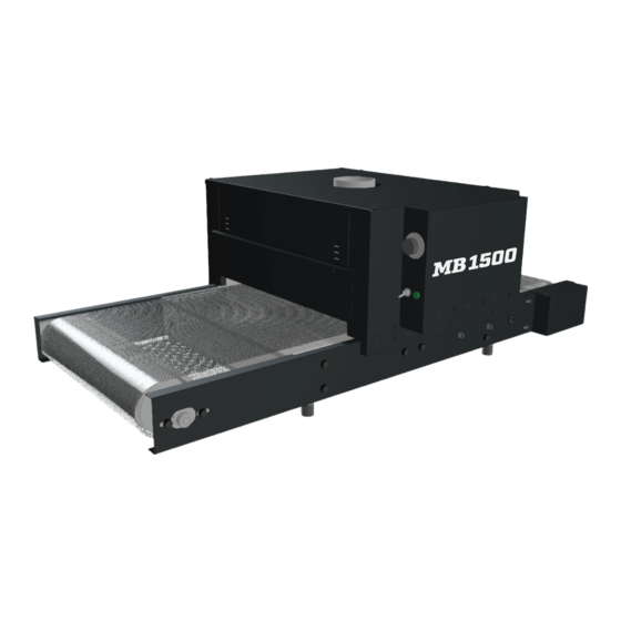
- Page 1 Assembly Instructions INDUSTRIES, INC. MB SERIES TABLE TOP CONVEYOR DRYER...
-
Page 2: Important Instructions
BBC Industries, Inc. is interested in the safe operation of its equipment. All wiring to this equipment must be connected to the electrical source in strict accordance with National Electrical Code (N. E. C.) and local codes having jurisdiction. -
Page 3: Tools Required
TOOLS REQUIRED: • (x1) 1/2” wrench • (x1) 7/16” wrench • (x1) Phillips screwdriver • (x1) Needle nose pliers Power Requirements WATTS VOLTS AMPS FREQUENCY PHASE PLUG 1462 12.18 50/60 HZ NEMA 5-15P /// WARNING /// DO NOT plug the equipment in (or apply power) until instructed to do so. What’s in the box IMAGE DESCRIPTION... -
Page 4: Drive Roller Assembly
IMAGE DESCRIPTION QTY. ITEM # MB21-005 SPLICE CHANNEL 25-025 5/16-18 BOLT MB21-022 TAKEUP ROLLER ASSEMBLY MB21-023 DRIVE ROLLER ASSEMBLY 08-252-MB GEARMOTOR 25-176 #10-32 x 1/2L SCREW 18-119 DRIVE CHAIN AIR-229 CHAIN COVER 25-001 #6-20 x 3/8L SCREW MB21-006 FLOOR PAN 1804-300 CONVERYOR BELT... - Page 5 IMAGE DESCRIPTION QTY. ITEM # 22-057 ROUTING CLIP MB21-014 INNER SIDE PANEL MB21-015 INNER ENTRY/EXIT MB21-018 OUTER SIDE PANEL - CP MB21-025 CONTROL PANEL MB21-017 OUTER SIDE PANEL MB21-020 CHAMBER END CAP MB21-024 HEATER ASSY MB21-016 INNER CHAMBER COVER 22-093 4”...
- Page 6 STEP 1 1. Locate the (4) painted Conveyor Rails (ITEM 1, 2, 3, & 4) from BOX 1 and the (4) rubber Bumper/Feet (ITEM 5) from BOX 2. 2. Thread each Bumper foot into the threaded insert in each of the rails. 3.
- Page 7 STEP 2 Finger Tighten Only Roller Drum Faces Out Sprocket to side with grommet installed TruTrak™ Belt Guide roller drum side out. Locate the Takeup Roller Assy (ITEM 8) in BOX 1. TruTrack™ Belt guide with the guide on the Drive Roller Assy. Note roller drum side out. Tighten the bolts only finger tight.
- Page 8 STEP 3 Sprocket side toward roller Upper oor pan ts between anges ONCE THE CHAIN IS INSTALLED, SLIDE THE MOTOR AWAY FROM ROLLER TO REMOVE SLACK DO NOT REMOVE ALL SLACK INSERT PLUG THEN TIGHTEN SCREWS TO SECURE MOTOR THROUGH HOLE Before tightening screws, slide the motor toward 1/4—1/8 SLACK TOLERANCE...
- Page 9 STEP 4 TruTrak™ Belt guide must be between disks After the pin is re-inserted, slide the (both ends) roller back until the belt is hand tight. Tighten bolts to secure. Loosen bolts and slide after installation of Conveyor Belt Pin ships are installed in one end of the conveyor belt.
- Page 10 STEP 5 Heater Support Rails Flanges Inward to inside of the chamber Flanges Inward 31. Locate the unpainted Inner Chamber sheet metal parts (ITEM 18 & 19) from BOX 2. 19) to one of the Inner Side Panels (ITEM 18). Note the direction of Heater Support Rails and part flanges of the Side Panel per figure.
- Page 11 STEP 6 35. Locate the Outer Side Panel (ITEM 20) in BOX 2. This part is without a label. 36. Locate the Control Panel Assy (ITEM 21) from BOX 3.
- Page 12 STEP 7 38. Install the Control Panel/Side Panel assembled from the previous page to the inner Chamber assembly by sliding it over Inner Side Panel (ITEM 18) from above, the Gearmotor side. 39. Locate the other labeled Outer Side Panel (ITEM 22) from BOX 2. 40.
- Page 13 STEP 8 42. Locate the two Chamber End Caps (ITEM 23) from BOX 2. 43. Rotate the partially assembled chamber onto its end as shown in the figure. 44. Insert one of the End Caps between the two Side Panels with the longest flange to the underside of the chamber.
- Page 14 STEP 9 Insert plug through the grommet and plug into the connector on the control panel Heater anges t over heater support brackets 47. Locate the Heater Assy (ITEM 24) from BOX 3. blocks on the Control Panel side of the Chamber. 49.
- Page 15 STEP 10 Insert the collar into hole bend tabs to secure 52. Locate the Inner Chamber Cover (ITEM 25) from BOX 2. 54. Locate the 4” Duct Start Collar (ITEM 26) from BOX 2. 55. Insert the tabs of the Start collar into the hole in the Inner Chamber Cover and bend up to secure. 56.
- Page 16 STEP 11 58. Locate the two Chamber Curtains (ITEM 28). Mount them on the Entry and Exit of the Heating Chamber at the desired height.
-
Page 17: Controls Overview
CONTROLS OVERVIEW TRAVEL DIRECTION Conveyor Power Switch Conveyor Fuse TRAVEL DIRECTION CONVEYOR SPEED CONTROL HEATER POWER INDICATOR LIGHT HEATER CHAMBER POWER SWITCH FIGURE 13... - Page 18 RECOMMENDED INITIAL START-UP PROCEDURE: 1. Plug the Control Panel into a suitable power source. 2. Turn Belt Speed to 5. Flip the rocker switch for Conveyor Speed to the ON position to start the conveyor. Listen for any unusual noises. Check to see if the rubber edge guide is riding in the roller drum grooves.
-
Page 19: Control Panel Maintenance
F.O.B. factory that may prove defective within 12 months from the date of shipment, which is returned to BBC Industries, Inc. The above warranties are the only warranties made with respect to the equipment. There is no implied...