Table of Contents
Advertisement
Advertisement
Table of Contents

Summary of Contents for Kodak FL5.2
-
Page 3: Table Of Contents
Table of Contents 1. Introduction..........................1 2. Symbols........................... 1 3. Safety............................2 3.1 Handling.........................2 3.2 Installation........................2 3.3 Response to Emergency Situations................. 2 3.4 Warning Labels......................3 4. Product Information....................... 4 4.1 Battery Module Specifications................... 4 4.2 Battery Charge/discharge Curve................5 5. -
Page 4: Introduction
The document describes the installation, commissioning, maintenance and troubleshooting of the following low voltage battery listed below. FL5.2 The battery chemistry of this product is Lithium Iron Phosphate. This manual is designed for qualified personnel only. The tasks described in this document should be performed by authorized and qualified technicians only. -
Page 5: Safety
· Please ensure that all the batteries are grounded properly. · Do not open the battery to repair or disassemble. Only Kodak is allowed to carry out any such · repairs. In case of fire, use only dry powder fire extinguisher. Liquid extinguishers should not be used. -
Page 6: Warning Labels
The battery modules are not water resistant. Hence care should be taken not to get it wet. If you find the battery completely or partially submerged in water do not try to open. Contact authorized personnel or Kodak for further instructions. 3.4 Warning Labels... -
Page 7: Product Information
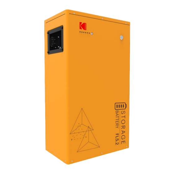
4. Product Information FL5.2 photovoltaic energy storage system is a 48V energy storage system based on lithium-ion ferrous phosphate battery. It is equipped with a customized battery management system (BMS), which is designed for energy storage applications of household photovoltaic power generation users. -
Page 8: Battery Charge/Discharge Curve
4.2 Battery Charge/discharge Curve Current protection Trigger Recover ≥105A, Lasts 30s First level over current ≥60s: Recover Battery charge ≥125A, Lasts 1s ≥60s: Recover Second level over current COC2 First level over current ≥110A, Lasts 300s ≥60s: Recover Second level over current ≥125A, Lasts 30s ≥60s: Recover Battery discharge... -
Page 9: Product Features
5. Product Features 5.1 Battery System Features The batteries have been fitted with multiple protection systems to ensure the safe operation of the system. Some of the protection system includes: Inverter interface protection: Over voltage, over current, external short circuit, reverse polarity, ·... - Page 10 Running LED This LED is used to indicate if the battery is operating effectively. A green light on this LED means the battery is ON and operating normally. Alarm LED This LED is used to indicate if the battery is operating failure. A red light on this LED means the battery is operating abnormally.
-
Page 11: Installation
6. Installation 6.1 Items in the Package Please check if following items are including with the package: Object Quantity Description Object Quantity Description Low voltage battery Communication network cable (0.5m) Bracket Ground wire (0.5m) Expansion tubes & Power line (2m) (Battery to inverter) Expansion screws Network cable (3m) Hexagonal screws... -
Page 12: Clearance
6.2 Clearance Position Min size Left 30cm Right 30cm 30cm Bottom On the ground Make sure to leave a space of at least 30 cm. A clearance of at least 30 cm must be Ieft around the battery pack for proper cooling. Note: Make sure that the battery pack is always exposed to the ambient air. -
Page 13: Installation Steps
6.4 Installation Steps Mounting · STEP-1 Measure and confirm that the bottom of the bracket is 285mm away from the ground, and mark the 5-hole positions on the bracket with a pen. STEP-2 Drill holes with electric drill, make sure the holes are deep enough (at least 50mm) for installation, and then tighten the expansion tubes. - Page 14 STEP A Connect BAT + to POS +, BAT – to NEG – respectively. Connect the battery communication network cable to the lithium battery communication port of the inverter. STEP B Plug the power plug into any output socket on the left or right of the battery. Connect the communication network cable to the CAN interface of the battery, connect the ground terminal of the battery with the ground wire, and lock the nut.
-
Page 15: System Start Up
STEP D Plug the power line of the parallel machine into the remaining output socket of the battery, insert the communication line of the parallel machine into LinkPort0, and lock the ground nut. STEP E Repeat STEP C through STEP D to insert more batteries (up to 8 batteries). 6.5 System Start up When connected to the inverter, turn on the battery first to ensure that the battery voltage output is ·... - Page 16 Number Slave Slave Slave Slave Slave Slave Slave Slave Slave Slave Slave Master batteries 0001 0000 0010 0000 0000 0001 0011 0000 0000 0000 0001 0010 0100 0000 0000 0000 0000 0001 0010 0011 0101 0000 0000 0000 0000 0000 0001 0010 0011...
-
Page 17: Commissioning
7. Commissioning There are seven LED indicators on the front of the battery packs to show its operating status. - Running LED indication After startup, the running indicator light flashes, which indicates that the equipment is in normal operation. - Alarm LED indication When the battery is in normal operation, the alarm LED is off, and after the fault occurs, the alarm LED is always on. - Page 18 Fault status indicated by indicator: ● Off ○ On ◐ Flash Fault List LED1 LED2 LED3 LED4 LED5 ALARM Adc/afe Fault ● ● ● ● ○ ○ ◐ High Voltage Fault ● ● ● ● ○ ○ ◐ Low Voltage Fault ●...
-
Page 19: Exclusion
9.2 Troubleshooting When the red / green LED on the panel is flashing or normally on, it does not mean that the FL5.2 is abnormal, it may be just an alarm or protection. Please check the ‘LED status indicators’ in chapter 7 for the detailed faulty definition before any trouble-shooting steps. - Page 20 V5.1 10-203-00033-06...
