Table of Contents
Troubleshooting

Summary of Contents for TFC AdvantageDC
- Page 1 Product Operation and Maintenance Manual Advantage Detection and Releasing 24 VDC Powered Fire Control Panel Product part no. 830049 Advantage Dual Zone Fire Control Panel Manual part no 650.830049 rev. June 13, 2022...
- Page 2 Product part no. 830049 Advantage Dual Zone Fire Control Panel Manual part no 650.830049 rev. June 13, 2022...
-
Page 3: Table Of Contents
Advantage Dual Zone Fire Control Panel Installation, Operation and Maintenance Instructions Table of Contents - Advantage Dual Zone Control Panel Quick Overview 1.1 AdvantageDC Features Before Using the Advantage Control Panel 2.1 Advantage Control Panel Warnings and Precautions 2.2 Advantage... - Page 4 Appendix and Notes 8.1 Miscellaneous Practical and Technical Notes 8.2 Installation and System Performance Document 8.3 High Temperature Operation 8.4 Spare and Replacement Parts List 8.5 Advantage Product Data Sheet Product Warranty Product part no. 830049 Advantage Dual Zone Fire Control Panel Manual part no 650.830049 rev.
-
Page 5: Advantage Dc Dual Zone Control Panel Quick Overview
Advantage Dual Zone Control Panel Quick Overview The Advantage Dual Detection, Dual Release Zone Control Panel part no. 830049 is the result of years of rugged mining, transit, and military electronic control panel evolution and fire suppression industry design experience. The Advantage control panel’s primary power source is 24 VDC as supplied via a listed industrial power supply. - Page 6 Advantage Part Numbering Scheme Control Panel, FireAway Advantage , Dual Detection/Dual Release, Metal Wiring 830049 Hubs, No Manual Release on Cover Control Panel, FireAway Advantage , Dual Detection/Dual Release, Plastic Wiring 830049-01-01 Hubs, Manual Release Switch on Cover Control Panel, FireAway Advantage , Dual Detection/Dual Release, No Wiring 830049-02-01 Hubs, Manual Release Switch on Cover...
-
Page 7: Advantagedc Features
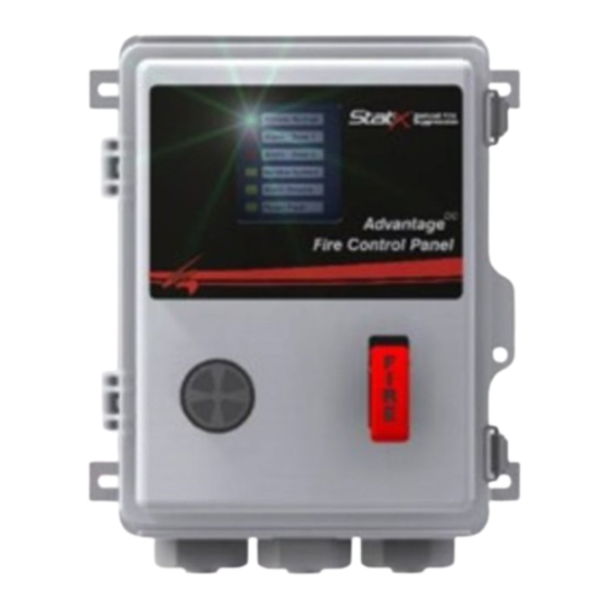
1.1 Advantage Features Control Panel Exterior Features The Advantage enclosure material is made from fiberglass reinforced polycarbonate and is listed as UL508/NEMA Type 4X with an IP-67 Rating and a UL94 V-0 flammability rating. A locking hasp is provided for end-user security purposes. Two types of wiring hubs are available. -
Page 8: Before Using The Advantage
2.0 Before Using the Advantage Control Panel 2.1 Advantage Control Panel Warnings and Precautions Warning! The Advantage Control panel must be installed by a technician familiar with Fire Control panel operation and who has been trained in the operation of the Advantage control panel. -
Page 9: Advantage Dc Control Panel Compliance Notice
2.2 Advantage Control Panel Compliance Notice The Advantage Control Panel is designed per NFPA 17, NFPA 70, NFPA 72 and NFPA 2010 standards for installation, operation, and maintenance. Product Type: Releasing Device Power Limited Circuits: All circuits are power limited Supervised Circuits: Initiating (Detection), Actuation, Auxiliary, Abort Battery Information: This control panel is designed to use a single 9 VDC Nickel Metal Hydride (NiMH) battery as the secondary power source. -
Page 10: Advantage Dc Installation
3.0 Advantage Installation 3.1 Representative Field Wiring Figure 3- Advantage Representative Field Wiring 3.2 Advantage Field Wiring Requirements Pluggable Max Linear Wiring Terminating Terminal Wire Maximum Resistance Cross Resistor Strip Screw Strip Circuit Length (ohms) Section ohms Torque Length 470k 5 in-lbs. -
Page 11: Pluggable Terminal Strip Connections
3.3 Pluggable Terminal Strip Connections Product part no. 830049 Advantage Dual Zone Fire Control Panel Manual part no 650.830049 rev. June 13, 2022... - Page 12 Product part no. 830049 Advantage Dual Zone Fire Control Panel Manual part no 650.830049 rev. June 13, 2022...
-
Page 13: Complete Wiring Connection Table
3.4 Advantage Complete Wiring Connection Table Connector – Pin i.d. Circuit Function Circuit Notes Row A – Top Detection Zone 1 (+) Class B with 470K EOL Detection Zone 1 (-) “ Detection Zone 2 (+) “ Detection Zone 2 (-) “... -
Page 14: Advantage Dc Control Panel Operation
Advantage Control Panel Operation 4.1 Advantage Field Wiring and Control Panel Functions Power Input Circuits Power to the control panel is provided by a 24 VDC output power supply as primary power. A secondary/backup power source is supplied by a 9 vdc rechargeable NiMH battery located inside of the control panel. -
Page 15: Actuation Circuits Operation
Actuation Circuits Operation Two actuation circuits are each capable of actuating up to six Stat-X © aerosol generators or similar devices on each of two separate zones. Power to discharge the actuators is delivered from a bank of super capacitors. Upon Fire detection, the control panel provides a signal to actuate from the fully charged supercapacitor bank. -
Page 16: Local Audible Buzzer Operation
from 0 to 30 seconds via offline PC or SmartDevice programming. Output control contacts control may be mapped to individual detection inputs. Both sets of relay contacts may be programmed for momentary transfer by pressing the front panel Reset Switch. This function may be used for interrupting power to latching function initiating devices (latching relay base smoke detectors). -
Page 17: Internal Clock
Internal Clock A real-time clock is present and should be set when the system is commissioned. The clock is backed up by a supercapacitor, which may lose voltage if the control panel remains unpowered for extended periods beyond a few days. The internal clock may be set via PC or Bluetooth module connection to the circular front panel programming port. -
Page 18: Advantage Default Settings
4.3 Advantage Default Settings The Advantage allows for a variety of programming options as described in section 7. The Advantage default settings for detection, actuation and relay operation are as follows: Advantage Default Configuration Detection Zone Enabled? Actuation Zone Delay Zone 1 Zone 2 Manual Release... -
Page 19: Fault Condition Operation
4.5 Fault Condition Operation If a Fault condition occurs with any of the field wiring or internally supervised circuits, a Fault condition is displayed on one of the front panel LEDs Field wiring circuits include a minimum five second time delay before a Fault condition is annunciated. -
Page 20: Front Panel Switch Operation
4.6 Alarm Test, Alarm Silence, and System Reset Testing The Alarm features of the Advantage may be tested using several methods. 1) Push to Test a) The front panel located Push to Test button can be pressed which will flash all the LEDs ON, sound the audible buzzer but will not transfer I/O relays. - Page 21 Battery Disconnect a. The System Power toggle switch electrically disconnects both the Primary and Secondary power sources. This function disables the Advantage panel and may be used when transporting, shipping, or storing the Advantage control panel for extended periods. b. The Advantage control panel will not operate when the battery disconnect switch is in the System Power –...
- Page 22 4.8 Detection, Actuation & Relay Operation Definitions Cross-Zoned Alarm – Cross-zoning requires one detector on each of two separate zones to be in an Alarm condition before actuation is engaged. A single sensor in alarm causes a Fault condition on the panel. See the following tables for actuation and relay mapping. Mapping –...
- Page 23 The following programming options for detection, actuation and relay mapping may be accessed by offline programming of the Advantage using a PC utility software and interface device or Bluetooth interface module. Refer to Section 7 System Programming for detailed instructions to change the default settings.
- Page 24 Fire Alarm Examples Example 1 – Two detection and releasing zones with single detection and actuation mapping Detection zone 1 goes into alarm due to a linear thermal heat detector fire alarm • o Actuation occurs on zone 1. o The red Fire LED at Alarm Zone 1 is ON o The audible alarm sounds o Relays 1 &...
- Page 25 Example 2 – Two detection zones both cross-zoned detection and actuation using two linear heat detectors with different alarm set points. This example requires two separate detectors in alarm to actuate the system. • Detection zone 1 goes into alarm due to low temperature alarm fire detection o A Fault condition is annunciated at the panel o Relay 1 is programmed as transfer on cross-zoned detection.
-
Page 26: Advantage Dc Maintenance
Advantage Maintenance Periodic maintenance is required for the Advantage control panel. The system test as described in section 4.6 lists the procedure for testing the alarm inputs and control panel functions. Depending upon the local authority having jurisdiction (AHJ), maintenance and testing intervals may vary. - Page 27 Annual Battery Replacement At least annually, the backup battery should be replaced. Dispose of the battery as described in section 2 of this manual and in accordance with local regulations. Disable the Actuators by flipping the Actuation toggle switch to OFF. •...
-
Page 28: Troubleshooting & Customer Support Info
Advantage Troubleshooting and Customer Support Info 6.1 Diagnostic Guide Before performing diagnostics, ensure the system will not discharge accidentally • • Check all connections before replacing components. Look for broken wires, loose or broken connectors and pin/socket connections Look for evidence of corrosion on connectors, pins and sockets •... -
Page 29: Flash Code Troubleshooting Table
6.2 Flash Code Troubleshooting Table Service System Description Troubleshooting Flash Code • Check for continuity on detection zone 1. • Resistance between terminal strip row A position 1 - 2 should read 470K ohms +/- 23.5K ohms Detection Zone 1 •... - Page 30 Fire Alarm Description Troubleshooting Flash Code • Check zone 1 detection wiring circuit for closure. Alarm Zone 1 Check manual release switch circuit for closure. • • Check zone 2 detection wiring circuit for closure. Alarm Zone 2 • Check manual release switch circuit for closure Other LED Description Troubleshooting...
-
Page 31: Advantage
Advantage System Programming Advantage control panel programming options are available via offline PC or SmartDevice Bluetooth interface programming. PC Interface Programming Before enabling the programming mode, ensure the Advantage PC Utility is loaded onto your computer. When installed, the Advantage PC Utility installs a shortcut to your PC desktop. - Page 32 The Advantage programming mode is enabled by pressing and holding the Alarm Silence and System Reset buttons simultaneously for five seconds. An audible alarm will pulse 2X and all LEDs will flash 2X indicating programming mode is enabled. • The Advantage control panel will exit from programming mode and will return to normal operation if no operator action is taken within three minutes Figure 6 - Press System Reset and Alarm Silence to...
- Page 33 Select File and then Set Clock. Select Set System Time which uses the connected PC time and date as the default Advantage clock time. Figure 76- Set Time and Date via the Clock selection Close this window to return to the opening screen. •...
- Page 34 The system Event Log may be viewed by selecting the Event Log menu tab. Once selected, the user can view the Last 20 Events or All Events. Once selected the events will populate the PC screen as follows: Figure 87 - Sample Event Log Setting the system date and time at startup allows for more a more accurate Event Log file.
-
Page 35: Bluetooth Smartdevice Programming
The Monitor Mode function allows the technician to view a snapshot of Advantage operation. Press the Get Status tab for a snapshot view of current control panel status. Both the Event Log and Monitor Mode are useful tools to help in periodic maintenance and troubleshooting. The Monitor Mode function is accessed by selecting the Monitor tab on the start menu. - Page 36 The Advantage App when downloaded to your smartphone will look like this and opens like any other App. Figure 109 - SmartDevice Screenshot Figure 11 - Bluetooth interface plugged into control panel with Bluetooth enabled Once the App is installed, connect the Bluetooth Comm module to the programming port of the Advantage panel.
- Page 37 Enable the App on your Smartdevice. The following screens should appear. Scan to find the Bluetooth interface then select the address of the Bluetooth module to connect with. Once connected, decide which menu to enter. Figure 21 - Front end screen of Figure 22 - Bluetooth device Figure 23 - Menu options for Bluetooth App...
- Page 38 The Configuration tab allows the user to view and change the control panel settings for detection, discharge, FACP operation and Auxiliary Relays. Settings include logical mapping and timing. If a configuration is changed, its good practice to save the configuration to your device and possibly email a copy to be kept as a permanent record.
- Page 39 The Tools menu may be used to set the Advantage panel internal clock and may be used to return any programming settings to their factory default values. The Event Log may be erased as needed but it’s a good practice to save a copy of the log and store the Event Log files using a logical naming convention for easy retrieval and reference.
-
Page 40: Appendix And Notes
Appendix and Notes • 8.1 Miscellaneous Practical and Technical Notes Be sure to bench test the Advantage control panel and all wiring connections • before traveling to the installation site. When storing Advantage batteries, the preferred location is room temperature •... - Page 41 Advantage Installation and System Verification Documentation Installation Property Installation Date Identifier Property Description Phone number Email Address Property Contact Information Installer Name Inspection Date Inspector i.d. Inspection Location Control Panel Serial Date of Last Inspection No/Date Code Primary Battery Secondary Battery Date Code Date Code Advantage...
- Page 42 A - Pre-Inspection System design and installation record available? Control panel green LED ON? Download event log & saved to PC? Detection zone 1 faults? Detection zone 2 faults? Actuation zone 1 faults? Actuation zone 2 faults? Auxiliary input faults? Abort switch fault? Primary battery ault?
- Page 43 C- Sensor, Actuator and Field Wiring Have there been any changes to the installation location which may affect system operation? Is the manual release switch located in the path of egress and unobstructed from access? Is the manual release switch located between 48” and 60” above the floor? Comments: Product part no.
-
Page 44: High Temperature Operation
High Temperature Operation The Advantage utilizes super capacitors and a Nickel Metal Hydride rechargeable battery for high energy actuation. The Advantage can operate intermittently to +85°C (185°F). However extended time above 65°C (150°F) will significantly shorten the control panel’s life. Refer to the chart below for guidance. Figure 12 - Control Panel life vs Operating Temperature Chart Spare and Replacement Parts List The following is a list of spare and replacement parts as described in the Installation,... -
Page 45: Advantage Product Data Sheet
Advantage Product Data Sheet Electrical Specifications Supervised Circuits Visual Indicators Detection (initiating circuits) Qty (2) Class System Normal Green LED (flashing) Manual Pull Station Qty (1) Class Fire Zone 1 & Zone 2 Red LED (flashing) Agent Cylinder Pressure Switch Qty (1) Service System Yellow LED (flashing) - Page 46 Field Wiring Specifications Detection Circuits Manual Release Circuit Maximum length: 100’ each circuit Maximum length: 100’ each circuit Maximum linear resistance: 50 ohms Maximum linear resistance: 50 ohms Conductor cross section: 16-18 AWG Conductor cross section: 16-18 AWG Gold terminal contacts only Gold terminal contacts only IP67 sealed connectors IP67 sealed connectors...
-
Page 47: Product Warranty
9.0 Advantage Product Warranty Seller warrants to Buyer (and to Buyer's customer) that at time of delivery the articles delivered hereunder are free from defects in material and workmanship and conform with the specifications of this order. Seller's sole obligation under this warranty shall be at its option to repair or replace (including payment of shipping charge), or to refund the purchase price of, any article or part thereof which proves to be other than as warranted, and/or to repair the defective component;... - Page 48 Total Fire Systems, inc P.O. Box 1408 Wake Forest, North Carolina 27588 U.S.A Tel: (919) 556-9161 www.tfsnc.com Product part no. 830049-xx-xx AdvantageDC Dual Zone Fire Control Panel Manual part no 650.830049 rev June 13, 2022...