Advertisement
Overview

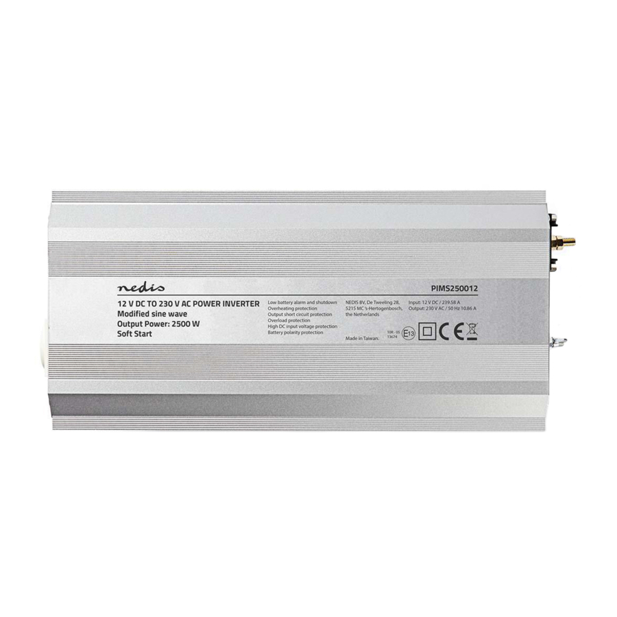
Description
This is a consumer product which complies to EMI test EN 61000-6-4 class A.
This power inverter is a modified sine wave inverter. Modified sine wave inverters are all-purpose power inverters used to power simple electronic devices.

Do not use the inverter with the following rechargeable devices:
- Only mount in a horizontally position.
- Make sure the distance between the battery and inverter is short and only use the provided connection cables.
- This product is an inverter with a modified sinewave output. It is not recommended to connect inductive loads and products with an electro motor inside.
- Small battery-operated appliances which can be plugged directly into the AC output to recharge (e.g. flashlights, razors and nightlights).
- Certain battery chargers for battery packs used in power tools. These battery chargers will have a warning label stating that dangerous voltages are present at the battery terminals.
|
|
|
|
|
|
|
|
|
|
|
|
Terminal
|
|
|
Do not operate the inverter without connecting the inverter to the ground. Risk of electrical shock. The inverter has a lug to connect the chassis with the inverter. The ground wire in the AC junction box on the output panel of the inverter is connected to the chassis. The chassis ground lug must be connected to a grounding point, which will vary depending on where the inverter is installed.
|
|
|
|
|
|
The device can be operated using the remote control. |
Audible alarm
An alarm will sound in case of overtemperature, a low battery or a low-battery shutdown.
Safety
General safety
- Read the manual carefully before use. Keep the manual for future reference.
- The manufacturer is not liable for consequential damages or for damages to property or persons caused by nonobservance of the safety instructions and improper use of the device.
- Only use the device for its intended purposes. Do not use the device for other purposes than described in the manual.
- Do not use the device if any part is damaged or defective. If the device is damaged or defective, replace the device immediately.
- The device is suitable for indoor use only. Do not use the device outdoors.
- The device is suitable for domestic use only. Do not use the device for commercial purposes.
- Only use the device in areas with an ambient temperature between 0°C and 25°C.
- Do not use the device in locations with high humidity, such as bathrooms and swimming pools.
- Do not use the device near bathtubs, showers, basins or other vessels containing water.
- Do not use a timer or a separate remote-control system that switches on the device automatically.
- Do not cover the device.
- Do not block the ventilation openings. Do not insert foreign objects into the ventilation openings.
- Keep a clearance of at least 2,5 cm around the device in order to ensure proper cooling and airflow.
- Place the device on a stable, flat surface.
- Keep the device away from flammable objects.
Electrical safety

- To reduce risk of electric shock, this product should only be opened by an authorized technician when service is required.
- Disconnect the product from the mains socket and other equipment if a problem should occur.
- Read the manual carefully before use. Keep the manual for future reference.
- Only use the device for its intended purposes. Do not use the device for other purposes than described in the manual.
- Do not use the device if any part is damaged or defective. If the device is damaged or defective, replace the device immediately.
Cleaning and maintenance
- Do not use cleaning solvents or abrasives.
- Do not clean the inside of the device.
- Do not attempt to repair the device. If the device does not operate correctly, replace it with a new device.
- Clean the outside of the device using a soft, damp cloth.
- Clean the ventilation openings using a soft brush.
Support
If you need further help or have comments or suggestions please visit www.nedis.com/support
Contact
NEDIS B.V., De Tweeling 28, 5215 MC 's-Hertogenbosch, The Netherlands

Documents / Resources
References
Download manual
Here you can download full pdf version of manual, it may contain additional safety instructions, warranty information, FCC rules, etc.
Advertisement
Thank you! Your question has been received!

Need Assistance?
Do you have a question about the PIMS250012 that isn't answered in the manual? Leave your question here.