Advertisement
Quick Links
-
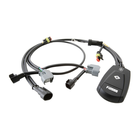
Items Supplied >
1 – Fi2000R-ARB Fuel Injection Module
2 – Zip Ties, (1): 3/32" x 6"; & (1): 3/16" x 8"
1 – Velcro Strip
Instruction Manual >
Read all instructions carefully and completely before installing your new Fi2000R-ARB module.
It is recommended that a qualified mechanic or technician install this product.
Before installing the Fi2000R-ARB it is recommended that the gas tank be low on fuel.
1. Remove the seat; remove the foam cover over the electrics. Unbolt the fuel tank at the back, and
while holding up the rear of the fuel tank about 2", remove the chrome air cleaner housing on the
right side of the engine. Note: Orientation of clamp may need to be reversed 180 degrees, so that
screw head is pointing downward for reassembly later.
2. Temporarily place the Fi200 module on top of the ECU and route the wire harness under the seat
mount on the right hand side and on top of the large wiring harness, (Fig. 1.) Continue by routing
the harness over the top of the right frame rail and along the fuel line and stock harness locations,
(Fig. 2). The Fi2000 connectors should lie close to the stock injector sub harness connector (4
pins).
3. Disconnect the stock injector sub harness connectors (black with 4 pins) by pressing the tab in.
Plug the mating Fi2000 connectors (white with 4 pins) between them, (Fig 2.)
4. Unstrap the stock ECU from it location and move to the side to allow access to the battery post.
Connect the Fi2000's ground lead to the Negative battery post, (Fig. 3.)
5. Before replacing the air cleaner housing, gas tank bolts; seat and ECU to original locations verify
Fi2000 LED Functions.
6. Remove the door from the Fi2000 module to expose the LED's. Verify the wire connections by
(1) turning on the ignition while watching the 3 LED's. They will all light up for a few seconds, and
then go off. This is correct. If you don't see lights, make sure the side stand is up, bike is in
neutral, clutch is in and handle bar engine switch is set to run. If you still have no lights, re-check
that all connectors are fully engaged and the ground wire is connected correctly. (2) After
achieving a steady light from all three LED's, start the motorcycle, the green light should now be
the only LED on. If all three LED's are still on after start up, verify you have attached the injector
connectors correctly. Reattach the access door when finished. Note: Make sure the ignition is
turned off before changing any connection.
* Cobra recommends you always wear a helmet while riding. Please never operate your motorcycle while under
the influence of alcohol and/or drugs. Enjoy the new look of your motorcycle and please ride safely.
DOCUMENT NO. 0017
REV. A
04/08
23801 E. La Palma Ave., Yorba Linda, Ca 92887 Ph. 714.692.8180 Fax. 714.692.5016
Application(s) >
Yamaha Roadstar Warrior
1
92-1772-50
www.fi2000r.com
2002-2009
Page 1 of 3
Advertisement

Related Manuals for Cobra Fi2000


Summary of Contents for Cobra Fi2000
- Page 1 Fi2000 LED Functions. 6. Remove the door from the Fi2000 module to expose the LED’s. Verify the wire connections by (1) turning on the ignition while watching the 3 LED's. They will all light up for a few seconds, and then go off.
- Page 2 7. When everything checks out in order, mount the ECU to the stock location and mount the Fi2000 to the top of the ECU with the supplied Velcro, (FIG 3). Zip tie the Fi2000 harness to the right frame rail and existing harness with the supplied zip ties. Reinstall the air cleaner housing. Make sure the Fi2000 harness is not pinched between frame rail and fuel tank grommet.
- Page 3 FI2000 harness Engine ECU FIGURE 1 Right side Sub-harness frame rail connector (Black with 4 pins) Fi2000 connectors (White with 4 Pins) FIGURE 2 Ground Negative Battery wire Post Engine ECU FIGURE 3 (Engine ECU moved to side for easier access to battery post) DOCUMENT NO.