Advertisement
- 1 Introduction
- 2 Features
- 3 Technical Specifications
- 4 Safety Notes
- 5 ESC Connection diagram
- 6 Soldering the wires
- 7 ESC Installation
- 8 ESC Calibration
- 9 How to calibrate the ESC?
- 10 ESC ON/OFF
- 11 ESC LED indication
- 12 ESC programming
- 13 Profiles Preset
- 14 Trouble Shooting
- 15 Warranty and Service
- 16 Documents / Resources
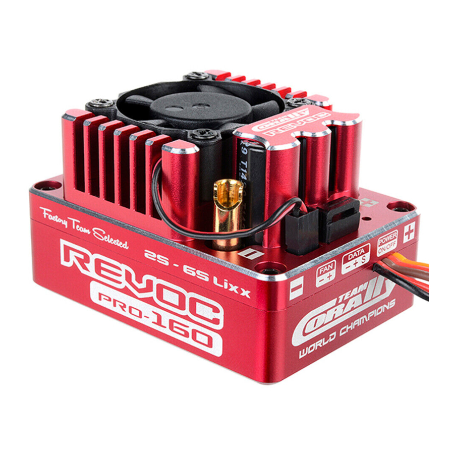
Introduction
The Team Corally REVOC PRO electronic speed controller for sensored and sensorless motors are being fine tuned for the today's high power brushless motors. Everything can be set-up on these controllers to provide you the best functionality and performance.
The REVOC PRO manufactured with the highest grade components to ensure the lowest possible internal resistance re- sulting in a optimized performance. These controllers give the competition racer what he needs. You will experience the best controllability of your RC car, no matter you use it in a on-road or off-road car.
Features
- For sensored and sensorless motors
- Manufactured with the highest grade components
- Ultra compact design
- Aluminium case for improved heat dissipation
- Waterproof power switch
- Advanced boost & turbo timing system for improved acceleration performance
- Enhanced throttle & brake control function.
- 10 programmed profiles can be stored in the ESC
- High power 5A BEC
- Powerful TC Link software to test motor timing and advise the best ESC timing setting
Technical Specifications
| Application | 1/8 Off-Road 1/8 On-Road |
| Cont. Current (A) | 160A |
| Burst (A) | 900A |
| N° of Li-xx Cells | 2 - 6S |
| BEC | 6V - 5A |
| Motor Type | Sensored & Sensorless |
| Motor Limits | 2S - 4S Lipo = < KV 3000 • 4-6 Poles 2S - 6S Lipo = < KV 2200 • 2-4 Poles |
| Resistance | 0.00020 ohm |
| Dimensions | 58x42x36mm |
| Weight | 122g |
Safety Notes
- This ESC is not a toy and only suitable for users from age 14+
- Never allow water, moisture, oil or other materials to get in contact or inside the ESC, motor, or in contact with the PC Boards. It may damage the ESC completely.
- Never disassemble the ESC or modify the components on the PC board
- We strongly suggest to use the original wires and connectors supplied in the ESC packaging
- Never run the ESC without load at full throttle. This may damage the motor bearings and other parts.
- Please select carefully the location of the ESC in your car. Ensure the ESC is mounted in a well ventilated place and with a good airflow so that the heat can dissipate quickly.
- To avoid short circuit, please keep the ESC connectors away from any metal parts.
- Never connect a battery with reversed polarity.
- Please remove the pinion from the motor before you start the calibration and programming of this ESC. Please keep hands, hair, clothes away from the moving gear train.
- Before you start the first testing and calibration of your ESC, make sure all cables and connectors are properly soldered. Keep cables away from all moving parts.
- Select carefully the correct motor timing. The incorrect motor timing will increase the temperature of your ESC and motor. Avoid overloading and overheating at anytime.
- Incorrect Boost and Turbo timing settings may cause permanent damage to the ESC and motor. Please refer to the proper gear ratio and timing settings according to the motor specifications.
- Always switch on the transmitter first and arm then the ESC. To power off, switch off the ESC first and then the transmitter.
- Never use faulty or damaged accessories which may damage the ESC.
- Always insulate exposed wirings with heat shrink tubing or electrical insulation tape to prevent short- circuits. Short-circuits will damage the ESC.
- Always disconnect the battery-pack from the ESC when not in use, to avoid any short-circuits and possible fire hazard. Even when the ESC is switched off, there is still a small cuurent drain and this may cause a complete discharge of the battery after some period of time.
- Never use Ni-xx battery-packs with more then 14 cells or Li-xx battery-packs with more then 6 cells.
Team Corally can never be held responsible for any damage caused or related to the non-compliance with the above instructions.
ESC Connection diagram
- Solder the motor wires to the ESC.
- Phase A from the motor to the A phase connector of the ESC
- Phase B from the motor to the B phase connector of the ESC
- Phase C from the motor to the C phase connector of the ESC
- Solder the battery wires to the ESC
- Red = + (Positive) connector of the ESC
- Black = - (Negative) connector of the ESC
- Connect the motor sensor harness to the ESC. Insert the 6 pin connector into the ESC sensor connector.
- Connect the throttle servo lead to the throttle channel of the Receiver


Soldering the wires
Cut the silicon power wires to the desired length and strip about 3 to 6mm of insulation from the end. Pre-Tin the wire by heating the ends and apply good quality solder until the ends are covered in solder.
Never solder parts to the ESC for more than 5 seconds as some components will come loose or get damaged by the high soldering temperature.
ESC Installation
Choose a location in the car for the ESC where the ESC is most protected from dust and moisture. To prevent radio interference, place the ESC as far as possible away from the receiver and keep all power wires as short as possible. Select also a location that has a good airflow for optimized ventilation. The cooler the ESC remain, the higher the efficiency. Use double sided tape to mount the ESC. Never use glue.
ESC Calibration
The ESC must be calibrated when it is connected for the first time with a new transmitter. The different brands of transmitters have individual signals for full throttle, full brake and neutral position. The calibration of the ESC guarantees the ESC works properly with your transmitter.
How to calibrate the ESC?
- ESC is switched-off
- Connect the ESC to the battery
- Switch-on the transmitter
- Press and hold the ESC on/off switch for a few seconds, the ESC will ring a long beep once. Afterwards the LED will blink RED and the ESC will ring like beep - beep -beep in a row indicating it is ready to set the transmitters input signals for the neutral position, full throttle and full brake step by step. You can release the ESC on/off switch now.
![]()
Keep the throttle trigger of the transmitter in neutral position, press the ESC on/off switch once (1X), the LED will blink GREEN once (1X) and the ESC will ring beep once (1X) which indicates the neutral position is being set and recorded.

![]()
Keep the throttle trigger of the transmitter in full throttle position, press the ESC on/off switch once (1X), the LED will blink GREEN twice (2X) and the ESC will ring beep twice "beep - beep" (2X) which indicates the full throttle position is being set and recorded.

![]()
Keep the throttle trigger of the transmitter in full brake position, press the ESC on/off switch once (1X), the LED will blink GREEN three times (3X) and the ESC will ring beep three times "beep - beep-beep" (3X) which indicates the full brake position is being set and recorded.

- After the calibration is finished, keep the throttle trigger of the transmitter in neutral position, the LED will illuminate RED The ESC and motor is set and ready.
ESC ON/OFF
When the ESC is OFF, press the on/off switch once. The ESC will beep once and the LED will blink RED. When the ESC is on, press and hold the switch for 1 second, the LED will extinguish and the ESC is OFF.

- After running at full load, the ESC can be very hot. In this case, only turn off the ESC after it cooled down.
- When the motor is running, the ESC can not be powered off by pressing the on/off switch. Only when the motor stopped running, the ESC can be powered off. In any emergency, just disconnect the battery power.
- When the motor is running, you can also keep the throttle trigger of the transmitter to full brake position for 8 seconds, the ESC will turn off automatically.
ESC LED indication
| Throttle trigger in NEUTRAL position | Led is BLINKING RED
|
| The motor is running while the throttle trigger is not moved to the highest throttle / brake position | Led is BLINKING GREEN
|
| The motor is running while the throttle trigger is moved to the highest throttle / brake position | Led is continuous illuminated GREEN
|


ESC programming
The ESC can be programmed by the TC Smart Box or by the PC using the TC Wif-Fi module.
Programmable Settings
| Section | Program Item | Description | ||
| Running Mode | Forward / Brake • Forward / Brake / Reverse • Forward / Reverse | |||
| Motor Direction | Normal | Reverse | ||
| ESC Overheat Protection | 85°C / 185°F | 105°C / 221°F | 125°C / 257°F Disable | |
| Motor Overheat Protection | 85°C / 185°F | 105°C / 221°F | 125°C / 257°F Disable | |
| BEC Voltage | 6.0V | |||
| Reverse Speed | 25% - 100% • 1% Increments | |||
| Voltage Cut-Off | 6.0V - 25.0V • 0.1V Increments | Auto Cut-Off • 3.2V Cell | ||
| Throttle Settings | Throttle Input Curve | Linear | Custom | |
| Punch Rate Switch Point | 1% - 99% • 1% Increments | |||
| 1st Stage Punch Rate | 1 - 30 • 1 Increments | |||
| 2nd Stage Punch Rate | 1 - 30 • 1 Increments | |||
| Throttle Dead Band | 0.002 - 0.150ms | |||
| Brake Settings | Brake Input Curve | Linear | Custom | |
| Drag Brake | 0% - 99% • 1% Increments | |||
| Brake Strength | 0% - 99% • 1% Increments | |||
| Initial Brake | = Drag Brake | 0% - 50% • 1% Increments | ||
| Brake Rate Switch Point | 1% - 99% • 1% Increments | |||
| 1st Stage Brake Rate | 1 - 20 • 1 Increments | |||
| 2nd Stage Brake Rate | 1 - 20 • 1 Increments | |||
| Turbo Timing Settings | Turbo Timing | 0 deg° - 15 deg° • 1° Increments | ||
| Turbo Activation Method | Full Throttle | Rpm | Full Throttle + Rpm | |
| Turbo Full Throttle Delay | 0.05 - 1.00 Sec • 0.01 Sec Increments | |||
| Turbo Engage Slope | 1 deg°/0.1S - 64 deg/0.1S° • 1° Increments | |||
If you set the cut-off voltage manually, please note the adjustable voltage is TOTAL cut-off voltage of the battery pack. In AUTO mode, the default cut-off voltage is 3.2V per cell.
- The output power of the motor will be improved when you adjust the motor timing. Electronic motor timing will increase the temperatures of ESC and the motor. Please be carefull when setting up and testing your application to avoid overloading ad overheating. Incorrect Boost and Turbo timing setting may cause permanent damage to the ESC and motors.
- The program items and setting selections vary due to different programming methods.
Profiles Preset
10 Sets of profiles can be programmed and stored in the ESC. The factory default settings are all MODIFY preset which can be used for modified class racing. The racer can pre-program 10 different sets of profiles according to his needs and the data can be called out at any time without any extra special programming.
Profile One (1) Setting Values (Default)
For 1/8 Off-Road, Sensored motor TC Dynotorq 815-4P 2350KV 4S Lipo
| Section | Program Item | Description |
| Running Mode | Forward / Brake | |
| Motor Direction | Normal | |
| ESC Overheat Protection | 105°C / 221°F | |
| Motor Overheat Protection | 105°C / 221°F | |
| Reverse Speed | 25% | |
| Voltage Cut-Off | Auto Cut-Off • 3.2V Cell | |
| Throttle Settings | Throttle Input Curve | Linear |
| Punch Rate Switch Point | 50% | |
| 1st Stage Punch Rate | 3 | |
| 2nd Stage Punch Rate | 3 | |
| Throttle Dead Band | 0.080ms | |
| Throttle Status | ||
| Brake Settings | Brake Input Curve | Linear |
| Drag Brake | 10% | |
| Brake Strength | 75% | |
| Initial Brake | Drag Brake | |
| Brake Rate Switch Point | 50% | |
| 1st Stage Brake Rate | 10 | |
| 2nd Stage Brake Rate | 16 | |
| Turbo Timing Settings | Turbo Timing | 0° |
| Turbo Delay | 0.10 Sec | |
| Turbo Start RPM | 20.000 Rpm | |
| Turbo Engage Slope | 15° / 0.1Sec |
Trouble Shooting
| Problem | Cause | Solution |
| ESC sounds like B-B-B-... | No signal from transmitter | Check the signal wire, connector and trans- mitter |
| ESC sounds like BB-BB-BB-... | Low voltage protection | Change battery |
| ESC sounds like BBB-BBB-BBB-... | ESC overheat protection |
|
| ESC sounds like BBBB-BBBB-BBBB-... | Motor overheat protection |
|
| ESC/Motor protection occurs even the temperature overheat protection is set at 125°C / 257°F | The power system is over- loaded due to over gear ratio, over motor Rpm or over timing settings |
|
Warranty and Service
If material defects or manufacturing faults should arise in a product distributed or manufactured by Team Corally, a division of JSP Group Intl BVBA, and purchased by a consumer, we Team Corally acknowledge the obligation to correct those faults or defects within the limitations described below. This manufacturers warranty is in addition to, and does not affect, the legal or contractual rights of the consumer which arise from the purchase of such products. Team Corally guarantees the consumer that its products are free from material, manufacturing, and construction faults, as determined by the general state of knowledge and technology valid at the time of manufacturing. The fault responsible for causing the damage must be proven to have been present in the product at this time. Claims for compensation arising from consequential damage or product liability will not be considered valid unless they fall under peremptory provisions of the law. If material defects or manufacturing faults should arise in a product distributed or manufactured by Team Corally in the European community (EC) and purchased by a consumer, then Team Corally undertakes to correct those defects within the limitations described below.
This manufacturer's declaration does not affect the consumer's legal or contractual rights regarding defects arising from the purchase contract between the consumer and the dealer or reseller.
Extend of the Warranty If a claim is made under warranty, we take at our discretion to repair or replace the defective goods. We will not consider supplementary claims, especially for reimbursement of costs relating to the defect (e; g. installation / removal costs) and compensation for consequent damages unless they are allowed by statute. This does not affect claims on legal regula- tions, especially according to the product liability law.
Provisions of the Warranty
The purchaser is required to make the warranty claim in writing, and must enclose original proof of purchase (e.g. invoice, receipt, delivery note) and the appropriate warranty card. He must send the defective goods to our local represen- tatives or directly to Team Corally, a division of JSP Group Intl BVBA, Geelseweg 80, 2250 Olen, Belgium at his own risk and cost.
The purchaser should state the material defect or manufacturing fault, or symptoms of the fault, as accurate as possible, so that we can check if our warranty obligation is applicable. The goods are transported from the consumer to us, and from us to the consumer, entirely at the risk and cost of the consumer.
Invalidation of the Warranty
The consumer cannot make a claim under warranty when the fault is affecting the use of the product arising from nat- ural wear, competition use, or improper use (including installation) or external forces. The consumer's adherence to the building and operating instructions relevant to the model, including the installation, operation, use of, and maintenance of, model-related components cannot be supervised by Team Corally. Therefore Team Corally is in no way liable for loss, damage, or costs resulting from improper use, or behavior in any way connected to the above described provisions. Unless otherwise required by law, Team Corally is in no way whatever liable to provide compensation for damages arising from the improper use of the model (including personal injury, death, damage to buildings, loss of turnover, loss of business, or interruption of business, or any other direct, or indirectly caused, consequential damage).
Duration of Validity
The claim period is 24 months from the date of purchase of the product by the consumer from a dealer in the European Community (EC) counted from the date of purchase. The claim period is 12 months from the date of purchase of the product by the consumer from a dealer outside the European Community (EC) counted from the date of purchase. If a defect arises after the end of the claim period, or if evidence or documents required according to this declaration in order to make the claim valid are not presented until after this period, then the consumer forfeits any rights or claims from this declaration. The guarantee period is not prolonged by the granting of any claims within the framework of this warranty, especially in the case of repair or replacement. The guarantee period also does not restart in such cases.
Warranty Expiration
If we do not acknowledge the validity of a claim based on this declaration within the claim period, all claims based on this declaration will expire after six months from the time of registering the claim; however this cannot occur prior to the end of the claim period.
Applicable Law
This declaration, and the claims, rights and obligations arising from it, are based exclusively on the pertinent Belgium Law, without the norms of international private law, and excluding UN retail law. Place of fulfillment for liabilities arising from this declaration is Olen, Belgium. Court of jurisdiction is Turnhout, Belgium.
Copyright
This manual is protected by a copyright. Any publication, transmission or commercial use of this manual is prohibited without written permission. Team Corally and JSP Group Intl BVBA assumes no responsibility for printing errors in this manual. This manual is subject to technical changes.
WEEE:

At the end of this device's useful life, please remove all the batteries and dispose of them separately. Take electrical appliances to the local collection points for waste electrical and elec- tronic equipment. Other components can be disposed of in domestic refuse.
Declaration of Conformity
Team Corally REVOC PRO 160 Controller
Declaration of conformity in accordance with the statutory rules 426/2000 and directive 1999/5/EC (R&TTE)
Team Corally, a division of JSP Group Intl BVBA declares under sole responsibility that the electronic speed controller Revoc 160 Pro with reference nr C-53004 to which this declaration relate, conforms with the following harmonized standards and EU legislations;
EN 60950-1 ed. 2
EN 61000-6-3 ed. 2

Olen - Belgium

12 March 2016 Stefan Engelen Ceo
Team Corally
Geelseweg 80
2250 Olen
Belgium
Tel: +32 14 25 92 94
info@corally.com

Documents / ResourcesDownload manual
Here you can download full pdf version of manual, it may contain additional safety instructions, warranty information, FCC rules, etc.
Advertisement
Thank you! Your question has been received!
Need Assistance?
Do you have a question about the REVOC PRO 160 that isn't answered in the manual? Leave your question here.