
Summary of Contents for Omega GW-001 Series
- Page 1 User’ s Gui d e Shop online omega.com e-mail: info@omega.com For latest product manuals: www.omega.com/en- us/pdf-manuals GW-001 Series Long Range Layer N Ethernet Gateway...
- Page 2 Irlam Manchester M44 5BD Deckenpfronn Germany United Kingdom The information contained in this document is believed to be correct, but OMEGA accepts no liability for any errors it contains and reserves the right to alter specifications without notice. M 5 7 9 0...
-
Page 3: Table Of Contents
Table of Contents Table of Contents..............................3 Notes, Cautions, and Warnings ........................5 Introduction ..............................6 GW-001 Hardware Overview ........................7 Smart Sensor Pairing ............................7 USB 2.0 Connectors ............................7 Serial Data and Alarm Connector ........................7 3.3.1 Alarm Relay Wiring .............................. 7 RJ45 Port ................................. - Page 4 General Public License Statement ......................35 Specifications ............................36 M 5 7 9 0...
-
Page 5: Notes, Cautions, And Warnings
1 Notes, Cautions, and Warnings If the equipment is used in a manner not specified in this manual, the protection by the equipment may be impaired. Do not operate the equipment in flammable or explosive environments. It is important to read and follow all precautions and instructions in this manual before operating or commissioning this device as it contains important information relating to safety and EMC. -
Page 6: Introduction
2 Introduction The Layer N Ethernet Gateway (GW-001 Series) is a high-performance gateway that allows for seamless, wireless, connection to up to 100 long-range Layer N Smart Sensor Devices. The Ethernet-enabled RJ45 connectivity ensures a direct connection to the Layer N Cloud or to a local-area enterprise network. The local built-in web server is also accessible through the RJ45 port. -
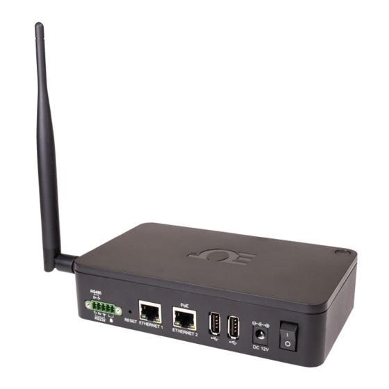
Page 7: Gw-001 Hardware Overview
Pin 4 Alarm (N/O) Pin 5 Alarm (N/O) Contact Omega or visit our website to see other compatible devices. 3.3.1 Alarm Relay Wiring The 5-pin screw terminal can be used to connect a peripheral alarm relay that will be triggered if the gateway loses network connection to the Layer N Cloud or OEG. -
Page 8: Layer N Gateway First-Time Setup
4 Layer N Gateway First-Time Setup Refer to the LED color status table below and follow these instructions to power on the GW-001 unit: LED Color Status Description Amber/Orange (solid) Gateway is powered on; no network connection Green (blinking repeatedly) Gateway is in Pairing Mode or Firmware Upgrade was successful Amber/Orange (blinking + Gateway firmware automatic update... -
Page 9: Registering Your Gateway To Layer N Cloud
Registering your Gateway to Layer N Cloud Note: Users who will not be creating a Layer N Cloud account and will be connecting to Omega Enterprise Gateway (OEG) in a non- internet environment should refer to section 5 First-Time Gateway Internal UI Access To register your Layer N Gateway with Layer N Cloud, you must first create and register a Layer N Cloud account. -
Page 10: First-Time Gateway Internal Ui Access
Static IP under the Network Settings menu. Additionally, after the first-time setup, the user may choose to enable Enterprise Mode to pair the GW-001 to an Omega Enterprise Gateway (OEG) account. Refer to the section titled 6 Registering your Gateway to OEG (Enterprise Mode) to learn more about how to enable Enterprise Mode and to pair a GW-001 to OEG, or continue below for an explanation of the different menus available in the GW-001 internal UI. -
Page 11: Controller
Figure 9: Add Device – Controller Setup 5.1.1.1 Omega Platinum Omega Platinum controllers being added to the GW-001 require users to identify the IP address and Port number of the Controller device. Figure 10: Platinum series controller Add Device interface... -
Page 12: Daq
ID, and reading interval. Figure 11: DAQ series Add Device interface Omega DAQ devices require users to know the IP address of their controller device. An IP scanner software can be used to identify the DAQ IP address. 5.1.3... -
Page 13: Probe
5.1.4 Probe To add a Smart Probe, select it from the Product Family dropdown and select your Product Model from the dropdown. You can then set the communication parameters for your device including the interface type, device ID, and reading interval. -
Page 14: Gw-001 Settings
GW-001 Settings Click the settings tab to view log data, update gateway firmware versions, change security passwords, and view current network settings. 5.2.1 Network Settings To view and change the Network settings, select it from the Settings dropdown at the top right of the webpage UI. -
Page 15: System Settings
5.2.3 System Settings To update your gateway firmware version, factory reset your device, or soft reboot your device, select System from the Settings dropdown at the top right of the webpage UI. When updating the firmware version, click Check Online to download the latest firmware version available for your gateway. -
Page 16: Registering Your Gateway To Oeg (Enterprise Mode)
6 Registering your Gateway to OEG (Enterprise Mode) A Layer N Gateway can be added to Omega Enterprise Gateway (OEG) in a non-internet environment by enabling Enterprise Mode on the Gateway unit. To add a Layer N Gateway to OEG, the Cloud Registration option needs to be disabled by accessing the System Settings in the Gateway web UI. - Page 17 Step 5: Click the icon or Add Devices. Then select Layer N from the Product Family dropdown and GW-XXX-X from the Product Model dropdown. Figure 19: OEG interface Add Device menu – Layer N GW-XXX-X Step 6: Input the IP Address of the connected Layer N Gateway as it appears in your local-area network. Figure 20: OEG interface Add Device menu –...
-
Page 18: Configuring Sensing Devices After Pairing With Oeg
The maximum reading interval is 120 seconds for Layer N Gateway. After switching to Enterprise Mode from Cloud Mode, the Layer N Gateway device should be manually powered off and on again. Omega Enterprise Gateway should also be restarted from the Windows OS Services application. In the future, if users will be using the Layer N Cloud service, they must navigate to the Gateway web UI again to uncheck the Turn off Cloud Registration box. -
Page 19: How To Pair A Sensing Device To A Layer N Gateway
7 How to Pair a Sensing Device to a Layer N Gateway Refer to either the Wireless Pairing or Wired Pairing instructions as applicable. Wireless Pairing Pairing your wireless Smart Interface (IF-006) or Smart Sensor is made easy with a one-button pairing system between the IF-006 or Smart Sensor and the Layer N Gateway. -
Page 20: Wired Pairing
Wired Pairing Wired Smart Probes connected directly to a Layer N Gateway with an IF-001 cable will need to add the device to the Gateway Internal User Interface. The Connected Devices tab is the default page set once you are signed in to the internal gateway UI. From here, you can add devices to your gateway to have them appear in your Layer N Cloud account. -
Page 21: Navigating Layer N Cloud
The Layer N Cloud delivers state and status monitoring, data logging, visualization, and analytics. Accounts can be created and accessed by visiting: http://cloud.omega.com Once you have access to your account and have completed your initial device pairing, you will be presented with your connected devices on the Layer N Cloud interface. -
Page 22: Management
8.1.2 Management Clicking the management icon allows you to create customizable groups of gateways, assign gateways to admins, and assign alarm notifications to other users. 8.1.2.1 User and Device Assignment To assign users to devices, click the Groups icon, and click Add Group. - Page 23 Step 3: Once your group is created, a pop-up window will appear with the title Manage Device Groups. Click icon to add a user’s email address and grant them access to the group. Click OK to finalize the changes. Note: Before adding a user to a group, the user must be granted access to the Layer N Cloud account by completing the steps outlined in section 2.2.2 How to Add Users.
-
Page 24: Sensor Analytics
8.1.3 Sensor Analytics To access the analytics of a specific sensor, click on the measurements of the sensor you wish to view. 8.1.3.1 Measurements The measurements tab displays graphs of the readings recorded by your sensor. It allows users to change between live readings and specified ranges of time. - Page 25 To solve the alarm chattering issue, Omega has implemented a Deadband feature into the Layer N Cloud. Also known as hysteresis, the deadband establishes a range, or threshold, of values from the setpoint that the Layer N Cloud will accept before the alarm is triggered.
- Page 26 In the Layer N Cloud, the deadband feature in the alarm settings is expressed as a percentage. For example, if a user enters a value of 5 in the deadband text box, a range of +5% to -5% from the threshold has been established and the alarm will not be triggered within that region.
-
Page 27: Historian
Historian The Historian tab allows users to create reports of past readings within a range of time and presents them as a graph. Through the Historian tab, users can export their chart data as a .csv file. Begin by clicking Select Devices and making your selection. - Page 28 Figure 39: Historical Data Report parameters Users can then select the desired device(s) to add to the report by clicking the associated checkboxes. Click OK to finalize the selection. Figure 40: Historical Data Report Select Devices interface Select a period or a range of dates To specify the range of time the report will cover, users can select Today, This Week, or Custom date and time.
- Page 29 Graph Data Presentation The Historian interface provides three methods of presenting graphed data: Plot Time Series, Plot Histogram, and Plot Prediction. Figure 42: Graph data viewing options Plot Time Series Figure 43: Plot time series graph view Plot Histogram Figure 44: Plot Histogram graph view 29 | M 5 7 9 0...
- Page 30 Plot Prediction To utilize the Plot Prediction feature, enter the date and time of the value you would like to predict and click the Predict Future Values button to display the data. Figure 45: Plot Prediction graph view 30 | M 5 7 9 0...
-
Page 31: System Settings
System Settings The System settings for the Layer N Cloud allow you to customize your profile information, the units of measure displayed, user access permission, subscription management, and includes contact information for technical support and feedback. Profile 8.3.1 The Profile tab allows users to configure settings such as associated email addresses, passwords, security questions, and notifications. -
Page 32: Units
8.3.2 Units The units tab allows users to set their preferred units of measure as they appear on the Layer N Cloud. Changing the units here does not change the units of your sensing devices. It only changes the unit of measure as it appears on the Layer N Cloud. -
Page 33: Subscription
8.3.4 Subscription The Subscription tab shows your current subscription tier and provides a link to the Omega website should you choose to upgrade your subscription plan. If you purchased the subscription with a billing email different than your Layer N Cloud account email, you may link the two here. -
Page 34: How To Remove A Paired Smart Sensor From A Gateway
How to Remove a Paired Smart Sensor from a Gateway To remove a paired Smart Sensor (such as the SS-001) from a Gateway, follow the steps below: Step 1: Log in to the Layer N Cloud account associated with the paired devices. -
Page 35: Certification
LGPL. If you have any questions or wish to receive a copy of any source code that you may be entitled under the term, please contact us at: iiot-opensource@omega.com Please include the SKU of this product in your request. - Page 36 General Max number of Smart Sensors: Up to 40 Smart Sensors can connect to the Gateway unit. All specifications are subject to changes without prior notifications. Please visit Omega.com for the latest information. 36 | M 5 7 9 0...
- Page 37 Department will issue an Authorized Return (AR) number immediately upon phone or written request. Upon examination by OMEGA, if the unit is found to be defective, it will be repaired or replaced at no charge. OMEGA’s WARRANTY does not apply to defects resulting from any action of the purchaser, including but not limited to mishandling, improper interfacing, operation outside of design limits, improper repair, or unauthorized modification.
- Page 38 Where Do I Find Everything I Need for Process Measurement and Control? OMEGA…Of Course! Shop online at omega.com TEMPERATURE M U Thermocouple, RTD & Thermistor Probes, Connectors, Panels & Assemblies M U Wire: Thermocouple, RTD & Thermistor M U Calibrators & Ice Point References M U Recorders, Controllers &...