Boss Ladderspan 3T Instruction Manual
Mobile aluminium tower
Hide thumbs
Also See for Ladderspan 3T:
- Instruction manual (24 pages) ,
- User manual (32 pages) ,
- Instruction manual (28 pages)

Related Manuals for Boss Ladderspan 3T


Summary of Contents for Boss Ladderspan 3T
- Page 1 Ladderspan Mobile Aluminium Tower 1450/850 Ladderspan 3T - Through the Trapdoor Method Instruction Manual EN 1004-2 en...
- Page 2 BoSS Ladderspan 3T Instruction Manual...
-
Page 3: Table Of Contents
Contents Safety First Introduction Tower Designation Maintenance - Storage - Transport Building the Tower Pre-Assembly Checks Component Diagram Quantity Schedule Stabilisers Assembly 2.5.1 Assembly General: Steps 2.5.2 Assembly For 1450 Towers: Steps 2.5.3 Assembly For 850 Towers: Steps Dismantling Using the Tower Safety Checklist Pre-Use Checklist Movement Of The Assembled Prefabricated Tower Scaffold... -
Page 4: Safety First
User training courses are available, but must not be used as a substitute for familiarity with this manual. BoSS mobile aluminium towers are light-weight scaffold towers used throughout the building and construction industry for both indoor and outdoor access solutions where a stable and secure platform is required. -
Page 5: Tower Designation
Clear Height Class (H1 = 1.85m, H2 = 1.90m) *UDL = Uniformly distributed load Maintenance - Storage – Transport • The BoSS mobile tower system is robust and requires little maintenance. • All components and their parts should be regularly inspected to identify damage, particularly to joints. -
Page 6: Building The Tower
• Check the surface is level within the 210mm range of the adjustable legs. • Only components specified in this manual shall be used with BoSS towers. Check all required components are onsite and in a suitable working condition. •... - Page 7 Building The Tower • Check this manual is available and its contents familiar to all those involved. • If assembling outdoors; check the forecast windspeed. ○ The assembled tower is certified to wind forces equating to 27mph, but handling components under those conditions would be hazardous.
-
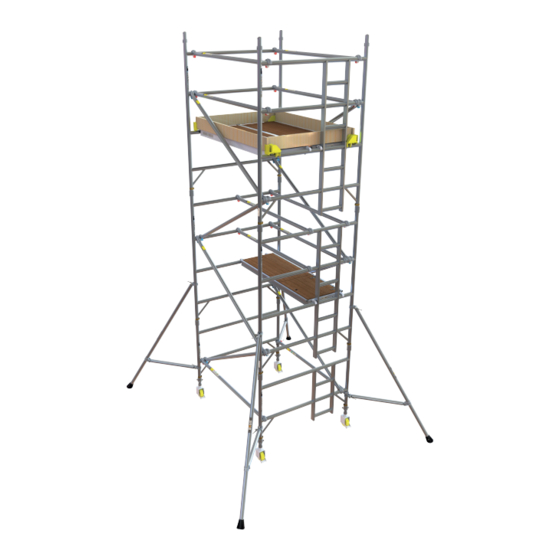
Page 8: Component Diagram
Brace Ladder Frame 4 Rung Span End Toe Frame Board 4 Rung Side Board Platform (Fixed and Trapdoor Platforms) Diagonal Brace Stabiliser Span Frame 2 Rung Adjustable Leg Instruction Ladder Frame Castor Manual 2 Rung BoSS Ladderspan 3T Instruction Manual... - Page 9 Building The Tower Component Weights Component Code Name Weight (kgs) 32842300 Castor 150mm 33551300 Adjustable Leg 60851300 Ladder Frame 850 2 Rung 60251300 Span Frame 850 2 Rung 60751300 Ladder Frame 850 3 Rung 60151300 Span Frame 850 3 Rung 60651300 Ladder Frame 850 4 Rung 60051300...
-
Page 10: Assembly For 1450 Towers: Steps 4 To
Building The Tower BoSS Ladderspan 3T Instruction Manual... -
Page 11: Assembly For 850 Towers: Steps 4 To
Building The Tower bossaccesstowers.com... -
Page 12: Quantity Schedule
High clearance frames must not be used in conjunction with walk-through frames. Component Weight Description Code (kg) High Clearance Frame 30051500 10.0 1.8m High Clearance Frame 30151500 12.0 2.5m BoSS Ladderspan 3T Instruction Manual... -
Page 13: Stabilisers
Building The Tower Walk-through Frame If side walk-through access is required at the base of 4.2m, 6.2m, 8.2m, 10.2m or 12.2m platform height towers, high clearance frames may be used in place of the four lower diagonal braces and two lower horizontal braces. -
Page 14: Assembly
Ensure when the base is levelled the distance from the ground to the first climbing rung is less than 400mm. • Stabilisers of the size specified in the quantity schedule should be fitted at the earliest opportunity. BoSS Ladderspan 3T Instruction Manual... - Page 15 Building The Tower • Always start assembly with the smallest end frames at the base. Platform Height (m) Frame at Base 1.7, 2.2, 3.7, 4.2, 5.7, 6.2, 7.7, 9.7, 10.2, 11.7,12.2 2 Rung 2.7, 4.7, 6.7, 8.7, 10.7 3 Rung 1.2, 3.2, 5.2, 7.2, 9.2, 11.2 4 Rung •...
- Page 16 Fit a second horizontal brace between the bottom rungs on the other side of the frames to square the tower. Assembly for 1450 towers, see page 15 for following steps. Assembly for 850 towers, see page 18 for following steps. BoSS Ladderspan 3T Instruction Manual...
- Page 17 Building The Tower 2.5.2 Assembly For 1450 Towers The procedure illustrated shows a 4.2m platform height tower starting with a 2 rung end frame. Fit two additional end frames, ensuring the frame interlock clips are engaged. Fit two diagonal braces (blue) in opposite directions between the 1 and 3 rungs.
- Page 18 (as shown in Step 5). At the required platform height, fit the fixed platform and a trapdoor platform alongside it. Fit the final guardrails (as shown in Step 5). BoSS Ladderspan 3T Instruction Manual...
- Page 19 Building the Tower Fit toe boards. The tower is now complete. bossaccesstowers.com...
- Page 20 Fit stabilisers (see notes on page 11). Fit the next pair of end frames and check the frame interlock clips are engaged. INTERLOCK CLIP Unlocked Locked BoSS Ladderspan 3T Instruction Manual...
- Page 21 Building The Tower Fit two pairs of diagonal braces in opposite directions between the 3 and 5 rungs and the 5 and 7 rungs. Locate a trapdoor platform on the 6 rung, with the trapdoor next to the ladder. Climb up the inside of the tower and from protected position of the trapdoor, fit guardrails to the 7 and 8...
-
Page 22: Dismantling
When removing the guardrails unlock the four claws furthest from the trapdoor and return immediately to the protected position within the trapdoor. The other claws can then be unlocked, and the guardrails removed from the tower. BoSS Ladderspan 3T Instruction Manual... -
Page 23: Using The Tower
Using The Tower Safety Checklist This inspection must be carried out before initial use, after moving the tower, if any environmental condition change that may affect the tower and at regular intervals determined by local regulations. Local regulations may also specify other information to be supplied to the user or attached to the structure. -
Page 24: Use
The adjustable legs are for levelling the tower only. They must not be used to gain extra height. • Do not use boxes, stepladders or other objects to gain extra height. • Beware of horizontal forces that might cause instability. Maximum horizontal force = 30kg. BoSS Ladderspan 3T Instruction Manual... - Page 25 Using The Tower • Beware of high winds. This tower has been assessed as a freestanding structure for wind loads equating to 27mph (43kph, 12m/s). If greater windspeeds are forecast the tower must be moved to a sheltered location or dismantled while it is still safe to do so. •...
-
Page 26: Movement Of The Assembled Prefabricated Tower Scaffold
Ensure there are no persons, tools, or materials on the tower. • Release the castor brakes. • Release the stabiliser top clamp to allow the feet to be raised a maximum of 25mm. Re-tighten the clamps. BoSS Ladderspan 3T Instruction Manual... - Page 27 Using The Tower During • The tower must be moved only by manual effort, pushing at the base of the tower. • Constant attention must be given to the position of the castors, stabiliser feet and the top of the tower. •...
- Page 28 For further information and support for the Ladderspan or any other products, design advice and services, please contact: Werner UK Sales & Distribution Ltd. Blackwater Trading Estate, The Causeway, Maldon, Essex, CM9 4LJ, United Kingdom WernerCo Hungary Kft. 6000 Kecskemét, Szt.