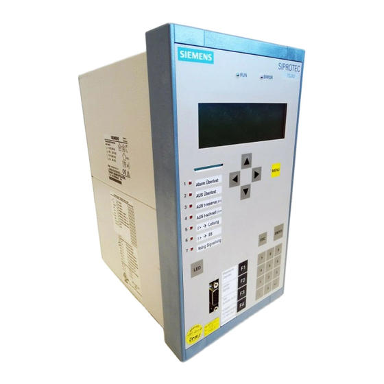
Siemens SIPROTEC 7SJ61 Manual
Multi-functional protective relay with bay controller
Hide thumbs
Also See for SIPROTEC 7SJ61:
- Technical data manual (58 pages) ,
- Manual (94 pages) ,
- Manual (72 pages)
Table of Contents

Related Manuals for Siemens SIPROTEC 7SJ61


Summary of Contents for Siemens SIPROTEC 7SJ61
- Page 1 Preface Contents Introduction SIPROTEC Functions Multi-functional Protective Mounting and Commissioning Relay with Bay Controller Technical Data 7SJ61 Appendix V4.7 Literature Manual Glossary Index C53000-G1140-C210-1...
- Page 2 SIPROTEC, SINAUT, SICAM and DIGSI are registered trademarks Document version V04.00.02 of Siemens AG. Other designations in this manual might be trade- marks whose use by third parties for their own purposes would in- Release date 02.2008 fringe the rights of the owner.
- Page 3 Council Directive 89/336/EEC) and concerning electrical equipment for use within specified voltage limits (Low-voltage Directive 73/23 EEC). This conformity has been established by means of tests conducted by Siemens AG in accor- dance with Article 10 of the Council Directive in agreement with the generic standards EN 61000-6-2 and EN 61000-6-4 for the EMC directive, and with the standard EN 60255-6 for the low-voltage directive.
- Page 4 Additional Support Should further information on the System SIPROTEC 4 be desired or should particular problems arise which are not covered sufficiently for the purchaser's purpose, the matter should be referred to the local Siemens rep- resentative. Our Customer Support Center provides a 24-hour service.
- Page 5 Preface Safety Information This manual does not constitute a complete index of all required safety measures for operation of the equip- ment (module, device), as special operational conditions may require additional measures. However, it com- prises important information that should be noted for purposes of personal safety as well as avoiding material damage.
- Page 6 The operational equipment (device, module) may only be used for such applications as set out in the catalogue and the technical description, and only in combination with third-party equipment recommended or approved by Siemens. The successful and safe operation of the device is dependent on proper handling, storage, installation, opera- tion, and maintenance.
- Page 7 Preface Typographic and Symbol Conventions The following text formats are used when literal information from the device or to the device appear in the text flow: Parameter Names Designators of configuration or function parameters which may appear word-for-word in the display of the device or on the screen of a personal computer (with operation software DIGSI), are marked in bold letters in monospace type style.
- Page 8 Preface Besides these, graphical symbols are used in accordance with IEC 60617-12 and IEC 60617-13 or similar. Some of the most frequently used are listed below: Input signal of analog quantity AND-gate operation of input values OR-gate operation of input values Exklusive OR-gate (antivalence): output is active, if only one of the inputs is active Coincidence gate (equivalence): output is active, if both inputs are...
-
Page 9: Table Of Contents
Contents Introduction................17 Overall Operation. - Page 10 Contents Overcurrent Protection 50, 51, 50N, 51N ..........48 2.2.1 General .
- Page 11 Contents Thermal Overload Protection 49 ........... . .124 2.7.1 Description .
- Page 12 Contents 2.13 Flexible Protection Functions ............191 2.13.1 Function Description .
- Page 13 Contents 2.17 Auxiliary Functions..............213 2.17.1 Message Processing .
- Page 14 Contents 2.18 Breaker Control ..............244 2.18.1 Control Device.
- Page 15 Contents Technical Data................305 General Device Data .
- Page 16 Contents Terminal Assignments ............. 376 A.2.1 Housing for Panel Flush and Cubicle Mounting .
-
Page 17: Introduction
Introduction The SIPROTEC 7SJ61 device is introduced in this chapter. An overview of the 7SJ61 is presented with its ap- plications areas, characteristics, and scope of functions. Overall Operation Application Scope Characteristics SIPROTEC, 7SJ61, Manual C53000-G1140-C210-1, Release date 02.2008... -
Page 18: Overall Operation
1.1 Overall Operation Overall Operation The numerical, multi-functional protection device SIPROTEC 7SJ61 is equipped with a powerful microproces- sor. It allows all tasks to be processed digitally, from the acquisition of measured quantities to sending com- mands to circuit breakers. Figure 1-1 shows the basic structure of the device. - Page 19 Introduction 1.1 Overall Operation Microcomputer System Apart from processing the measured values, the microcomputer system (µC) also executes the actual protec- tion and control functions. They especially include: • Filtering and preparation of the measured quantities • Continuous monitoring of the measured quantities •...
- Page 20 Introduction 1.1 Overall Operation Serial Interfaces The Front PC Interface is provided for local communications with a personal computer using the DIGSI soft- ware. This facilitates a comfortable handling of all device functions. The Rear Service Interface can also be used to communicate with the relay from a PC running the DIGSI soft- ware.
-
Page 21: Application Scope
Introduction 1.2 Application Scope Application Scope The numerical, multi-functional SIPROTEC 4 7SJ61 is a versatile device designed for protection, control and monitoring of busbar feeders. For line protection, the device can be used in networks with earthed, low resis- tance earthed, isolated or compensated neutral point. It is suited for networks that are radial and supplied from a single source or open looped networks. - Page 22 Introduction 1.2 Application Scope Messages and Measured Values; Recording of Event and Fault Data The operational indications provide information about conditions in the power system and the device. Measure- ment quantities and values that are calculated can be displayed locally and communicated via the serial inter- faces.
-
Page 23: Characteristics
Introduction 1.3 Characteristics Characteristics General Characteristics • Powerful 32-bit microprocessor system. • Complete digital processing and control of measured values, from the sampling of the analog input quanti- ties to the initiation of outputs, for example, tripping or closing circuit breakers or other switchgear devices. •... - Page 24 Introduction 1.3 Characteristics Ground Fault Protection 50N, 51N • Three definite time overcurrent protective elements and one inverse time overcurrent protective element for high-resistance ground faults in grounded systems; • Different curves of common standards are available for 51 and 51N, or a user-defined characteristic; •...
- Page 25 Introduction 1.3 Characteristics Thermal Overload Protection 49 • Thermal profile of energy losses (overload protection has total memory capability); • True r.m.s. calculation; • Adjustable thermal alarm level; • Adjustable alarm level based on current magnitude; • Additional time constant setting for motors to accommodate the motor at standstill; •...
- Page 26 Introduction 1.3 Characteristics Flexible Protective Functions • Up to 20 protection functions which can be set individually to operate in three-phase or single-phase mode; • Any calculated or directly measured value can be evaluated on principle; • Standard protection logic function with definite time characteristic; •...
-
Page 27: Functions
Functions This chapter describes the numerous functions available on the SIPROTEC 4 device 7SJ61. It shows the setting possibilities for each function in maximum configuration. Information with regard to the determination of setting values as well as formulas, if required, are also provided. Based on the following information, it can also be determined which of the provided functions should be used. -
Page 28: General
Functions 2.1 General General The settings associated with the various device functions may be modified using the operating or service inter- face in DIGSI in conjunction with a personal computer. Some parameters may also be changed using the con- trols on the front panel of the device. The procedure is set out in detail in the SIPROTEC System Description /1/. 2.1.1 Functions Overview The 7SJ61 relay contains protection functions as well as many other functions. -
Page 29: Setting Notes
Functions 2.1 General 2.1.1.2 Setting Notes Setting the Functional Scope Configuration settings can be entered using a PC and the software program DIGSI and transferred via the front serial port or the rear service interface of the device. The operation via DIGSI is explained in the SIPROTEC 4 System Description. -
Page 30: Settings
Functions 2.1 General When using trip circuit supervision, address 182 74 Trip Ct Supv allows you to select whether this function should work with two (2 Binary Inputs) or only one binary input (1 Binary Input) or if the function is Disabled. - Page 31 Functions 2.1 General Addr. Parameter Setting Options Default Setting Comments Disabled Disabled 46 Negative Sequence Protection TOC ANSI TOC IEC Definite Time Disabled Disabled 48 Startup Supervision of Motors Enabled Disabled Disabled 49 Thermal Overload Protection No ambient temp With amb. temp. 66 #of Starts Disabled Disabled...
-
Page 32: Device, General Settings
Functions 2.1 General 2.1.2 Device, General Settings The device requires some general information. This may be, for example, the type of annunciation to be issued in the event of a power system fault occurs. 2.1.2.1 Description Command-dependent Messages "No Trip – No Flag" The indication of messages masked to local LEDs and the provision of spontaneous messages can be made dependent on whether the device has issued a trip signal. -
Page 33: Settings
Functions 2.1 General 2.1.2.3 Settings Addr. Parameter Setting Options Default Setting Comments FltDisp.LED/LCD Target on PU Target on PU Fault Display on LED / LCD Target on TRIP Start image DD image 1 image 1 Start image Default Display image 2 image 3 image 4 2.1.2.4 Information List... - Page 34 Functions 2.1 General Information Type of In- Comments formation Error 0V Error 0V Error -5V Error -5V Error PwrSupply Error Power Supply Alarm Sum Event Alarm Summary Event Fail Battery Failure: Battery empty I/O-Board error I/O-Board Error Error A/D-conv. Error: A/D converter Error Board 1 Error Board 1 Error Board 2...
-
Page 35: Power System Data 1
Functions 2.1 General 2.1.3 Power System Data 1 2.1.3.1 Description The device requires certain basic data regarding the protected equipment, so that the device can adapt to its desired application. These may be, for instance, nominal power system and transformer data, measured quan- tity polarities and their physical connections, breaker properties (where applicable) etc. - Page 36 Functions 2.1 General Polarity of Current Transformers (Power System) At address 201 CT Starpoint, the polarity of the wye-connected current transformers is specified (the fol- lowing figure applies accordingly to two current transformers). This setting determines the measuring direction of the device (forward = line direction). Changing this parameter also results in a polarity reversal of the ground current inputs I or I Figure 2-2...
- Page 37 Functions 2.1 General Figure 2-3 Measurement of two ground currents, example The phase currents I and I must be connected to the first current input (terminals Q1, Q2) and to the third (terminals Q5, Q6). At the fourth input (terminals Q7, Q8) the ground current I or I is connected as usual, in this case the ground current of the line.
- Page 38 Functions 2.1 General The assignment of the protection functions to the ground current inputs in special connections is set out in the following table. Current Input function Time Overcurrent Protection Ground (Chapter 2.2) or I Ground Fault Detection (sensitive / neutral - Chapter 2.9) N sensitive Single-phase Time Overcurrent Protection (Chapter 2.4) Intermittent Ground Fault Protection (Chapter 2.10)
- Page 39 Functions 2.1 General Current Flow Monitoring (Breaker) Address 212 BkrClosed I MIN corresponds to the threshold value of the integrated current flow monitoring system. This parameter is used by several protection functions (e.g. overload protection and auto-reclosure for motors). If the set threshold current is exceeded, the circuit breaker is considered closed and the power system is considered to be in operation.
-
Page 40: Settings
Functions 2.1 General 2.1.3.3 Settings Addresses which have an appended "A" can only be changed with DIGSI, under "Display Additional Settings". The table indicates region-specific default settings. Column C (configuration) indicates the corresponding sec- ondary nominal current of the current transformer. Addr. -
Page 41: Information List
Functions 2.1 General Addr. Parameter Setting Options Default Setting Comments T 52 BREAKTIME 1 .. 600 ms 80 ms Breaktime (52 Breaker) T 52 OPENING 1 .. 500 ms 65 ms Opening Time (52 Break- TEMP. UNIT Celsius Celsius Unit of temperature mea- Fahrenheit surement Holmgr. -
Page 42: Setting Notes
Functions 2.1 General Note The signals used for binary tracks can be configured in DIGSI. Note If via parameter 251 CT Connect. one of the current transformer connection types A,G2,C,G; G->B or A,G2,C,G; G2->B has been selected, the measured ground current I measured by the second current transformer is indicated under track „iN“. -
Page 43: Settings
Functions 2.1 General 2.1.4.3 Settings Addr. Parameter Setting Options Default Setting Comments WAVEFORMTRIGGE Save w. Pickup Save w. Pickup Waveform Capture Save w. TRIP Start w. TRIP WAVEFORM DATA Fault event Fault event Scope of Waveform Data Pow.Sys.Flt. MAX. LENGTH 0.30 .. -
Page 44: Setting Notes
Functions 2.1 General 2.1.5.2 Setting Notes General If setting group change option is not required, Group A is the default selection. Then, the rest of this section is not applicable. If the changeover option is desired, group changeover must be set to Grp Chge OPTION = Enabled (address 103) when the function extent is configured. -
Page 45: Power System Data 2
Functions 2.1 General 2.1.6 Power System Data 2 2.1.6.1 Description The general protection data (P.System Data 2) includes settings associated with all functions rather than a specific protection or monitoring function. In contrast to the P.System Data 1 as discussed before, they can be changed over with the setting groups. -
Page 46: Settings
Functions 2.1 General 2.1.6.3 Settings The table indicates region-specific default settings. Column C (configuration) indicates the corresponding sec- ondary nominal current of the current transformer. Addr. Parameter Setting Options Default Setting Comments 1102 FullScaleCurr. 10 .. 50000 A 100 A Measurem:FullScaleCur- rent(Equipm.rating) 1107... -
Page 47: En100-Module
Functions 2.1 General 2.1.7 EN100-Module 2.1.7.1 Functional Description The EN100-Module enables integration of the 7SJ61 in 100-Mbit communication networks in control and au- tomation systems with the protocols according to IEC 61850 standard. This standard permits uniform commu- nication of the devices without gateways and protocol converters. Even when installed in heterogeneous envi- ronments, SIPROTEC 4 relays therefore provide for open and interoperable operation. -
Page 48: Overcurrent Protection 50, 51, 50N, 51N
Functions 2.2 Overcurrent Protection 50, 51, 50N, 51N Overcurrent Protection 50, 51, 50N, 51N Overcurrent protection is the main protection function of the 7SJ61 relay. Each phase current and the ground current is provided with four elements. All elements are independent from each other and can be combined as desired. -
Page 49: Definite Time, High-Set Elements 50-3, 50-2, 50N-3, 50N-2
Functions 2.2 Overcurrent Protection 50, 51, 50N, 51N The following table gives an overview of the interconnection to other functions of 7SJ61. Table 2-1 Interconnection to other functions Overcurrent Ele- Connection to Manual Dynamic Inrush Restraint ments CLOSE Cold Load Pickup Restraint 50-1 •... - Page 50 Functions 2.2 Overcurrent Protection 50, 51, 50N, 51N Figure 2-4 Logic diagram for 50-2 for phases If parameter MANUAL CLOSE is set to 50-2 instant. or 50-3 instant. and manual close detection is used, a pickup causes instantaneous tripping, even if the element is blocked via binary input. The same applies to 79AR 50-2 inst.
- Page 51 Functions 2.2 Overcurrent Protection 50, 51, 50N, 51N Figure 2-5 Logic diagram for 50N-2 high-set element If parameter MANUAL CLOSE is set to 50N-2 instant. or 50N-3 instant. and manual close detection is used, a pickup causes instantaneous tripping, even if the element is blocked via binary input. The same applies to AR 50N-2 inst.
-
Page 52: Definite Time Overcurrent Elements 50-1, 50N-1
Functions 2.2 Overcurrent Protection 50, 51, 50N, 51N 2.2.3 Definite Time Overcurrent Elements 50-1, 50N-1 For each element an individual pickup value 50-1 PICKUP or 50N-1 PICKUP is set. Apart from Fundamental, the True RMS can also be measured. Each phase and ground current is compared separately with the setting value 50-1 or 50N-1 for each element. - Page 53 Functions 2.2 Overcurrent Protection 50, 51, 50N, 51N Figure 2-6 Logic diagram for the 50-1 current element for phases The dropout delay only operates if no inrush was detected. An incoming inrush will reset a running dropout delay time. If parameter MANUAL CLOSE is set to 50 -1 instant. and manual close detection is used, a pickup causes instantaneous tripping, even if blocking of the element via binary input is present.
- Page 54 Functions 2.2 Overcurrent Protection 50, 51, 50N, 51N Figure 2-8 Logic diagram for the 50N-1 current element If parameter MANUAL CLOSE is set to 50N-1 instant. and manual close detection applies, the trip is initiated as soon as the pickup conditions arrive, even if the element is blocked via a binary input. The same applies to 79 AR 50N-1 inst.
-
Page 55: Inverse Time Overcurrent Elements 51, 51N
Functions 2.2 Overcurrent Protection 50, 51, 50N, 51N 2.2.4 Inverse Time Overcurrent Elements 51, 51N Inverse time elements are dependent on the variant ordered. They operate with an inverse time characteristic either according to the IEC- or the ANSI-standard or with a user-defined characteristic. The characteristics and associated formulas are given in the Technical Data. - Page 56 Functions 2.2 Overcurrent Protection 50, 51, 50N, 51N Figure 2-10 Logic diagram of the inverse-time overcurrent protection element for phases If parameter MANUAL CLOSE is set to 51 instant. and manual close detection applies, the trip is initiated as soon as the pickup conditions arrive, even if the element is blocked via a binary input. The same applies to 79AR 51 inst.
- Page 57 Functions 2.2 Overcurrent Protection 50, 51, 50N, 51N Figure 2-11 Logic diagram of the inverse-time overcurrent protection element for ground If parameter MANUAL CLOSE is set to 51N instant. and manual close detection applies, the trip is initiated as soon as the pickup conditions arrive, even if the element is blocked via binary input. The same applies to 79AR 51N inst.
-
Page 58: Dynamic Cold Load Pickup Function
Functions 2.2 Overcurrent Protection 50, 51, 50N, 51N User-defined Characteristics When user-defined characteristic are used, the tripping curve may be defined point by point. Up to 20 value pairs (current, time) may be entered. The device then approximates the characteristic, using linear interpola- tion. - Page 59 Functions 2.2 Overcurrent Protection 50, 51, 50N, 51N Since quantitative analysis of the harmonic components cannot be completed until a full line period has been measured, pickup will generally be blocked by then. Therefore, assuming the inrush restraint feature is en- abled, a pickup message will be delayed by a full line period if no closing process is present.
- Page 60 Functions 2.2 Overcurrent Protection 50, 51, 50N, 51N Figure 2-12 Logic diagram for inrush restraint SIPROTEC, 7SJ61, Manual C53000-G1140-C210-1, Release date 02.2008...
-
Page 61: Pickup Logic And Tripping Logic
Functions 2.2 Overcurrent Protection 50, 51, 50N, 51N 2.2.7 Pickup Logic and Tripping Logic The pickup annunciations of the individual phases (or ground) and the individual elements are combined with each other in such a way that the phase information and the element that has picked up are issued. Table 2-2 Pickup annunciations of the overcurrent protection Internal Annunciation... -
Page 62: Two-Phase Time Overcurrent Protection
Functions 2.2 Overcurrent Protection 50, 51, 50N, 51N 2.2.8 Two-phase Time Overcurrent Protection The two-phase overcurrent protection functionality is used in grounded or compensated systems where inter- action with existing two-phase protection equipment is required. As an isolated or resonant-grounded system remains operational with a single-phase ground fault, this protection serves the purpose of detecting double ground faults with high ground fault currents. -
Page 63: Setting Notes
Functions 2.2 Overcurrent Protection 50, 51, 50N, 51N Figure 2-13 Reverse interlocking protection scheme 2.2.10 Setting Notes General When selecting the time overcurrent protection in DIGSI a dialog box appears with several tabs, such as , , , , and in which the individual parameters can be set. Depending on the functional scope specified during config- uration of the protective functions in addresses 112 Charac. - Page 64 Functions 2.2 Overcurrent Protection 50, 51, 50N, 51N Measurement Methods The comparison values to be used for the respective element can be set in the setting sheets for the elements. • Measurement of the fundamental harmonic (standard method): This measurement method processes the sampled values of the current and filters in numerical order the fundamental harmonic so that the higher harmonics or transient peak currents remain largely unconsidered.
- Page 65 Functions 2.2 Overcurrent Protection 50, 51, 50N, 51N Based on the data above, the following fault currents are calculated: 3-Phase High Voltage Side Fault Current at 110 kV = 5250 A 3-Phase Low Voltage Side Fault Current at 20 kV = 3928 A On the High Voltage Side Flowing at 110 kV = 714 A The nominal current of the transformer is:...
- Page 66 Functions 2.2 Overcurrent Protection 50, 51, 50N, 51N High-set Current Elements 50N-2, 50N-3 (ground) The pickup currents of the high-set elements 50N-2 PICKUP or 50N-3 PICKUP are set under address 1302 or 1317. The corresponding delay time 50N-2 DELAY or 50N-3 DELAY can be configured under address 1303 or 1318.
- Page 67 Functions 2.2 Overcurrent Protection 50, 51, 50N, 51N 51 Element (phases) with IEC or ANSI characteristics Having set address 112 Charac. Phase = TOC IEC or TOC ANSI when configuring the protection functions (Section 2.1.1.2), the parameters for the inverse characteristics will also be available. If address 112 Charac.
- Page 68 Functions 2.2 Overcurrent Protection 50, 51, 50N, 51N User-defined Characteristics (phases and ground) Having set address 112 Charac. Phase or 113 = Charac. Ground = User Defined PU or User def. Reset when configuring the protective functions (Section 2.1.1.2), the user-defined curves will also be avail- able.
- Page 69 Functions 2.2 Overcurrent Protection 50, 51, 50N, 51N Figure 2-14 Using a user-defined curve The value pairs are entered at address 1231 MofPU Res T/Tp or 1331 MofPU Res T/TEp to recreate the reset curve. The following must be observed: •...
- Page 70 Functions 2.2 Overcurrent Protection 50, 51, 50N, 51N Figure 2-15 Entry and visualization of a user-defined tripping characteristic in Digsi — example Inrush Restraint When applying the protection device to transformers where high inrush currents are to be expected, the 7SJ61 can make use of an inrush restraint function for the overcurrent elements 50-1, 51, 50N-1 and 51N as well as the non-directional overcurrent elements.
- Page 71 Functions 2.2 Overcurrent Protection 50, 51, 50N, 51N External Control Command If the manual close signal is not sent from 7SJ61 device, i.e. neither via the built-in operator interface nor via a serial interface, but directly from a control acknowledgment switch, this signal must be passed to a 7SJ61 binary input, and configured accordingly („>Manual Close“), so that the element selected for MANUAL CLOSE can become effective.
-
Page 72: Settings
Functions 2.2 Overcurrent Protection 50, 51, 50N, 51N 2.2.11 Settings Addresses which have an appended "A" can only be changed with DIGSI, under "Display Additional Settings". The table indicates region-specific default settings. Column C (configuration) indicates the corresponding sec- ondary nominal current of the current transformer. Addr. - Page 73 Functions 2.2 Overcurrent Protection 50, 51, 50N, 51N Addr. Parameter Setting Options Default Setting Comments 1219A 50-3 measurem. Fundamental Fundamental 50-3 measurement of True RMS Instantaneous 1220A 50-2 measurem. Fundamental Fundamental 50-2 measurement of True RMS 1221A 50-1 measurem. Fundamental Fundamental 50-1 measurement of True RMS...
- Page 74 Functions 2.2 Overcurrent Protection 50, 51, 50N, 51N Addr. Parameter Setting Options Default Setting Comments 1316A 50N-3 active Always Always 50N-3 active with 79 active 0.25 .. 35.00 A; ∞ ∞ A 1317 50N-3 PICKUP 50N-3 Pickup 0.00 .. 60.00 sec; ∞ 1318 50N-3 DELAY 0.00 sec...
-
Page 75: Information List
Functions 2.2 Overcurrent Protection 50, 51, 50N, 51N 2.2.12 Information List Information Type of In- Comments formation 1704 >BLK 50/51 >BLOCK 50/51 1714 >BLK 50N/51N >BLOCK 50N/51N 1718 >BLOCK 50-3 >BLOCK 50-3 1719 >BLOCK 50N-3 >BLOCK 50N-3 1721 >BLOCK 50-2 >BLOCK 50-2 1722 >BLOCK 50-1... - Page 76 Functions 2.2 Overcurrent Protection 50, 51, 50N, 51N Information Type of In- Comments formation 1838 51N TimeOut 51N Time Out 1839 51N TRIP 51N TRIP 1840 PhA InrushDet Phase A inrush detection 1841 PhB InrushDet Phase B inrush detection 1842 PhC InrushDet Phase C inrush detection 1843...
-
Page 77: Dynamic Cold Load Pickup
Functions 2.3 Dynamic Cold Load Pickup Dynamic Cold Load Pickup With the cold load pickup function, pickup and delay settings of time overcurrent protection can be changed over dynamically. Applications • It may be necessary to dynamically increase the pickup values if, during starting and for a short time there- after, certain elements of the system have an increased power consumption after a long period of zero voltage (e.g. - Page 78 Functions 2.3 Dynamic Cold Load Pickup If overcurrent elements are picked up while time Active Time is running, the fault generally prevails until pickup drops out, using the dynamic settings. Only then the parameters are set back to "normal". If the dynamic setting values were activated via the binary input „>ACTIVATE CLP“ or the signal "79M Auto Reclosing ready"...
- Page 79 Functions 2.3 Dynamic Cold Load Pickup Figure 2-18 Logic diagram of the dynamic cold load pickup function (50c, 50Nc, 51c, 51Nc, 67c, 67Nc) SIPROTEC, 7SJ61, Manual C53000-G1140-C210-1, Release date 02.2008...
-
Page 80: Setting Notes
Functions 2.3 Dynamic Cold Load Pickup 2.3.2 Setting Notes General The dynamic cold load pickup function can only be enabled if address 117 Coldload Pickup was set to Enabled during configuration of the protective functions. If not required, this function should be set to Disabled. -
Page 81: Settings
Functions 2.3 Dynamic Cold Load Pickup 2.3.3 Settings The table indicates region-specific default settings. Column C (configuration) indicates the corresponding sec- ondary nominal current of the current transformer. Addr. Parameter Setting Options Default Setting Comments 1701 COLDLOAD PICKUP Cold-Load-Pickup Func- tion 1702 Start Condition... -
Page 82: Information List
Functions 2.3 Dynamic Cold Load Pickup 2.3.4 Information List Information Type of In- Comments formation 1730 >BLOCK CLP >BLOCK Cold-Load-Pickup 1731 >BLK CLP stpTim >BLOCK Cold-Load-Pickup stop timer 1732 >ACTIVATE CLP >ACTIVATE Cold-Load-Pickup 1994 CLP OFF Cold-Load-Pickup switched OFF 1995 CLP BLOCKED Cold-Load-Pickup is BLOCKED 1996... -
Page 83: Single-Phase Overcurrent Protection
Functions 2.4 Single-Phase Overcurrent Protection Single-Phase Overcurrent Protection The single-phase overcurrent protection evaluates the current that is measured by the sensitive I - or the normal I input. Which input is used depends on the device version according to the order number. Applications •... - Page 84 Functions 2.4 Single-Phase Overcurrent Protection Figure 2-20 Logic diagram of the single-phase time overcurrent protection SIPROTEC, 7SJ61, Manual C53000-G1140-C210-1, Release date 02.2008...
-
Page 85: High-Impedance Ground Fault Unit Protection
Functions 2.4 Single-Phase Overcurrent Protection 2.4.2 High-impedance Ground Fault Unit Protection Application Examples In the high-impedance procedure, all CT's operate at the limits of the protected zone parallel on a common, relatively high-resistive resistor R whose voltage is measured. The CTs must be of the same design and feature at least a separate core for high-impedance protection. In particular, they must have the same transformer ratios and approximately identical knee-point voltage. - Page 86 Functions 2.4 Single-Phase Overcurrent Protection Figure 2-22 Principle of ground fault protection according to the high-impedance principle When a ground fault occurs in the protected zone (Fig. 2-22 right), there is always a starpoint current I . The grounding conditions in the rest of the network determine how strong a zero sequence current from the system is.
-
Page 87: Tank Leakage Protection
Functions 2.4 Single-Phase Overcurrent Protection For protection against overvoltages it is also important that the device is directly connected to the grounded side of the current transformers so that the high voltage at the resistor can be kept away from the device. For generators, motors and shunt reactors high-impedance protection can be used analogously. -
Page 88: Setting Notes
Functions 2.4 Single-Phase Overcurrent Protection 2.4.4 Setting Notes General Single-phase time overcurrent protection can be set ON or OFF at address 2701 50 1Ph. The settings are based on the particular application. The setting ranges depend on whether the current mea- suring input is a sensitive or a normal input transformer (see also „Ordering Information“... - Page 89 Functions 2.4 Single-Phase Overcurrent Protection The nominal current, nominal power and accuracy limit factor are normally stated on the rating plate of the current transformer, e.g. Current transformer 800/5; 5P10; 30 VA That means = 5 A (from 800/5) = 10 (from 5P10) = 30 VA The internal burden is often stated in the test report of the current transformer.
- Page 90 Functions 2.4 Single-Phase Overcurrent Protection The voltage across R is then · ( 2R It is assumed that the pickup value of the 7SJ61 corresponds to half the knee-point voltage of the current trans- formers. In the balanced case results This results in a stability limit I , i.e.
- Page 91 Functions 2.4 Single-Phase Overcurrent Protection Calculation Example: For the 5 A CT as above desired pickup value I = 0.1 A (equivalent to 16 A primary) For the 1 A CT as above desired pickup value I = 0.05 A (equivalent to 40 A primary) The required short-term power of the resistor is derived from the knee-point voltage and the resistance: As this power only appears during ground faults for a short period of time, the rated power can be smaller by approx.
- Page 92 Functions 2.4 Single-Phase Overcurrent Protection If performance makes it necessary to switch several varistors in parallel, preference should by given to types with a flat characteristic to avoid asymmetrical loading. therefore recommend the following types from METROSIL: 600A/S1/S256 (k = 450, β = 0.25) 600A/S1/S1088 (k = 900, β...
-
Page 93: Settings
Functions 2.4 Single-Phase Overcurrent Protection 2.4.5 Settings The table indicates region-specific default settings. Column C (configuration) indicates the corresponding sec- ondary nominal current of the current transformer. Addr. Parameter Setting Options Default Setting Comments 2701 50 1Ph 50 1Ph 0.05 .. 35.00 A; ∞ 2702 50 1Ph-2 PICKUP 0.50 A... -
Page 94: Negative Sequence Protection 46
Functions 2.5 Negative Sequence Protection 46 Negative Sequence Protection 46 Negative sequence protection detects unbalanced loads on the system. Applications • The application of unbalanced load protection to motors has a special significance. Unbalanced loads create counter-rotating fields in three-phase induction motors, which act on the rotor at double frequency. Eddy cur- rents are induced at the rotor surface, and local overheating in rotor end zones and the slot wedge begins to take place. -
Page 95: Inverse Time Characteristic 46-Toc
Functions 2.5 Negative Sequence Protection 46 Settable Dropout Times Pickup stabilization for the definite-time tripping characteristic 46-1, 46-2 can be accomplished by means of settable dropout times. This facility is used in power systems with possible intermittent faults. Used together with electromechanical relays, it allows different dropout responses to be adjusted and time grading of digital and electromechanical relays to be implemented. - Page 96 Functions 2.5 Negative Sequence Protection 46 Dropout for ANSI Curves When using an ANSI curve, select if dropout after pickup is instantaneous or with disk emulation. "Instanta- neous" means that pickup drops out when the pickup value of approx. 95 % is undershot. For a new pickup the time delay starts at zero.
- Page 97 Functions 2.5 Negative Sequence Protection 46 Figure 2-29 Logic diagram of the unbalanced load protection The pickup of the definite time overcurrent protection can be stabilized by the configured dropout time 4012 46 T DROP-OUT. This time is started and maintains the pickup condition if the current falls below the threshold. Therefore, the function does not drop out at high speed.
-
Page 98: Setting Notes
Functions 2.5 Negative Sequence Protection 46 2.5.3 Setting Notes General The function type has been specified during configuration of the protection functions (Section 2.1.1.2, address 140 46). If only the definite time elements are desired, the address 46 should be set to Definite Time. Se- lecting 46 = TOC IEC or TOC ANSI in address 140 will additionally make all parameters available that are relevant for the inverse time curves. - Page 99 Functions 2.5 Negative Sequence Protection 46 Examples: Motor with the following data: Nominal current = 545 A Nom Motor Continuously permissible negative = 0.11 continuous 2 dd prim Nom Motor sequence current Briefly permissible negative se- = 0.55 for T max = 1 s 2 long-term prim Nom Motor quence current...
- Page 100 Functions 2.5 Negative Sequence Protection 46 The following fault currents may be detected at the low side: If 46-1 PICKUP on the high side of the devices is set to = 0.1, then a fault current of I = 3 · TR ·...
-
Page 101: Settings
Functions 2.5 Negative Sequence Protection 46 2.5.4 Settings Addresses which have an appended "A" can only be changed with DIGSI, under "Display Additional Settings". The table indicates region-specific default settings. Column C (configuration) indicates the corresponding sec- ondary nominal current of the current transformer. Addr. -
Page 102: Motor Protection
Functions 2.6 Motor Protection Motor Protection For the protection of motors, devices 7SJ61 are provided with a motor starting protection function, a restart inhibit and a load jam protection. The starting protection function protects the motor from prolonged startup pro- cedures thus supplementing the overload protection (see Section 2.7). - Page 103 Functions 2.6 Motor Protection The tripping time is calculated based on the following equation: with Actual tripping time for flowing current I TRIP (address 4103, STARTUP TIME or 4105, Tripping time for nominal startup current I max STARTUP STARTUP STARTUP T WARM) Current actually flowing (measurement value) Nominal startup current of the motor (address 4102, STARTUP CURRENT) STARTUP...
- Page 104 Functions 2.6 Motor Protection Logic Motor starting protection may be switched on or off. In addition, motor starting protection may be blocked via a binary input which will reset timers and pickup annunciations. The following figure illustrates the logic of motor starting protection.
-
Page 105: Setting Notes
Functions 2.6 Motor Protection Switching of Startup Times The motor manufacturer provides startup time curves for both cold and warm motor conditions (see Figure 2- 30). The function Motor Starting Protection automatically performs a switching. The "warm motor" condition is derived from the thermal storage of the restart inhibit (see Section 2.6.2). - Page 106 Functions 2.6 Motor Protection The setting for address STARTUP CURRENT (I ) as a secondary value is calculated as follows: STARTUP For reduced voltage, the startup current is also reduced almost linearly. At 80 % nominal voltage, the startup current in this example is reduced to 0.8 · I = 2.5.
-
Page 107: Motor Restart Inhibit 66
Functions 2.6 Motor Protection 2.6.2 Motor Restart Inhibit 66 The motor restart inhibit prevents restarting of the motor when this restart may cause the permissible thermal limits of the rotor to be exceeded. Additionally, the function can trip directly if the rotor temperature exceeds the maximum admissible tempera- ture (100%) (rotor overload). - Page 108 Functions 2.6 Motor Protection Figure 2-32 Temperature curve at the rotor and in the thermal replica during repeated start-up attempts Although the heat distribution on the rotor bars may severely differ during motor starting, the different maximum temperatures in the the rotor are not pertinant for motor restart inhibit (see Figure 2-32). It is much more impor- tant to establish a thermal replica, after a complete motor start, that is appropriate for the protection of the motor's thermal condition.
- Page 109 Functions 2.6 Motor Protection Restart Threshold If the rotor temperature has exceeded the restart threshold, the motor cannot be restarted. The blocking signal is not lifted unless the rotor temperature has fallen below the restarting limit, that is, when exactly one start becomes possible without exceeding the excessive rotor temperature limit.
- Page 110 Functions 2.6 Motor Protection Total Time T Reclose The total waiting time T before the motor can be restarted is therefore composed of the equilibrium time, Reclose the time T calculated from the thermal replica and the value that is needed to drop below the limit for re- Restart starting.
- Page 111 Functions 2.6 Motor Protection Behavior in Case of Power Supply Failure Depending on the setting in address 235 ATEX100 of Power System Data 1 (see Section 2.1.3.2) the value of the thermal replica is either reset to zero (ATEX100 = NO) if the power supply voltage fails, or cyclically buffered in a non-volatile memory (ATEX100 = YES) so that it is maintained in the event of auxiliary supply voltage fail- ure.
- Page 112 Functions 2.6 Motor Protection Figure 2-33 Logic diagram for the restart inhibit SIPROTEC, 7SJ61, Manual C53000-G1140-C210-1, Release date 02.2008...
-
Page 113: Setting Notes
Functions 2.6 Motor Protection 2.6.2.2 Setting Notes General Restart inhibit is only effective and accessible if address 143 48 is set to Enabled. If not required, this function is set to Disabled. The function can be turned ON or OFF under address 4301 FCT 66.. Note When function settings of the motor restart inhibit are changed, the thermal replica of this function is reset. - Page 114 Functions 2.6 Motor Protection Example: Motor with the following data: Rated Voltage = 6600 V Nominal current = 126 A Startup current = 624 A STARTUP Startup duration = 8.5 s Start max. Permitted starts with cold motor cold Permitted starts with warm motor warm Current transformer 200 A / 1 A...
- Page 115 Functions 2.6 Motor Protection Temperature Behavior during Changing Operating States For a better understanding of the above considerations several possible operating ranges in two different op- erating areas will be discussed in the following paragraph. Settings indicated above are to be used prevaling 3 cold and 2 warm startup attempts have resulted in the restart limit reaching 66.7%.
- Page 116 Functions 2.6 Motor Protection B) Above the thermal restarting limit: A startup brings the machine from load operation into a temperature range far above the thermal restarting limit and the machine is stopped. The minimum inhibit time and the equilibrium time are started and „66 TRIP“...
-
Page 117: Load Jam Protection
Functions 2.6 Motor Protection 2.6.3 Load Jam Protection The load jam protection serves to protect the motor during sudden rotor blocking. Damage to drives, bearings and other mechanic motor components can be avoided or reduced by means of quick motor shutdown. The blocking results in a current jump in the phases. - Page 118 Functions 2.6 Motor Protection Figure 2-37 illustrates an example of a locked rotor caused by mechanical overload. It should be noted that the current flow increases substantially as soon as the mechanical load reaches the stability limit. Figure 2-37 Example of the time characteristic for mechanical rotor blocking Logic A continuous comparison of the motor current with the configured threshold values of the protection function takes place for the purpose of detecting a locked rotor.
- Page 119 Functions 2.6 Motor Protection Figure 2-38 Logic diagram of the load jam protection SIPROTEC, 7SJ61, Manual C53000-G1140-C210-1, Release date 02.2008...
-
Page 120: Setting Notes
Functions 2.6 Motor Protection 2.6.3.2 Setting Notes Elements A warning and a tripping element can be configured. The threshold value of the tripping element 4402 Load Jam I> is usually configured below motor startup at double motor ampere rating. Warning element 4404 I Alarm is naturally set below the tripping element, to approx. - Page 121 Functions 2.6 Motor Protection Figure 2-39 Example of a complete motor protection characteristic Example: Motor with the following data: Nominal voltage = 6600 V Nominal current = 126 A Long-term current rating = 135 A Startup duration = 8.5 s startmax.
-
Page 122: Motorprotection (Motor Starting Protection 48, Motor Restart Inhibit 66, Loadjam)
Functions 2.6 Motor Protection 2.6.4 Motorprotection (Motor Starting Protection 48, Motor Restart Inhibit 66, LoadJam) 2.6.4.1 Settings The table indicates region-specific default settings. Column C (configuration) indicates the corresponding sec- ondary nominal current of the current transformer. Addr. Parameter Setting Options Default Setting Comments 4101... -
Page 123: Information List
Functions 2.6 Motor Protection Addr. Parameter Setting Options Default Setting Comments 4402 Load Jam I> 0.50 .. 12.00 A 2.00 A Load Jam Tripping Threshold 2.50 .. 60.00 A 10.00 A 4403 TRIP DELAY 0.00 .. 600.00 sec 1.00 sec Load Jam Trip Delay 4404 I Alarm... -
Page 124: Thermal Overload Protection 49
Functions 2.7 Thermal Overload Protection 49 Thermal Overload Protection 49 The thermal overload protection is designed to prevent thermal overloads from damaging the protected equip- ment. The protection function represents a thermal replica of the equipment to be protected (overload protec- tion with memory capability). - Page 125 Functions 2.7 Thermal Overload Protection 49 When the calculated overtemperature reaches the first settable threshold 49 Θ ALARM, an alarm annunciation is issued, e.g. to allow time for the load reduction measures to take place. When the calculated overtempera- ture reaches the second threshold, the protected equipment may be disconnected from the system. The highest overtemperature calculated from the three phase currents is used as the criterion.
- Page 126 Functions 2.7 Thermal Overload Protection 49 Blocking The thermal memory may be reset via a binary input („>RES 49 Image“) and the current-related overtem- perature value is thus reset to zero. The same is accomplished via the binary input („>BLOCK 49 O/L“); in this case the entire overload protection is blocked completely, including the current warning element.
- Page 127 Functions 2.7 Thermal Overload Protection 49 Figure 2-40 Logic diagram of the overload protection SIPROTEC, 7SJ61, Manual C53000-G1140-C210-1, Release date 02.2008...
-
Page 128: Setting Notes
Functions 2.7 Thermal Overload Protection 49 2.7.2 Setting Notes General The overload protection is only in effect and accessible if address 142 49 = No ambient temp or = With amb. temp. during configuration. If the function is not required Disabled is set. Transformers and cable are prone to damage by overloads that last for an extended period of time. - Page 129 Functions 2.7 Thermal Overload Protection 49 For the 49 K-FACTOR to be set in the device the following applies (address 4202) with Permissible thermal primary current of the motor max prim Nominal current of the protected object Nom Obj. Nominal primary CT current Nom CT prim Example: Motor and current transformer with the following data: Permissible Continuous Current...
- Page 130 Functions 2.7 Thermal Overload Protection 49 Example: Cable and current transformer with the following data: = 500 A at Θ Permissible Continuous Current I = 40 °C Maximum Current for 1 s = 45 · I = 22.5 kA Current Transformer 600 A / 1 A Example: Cable and current transformer with the following data: Thus results:...
- Page 131 Functions 2.7 Thermal Overload Protection 49 Ambient or Coolant Temperature The specifications made up to now are sufficient to model the overtemperature. The ambient or coolant tem- perature, however, can also be processed. This has to be communicated to the device as digitalized measured value via the interface.
- Page 132 Functions 2.7 Thermal Overload Protection 49 Example: Machine: I = 483 A Nom Mach at Θ =1.15 I = 40 °C max Mach Θ = 93 °C Temperature at I Nom Mach Nom Mach τ = 600 s (thermal time constant of the machine) Current transformer: 500 A / 1 A Motor Starting Recognition The motor starting is detected when setting I MOTOR START at address 1107 is exceeded.
-
Page 133: Settings
Functions 2.7 Thermal Overload Protection 49 2.7.3 Settings Addresses which have an appended "A" can only be changed with DIGSI, under "Display Additional Settings". The table indicates region-specific default settings. Column C (configuration) indicates the corresponding sec- ondary nominal current of the current transformer. Addr. -
Page 134: Monitoring Functions
Functions 2.8 Monitoring Functions Monitoring Functions The device is equipped with extensive monitoring capabilities - both for hardware and software. In addition, the measured values are also constantly monitored for plausibility, therefore, the current transformer and voltage transformer circuits are largely integrated into the monitoring. 2.8.1 Measurement Supervision 2.8.1.1 General... - Page 135 Functions 2.8 Monitoring Functions Measurement Value Acquisition – Currents The monitoring of the device-internal measured-value acquisition of the currents can be effected via the current sum monitoring. Up to four input currents are measured by the device. If the three phase currents and the ground current from the current transformer starpoint are connected with the device, the sum of the four digitized currents must be zero.
-
Page 136: Software Monitoring
Functions 2.8 Monitoring Functions The following logic diagram illustrates the operational mode of the current sum monitoring. Figure 2-42 Logic Diagram of the fast current sum monitoring AD Transformer Monitoring The digitized sampled values are being monitored in respect of their plausibility. If the result is not plausible, message 181 „Error A/D-conv.“... -
Page 137: Monitoring Of The External Transformer Circuits
Functions 2.8 Monitoring Functions 2.8.1.4 Monitoring of the External Transformer Circuits Interruptions or short-circuits in the secondary circuits of the current and voltage transformers, as well as faults in the connections ( important for commissioning), are detected and reported by the device. The measured quantities are cyclically checked in the background for this purpose, as long as no system fault is present. -
Page 138: Setting Notes
Functions 2.8 Monitoring Functions For applications in which an opposite phase sequence is expected, the protective relay should be adjusted via a binary input or the respective parameter PHASE SEQ. (address 209). If the phase sequence is changed in the device, phases B and C internal to the relay are reversed, and the positive and negative sequence currents are thereby exchanged (see also Section 2.15.2). -
Page 139: Settings
Functions 2.8 Monitoring Functions 2.8.1.6 Settings The table indicates region-specific default settings. Column C (configuration) indicates the corresponding sec- ondary nominal current of the current transformer. Addr. Parameter Setting Options Default Setting Comments 8101 MEASURE. SUPERV Measurement Supervision 8104 BALANCE I LIMIT 0.10 .. -
Page 140: Trip Circuit Supervision 74Tc
Functions 2.8 Monitoring Functions 2.8.2 Trip Circuit Supervision 74TC Devices 7SJ61 are equipped with an integrated trip circuit supervision. Depending on the number of available binary inputs (not connected to a common potential), supervision with one or two binary inputs can be selected. If the allocation of the required binary inputs does not match the selected supervision type, then a message to this effect is generated („74TC ProgFail“). - Page 141 Functions 2.8 Monitoring Functions Supervision with two binary inputs not only detects interruptions in the trip circuit and loss of control voltage, it also supervises the response of the circuit breaker using the position of the circuit breaker auxiliary contacts. Depending on the conditions of the trip contact and the circuit breaker, the binary inputs are activated (logical condition "H"...
- Page 142 Functions 2.8 Monitoring Functions Supervision with One Binary Input The binary input is connected according to the following figure in parallel with the associated trip contact of the protection relay. The circuit breaker auxiliary contact is bridged with a bypass resistor R. Figure 2-46 Trip circuit supervision with one binary input During normal operation, the binary input is activated (logical condition "H") when the trip contact is open and...
-
Page 143: Setting Notes
Functions 2.8 Monitoring Functions The following figure shows the logic diagram for the message that can be generated by the trip circuit monitor, depending on the control settings and binary inputs. Figure 2-48 Message logic for trip circuit supervision 2.8.2.2 Setting Notes General The function is only effective and accessible if address 182 (Section 2.1.1.2) was set to either 2 Binary Inputs or 1 Binary Input during configuration, the appropriate number of binary inputs has been config-... -
Page 144: Settings
Functions 2.8 Monitoring Functions 2.8.2.3 Settings Addr. Parameter Setting Options Default Setting Comments 8201 FCT 74TC 74TC TRIP Circuit Supervision 8202 Alarm Delay 1 .. 30 sec 2 sec Delay Time for alarm 2.8.2.4 Information List Information Type of In- Comments formation 6851... - Page 145 Functions 2.8 Monitoring Functions Table 2-6 Summary of malfunction responses by the protection relay Monitoring Possible Causes Malfunction Re- Message (No.) Output sponse Auxiliary supply voltage loss External (aux. volt- Device shutdown All LEDs dark drops age), internal (con- verter) Internal supply voltages Internal (power Device shutdown...
- Page 146 Functions 2.8 Monitoring Functions Group Alarms Certain messages of the monitoring functions are already combined to group alarms. A listing of the group alarms and their composition is given in the Appendix A.10. In this case, it must be noted that message 160 „Alarm Sum Event“...
-
Page 147: Ground Fault Protection 50N(S), 51N(S)
Functions 2.9 Ground Fault Protection 50N(s), 51N(s) Ground Fault Protection 50N(s), 51N(s) Depending on the variant, the fourth current input of the multi-functional protection relays 7SJ61 is equipped either with a sensitive input transformer or a standard transformer for 1/5 A. In the first case, the protective function is designed for ground fault detection in isolated or compensated systems due to its high sensitivity. -
Page 148: Logic
Functions 2.9 Ground Fault Protection 50N(s), 51N(s) 2.9.2 Logic The following figure illustrates a state logic of the sensitive ground fault protection. The ground fault detection can be turned ON or (address 3101). When ground fault protection is ON, tripping is possible. The entire func- tion may be blocked via binary input. - Page 149 Functions 2.9 Ground Fault Protection 50N(s), 51N(s) Figure 2-50 Logic diagram of the sensitive ground fault protection SIPROTEC, 7SJ61, Manual C53000-G1140-C210-1, Release date 02.2008...
-
Page 150: Setting Notes
Functions 2.9 Ground Fault Protection 50N(s), 51N(s) The pickup of the definite time overcurrent protection can be stabilized by the configurable dropout time 3121 50Ns T DROP-OUT. This time is started and maintains the pickup condition if the current falls below the thresh- old. - Page 151 Functions 2.9 Ground Fault Protection 50N(s), 51N(s) Logarithmic Inverse characteristic (Inverse Time) The logarithmic inverse characteristic (see Figure 2-51) is set in parameters 3119 51Ns PICKUP, 3141 51Ns Tmax, 3140 51Ns Tmin, 3142 51Ns TIME DIAL and 3143 51Ns Startpoint. 51Ns Tmin and 51Ns Tmax define the tripping time range.
- Page 152 Functions 2.9 Ground Fault Protection 50N(s), 51N(s) Figure 2-52 Trip-time characteristics of the inverse-time ground fault protection 51Ns with logarithmic inverse characteristic with knee point (example for 51Ns = 0.004 A) User Defined characteristics (Inverse Time) If a user-defined characteristic is configured at address 131, Sens. Gnd Fault User Defined PU, it should be noted that there is a safety factor of 1.1 between pickup and setting value - as is standard for inverse curves.
- Page 153 Functions 2.9 Ground Fault Protection 50N(s), 51N(s) Table 2-7 Preferential values of standardized currents for user-defined tripping curves MofPU = 1 to 1.94 MofPU = 2 to 4.75 MofPU = 5 to 7.75 MofPU = 8 to 20 1.00 1.50 2.00 3.50 5.00...
-
Page 154: Settings
Functions 2.9 Ground Fault Protection 50N(s), 51N(s) 2.9.4 Settings Addresses which have an appended "A" can only be changed with DIGSI, under "Display Additional Settings". The table indicates region-specific default settings. Column C (configuration) indicates the corresponding sec- ondary nominal current of the current transformer. Addr. -
Page 155: Information List
Functions 2.9 Ground Fault Protection 50N(s), 51N(s) Addr. Parameter Setting Options Default Setting Comments 3141 51Ns T max 0.50 .. 200.00 sec 93.00 sec 51Ns Maximum Time Delay (at 51Ns PU) 0.05 .. 15.00 sec; ∞ 3142 51Ns TIME DIAL 1.35 sec 51Ns Time Dial 3143... -
Page 156: Intermittent Ground Fault Protection
Functions 2.10 Intermittent Ground Fault Protection 2.10 Intermittent Ground Fault Protection A typical characteristic of intermittent ground faults is that they often disappear automatically to strike again after some time. They can last between a few milliseconds and several seconds. This is why such faults are not detected at all or not selectively by the ordinary time overcurrent protection. - Page 157 Functions 2.10 Intermittent Ground Fault Protection The message „IIE Fault det“ will be entered in the fault log and reported to the system interface only until the message „Intermitt.EF“ is issued. This prevents a burst of messages. If the message is allocated to an LED or a relay, this limitation does not apply.
- Page 158 Functions 2.10 Intermittent Ground Fault Protection Figure 2-54 Logic diagram of the intermittent ground fault protection – principle Fault Logging A fault event and thus fault logging is initiated when the non-stabilized IiE element picks up for the first time. A message „IIE Fault det“...
- Page 159 Functions 2.10 Intermittent Ground Fault Protection Table 2-8 Unrestricted messages FNo. Message Explanation 1800 „50-2 picked up“ 50-2 picked up 7551 „50-1 InRushPU“ 50-1 InRush picked up 7552 „50N-1 InRushPU“ 50N-1 InRush picked up 7553 „51 InRushPU“ 51 InRush picked up 7554 „51N InRushPU“...
-
Page 160: Setting Notes
Functions 2.10 Intermittent Ground Fault Protection The pickup signals of these functions will still be logged immediately. A TRIP command of one of these pro- tective functions will cause the buffered messages to be cleared since no connection exists between tripping function and buffered message. -
Page 161: Settings
Functions 2.10 Intermittent Ground Fault Protection 2.10.3 Settings The table indicates region-specific default settings. Column C (configuration) indicates the corresponding sec- ondary nominal current of the current transformer. Addr. Parameter Setting Options Default Setting Comments 3301 INTERM.EF Intermittent earth fault pro- tection 3302 Iie>... -
Page 162: Automatic Reclosing System 79
Functions 2.11 Automatic Reclosing System 79 2.11 Automatic Reclosing System 79 From experience, about 85 % of insulation faults associated with overhead lines are arc short circuits which are temporary in nature and disappear when protection takes effect. This means that the line can be connected again. - Page 163 Functions 2.11 Automatic Reclosing System 79 Figure 2-56 Timing diagram showing two reclosing shots, first cycle unsuccessful, second cycle successful The following figure shows an example of a timing diagram showing for two unsuccessful reclosing shots, with no additional reclosing of the circuit breaker. The number of reclose commands initiated by the automatic reclosure function are counted.
- Page 164 Functions 2.11 Automatic Reclosing System 79 Figure 2-57 Timing diagram showing two unsuccessful reclosing shots Initiation Initiation of the automatic reclosing function can be caused by internal protective functions or externally using a binary input. The automatic reclosing system can be programmed such that any of the elements of Table 2- 10 can initiate (Starts 79), not initiate (No influence), or block reclosing (Stops 79): Table 2-10 Initiating automatic reclosure...
- Page 165 Functions 2.11 Automatic Reclosing System 79 Action Time The action time (address 7117) monitors the time between a device pickup and the trip command of a protec- tive function configured as starter. The action time is launched when pickup of any function is detected, which is set as source of the automatic reclosure program.
- Page 166 Functions 2.11 Automatic Reclosing System 79 setting notes of the overcurrent protection functions and the functional description of the intermittent ground fault protection. Single-shot Reclosing When a trip signal is programmed to initiate the auto-reclosure, the appropriate automatic reclosing program will be executed.
-
Page 167: Blocking
Functions 2.11 Automatic Reclosing System 79 2.11.2 Blocking Static Blocking Static blocking means that the automatic reclosing system is not ready to initiate reclosing, and cannot initiate reclosing as long as the blocking signal is present. A corresponding message „79 is NOT ready“ (FNo. 2784) is generated. -
Page 168: Status Recognition And Monitoring Of The Circuit Breaker
Functions 2.11 Automatic Reclosing System 79 • The circuit breaker is not ready after the breaker monitoring time has elapsed, provided that the circuit breaker check has been activated (address 7113 CHECK CB? = Chk each cycle, indicated by „79 T- CBreadyExp“). - Page 169 Functions 2.11 Automatic Reclosing System 79 • If binary input 4602 „>52-b“ alone is allocated, the circuit breaker is considered open while the binary input is active. If the binary input becomes active while no trip command of (any) function applies, the automatic reclosure system will be blocked dynamically provided it is already running.
-
Page 170: Controlling Protection Elements
Functions 2.11 Automatic Reclosing System 79 2.11.4 Controlling Protection Elements Depending on the reclosing cycle it is possible to control elements of the directional and non-directional over- current protection by means of the automatic reclosure system (Protective Elements Control). There are three mechanisms: Time overcurrent elements may trip instantaneously depending on the automatic reclosure cycle (T = 0), they may remain unaffected by the auto reclosing function AR (T = T) or may be blocked (T = ∞). - Page 171 Functions 2.11 Automatic Reclosing System 79 Figure 2-58 Control of protection elements for two-fold, successful auto-reclosure SIPROTEC, 7SJ61, Manual C53000-G1140-C210-1, Release date 02.2008...
-
Page 172: Zone Sequencing (Not Available For Models 7Sj6***-**A**-)
Functions 2.11 Automatic Reclosing System 79 Example: Before the first reclosing, faults are to be eliminated quickly applying elements 50-2 or 50N-2. Fast fault termi- nation thus has priority over selectivity aspects as the reclosing action aims at maintaining normal system op- eration. -
Page 173: Setting Notes
Functions 2.11 Automatic Reclosing System 79 For the busbar fault F2, the 50-2 element at the bus would have cleared the fault in 0.4 seconds. Zone sequenc- ing enables the user to set a relatively short time period for the 50-2 elements. The 50-2 element is only used as backup protection. - Page 174 Functions 2.11 Automatic Reclosing System 79 A longer restraint time should be chosen if there is no possibility to monitor the circuit breaker (see below) during multiple reclosing (e.g. because of missing auxiliary contacts and and information on the circuit breaker ready status).
- Page 175 Functions 2.11 Automatic Reclosing System 79 Action Time The action time monitors the time between pickup of the device and trip command of a protective function con- figured as starter while the automatic reclosing system is ready but not yet running. A trip command issued by a protective function configured as starter occurring within the action time will start the automatic reclosing func- tion.
- Page 176 Functions 2.11 Automatic Reclosing System 79 Figure 2-60 CFC logic for Manual Close with automatic reclosing via control The selection list for parameter 7137 is created dynamically depending on the allocated switchgear compo- nents. If one of the switchgear components is selected, usually the circuit breaker „52Breaker“, reclosure is accomplished via control.
- Page 177 Functions 2.11 Automatic Reclosing System 79 Dead Times (1st AR) Addresses 7127 and 7128 are used to determine the duration of the dead times of the 1st cycle. The time defined by this parameter is started when the circuit breaker opens (if auxiliary contacts are allocated) or when the pickup drops out following the trip command of a starter.
- Page 178 Functions 2.11 Automatic Reclosing System 79 Fifth to Ninth Reclosing Attempt If more than four cycles are configured, the dead times set for the fourth cycle also apply to the fifth through to ninth cycle. Blocking Three-Phase Faults Regardless of which reclosing program is executed, automatic reclosing can be blocked for trips following three-phase faults (address 7165 3Pol.PICKUP BLK).
- Page 179 Functions 2.11 Automatic Reclosing System 79 Controlling Overcurrent Protection Stages via Cold Load Pickup The cold load pickup function is another possibility to control the protection behavior via the automatic reclosing system (see also Section 2.3). This function contains the parameter 1702 Start Condition It determines the starting conditions for the increased pickup values of current and time of the cold load pickup to apply for overcurrent protection.
-
Page 180: Settings
Functions 2.11 Automatic Reclosing System 79 2.11.7 Settings Addr. Parameter Setting Options Default Setting Comments 7101 FCT 79 79 Auto-Reclose Function 7103 BLOCK MC Dur. 0.50 .. 320.00 sec; 0 1.00 sec AR blocking duration after manual close 7105 TIME RESTRAINT 0.50 .. - Page 181 Functions 2.11 Automatic Reclosing System 79 Addr. Parameter Setting Options Default Setting Comments 7153 50N-2 No influence No influence 50N-2 Starts 79 Stops 79 7154 No influence No influence Starts 79 Stops 79 7155 No influence No influence Starts 79 Stops 79 7162 sens Ground Flt...
- Page 182 Functions 2.11 Automatic Reclosing System 79 Addr. Parameter Setting Options Default Setting Comments 7214 bef.2.Cy:50-2 Set value T=T Set value T=T before 2. Cycle: 50-2 instant. T=0 blocked T=∞ 7215 bef.2.Cy:50N-2 Set value T=T Set value T=T before 2. Cycle: 50N-2 instant.
-
Page 183: Information List
Functions 2.11 Automatic Reclosing System 79 Addr. Parameter Setting Options Default Setting Comments 7248 bef.1.Cy:50-3 Set value T=T Set value T=T before 1. Cycle: 50-3 instant. T=0 blocked T=∞ 7249 bef.1.Cy:50N-3 Set value T=T Set value T=T before 1. Cycle: 50N-3 instant. - Page 184 Functions 2.11 Automatic Reclosing System 79 Information Type of In- Comments formation 2801 79 in progress 79 - in progress 2808 79 BLK: CB open 79: CB open with no trip 2809 79 T-Start Exp 79: Start-signal monitoring time expired 2810 79 TdeadMax Exp 79: Maximum dead time expired...
-
Page 185: Breaker Failure Protection 50Bf
Functions 2.12 Breaker Failure Protection 50BF 2.12 Breaker Failure Protection 50BF The breaker failure protection function monitors proper switchoff of the relevant circuit breaker. 2.12.1 Description General If after a programmable time delay, the circuit breaker has not opened, breaker failure protection issues a trip signal via a superordinate circuit breaker (see example in the figure below). - Page 186 Functions 2.12 Breaker Failure Protection 50BF The criteria used to determine if the circuit breaker has operated is selectable and should depend on the pro- tective function that initiated the breaker failure function. On tripping without fault current, the current below the threshold 50BF PICKUP is not a reliable indication of the proper functioning of the circuit breaker.
- Page 187 Functions 2.12 Breaker Failure Protection 50BF Monitoring of the Circuit Breaker Auxiliary Contacts Evaluation of the circuit breaker's auxiliary contacts depends on the type of contacts, and how they are con- nected to the binary inputs: • the auxiliary contacts for circuit breaker "open" (4602 „>52-b“) and "closed" (4601 „>52-a“) are config- ured, •...
- Page 188 Functions 2.12 Breaker Failure Protection 50BF Figure 2-65 Logic diagram of the breaker failure protection SIPROTEC, 7SJ61, Manual C53000-G1140-C210-1, Release date 02.2008...
-
Page 189: Setting Notes
Functions 2.12 Breaker Failure Protection 50BF 2.12.2 Setting Notes General Breaker failure protection is only effective and accessible if address 170 50BF is set to Enabled or enabled w/ 3I0>. Setting Enabled considers the three phase currents for total current monitoring. Setting enabled w/ 3I0>... -
Page 190: Settings
Functions 2.12 Breaker Failure Protection 50BF 2.12.3 Settings The table indicates region-specific default settings. Column C (configuration) indicates the corresponding sec- ondary nominal current of the current transformer. Addr. Parameter Setting Options Default Setting Comments 7001 FCT 50BF 50BF Breaker Failure Pro- tection 7004 Chk BRK CONTACT... -
Page 191: Flexible Protection Functions
Functions 2.13 Flexible Protection Functions 2.13 Flexible Protection Functions The flexible protection function is a generally valid protection function, which application depends on the con- figuration of different protection principles. A maximum of 20 flexible protection functions can be created. Each function can be applied as an independent protection function, as an additional protection element of an already existing protection function or as a universal logic, e.g. - Page 192 Functions 2.13 Flexible Protection Functions Mode of Operation, Measured Quantity, Measurement Method The flexible function can be tailored to assume a specific protective function for a concrete application in pa- rameters OPERRAT. MODE, MEAS. QUANTITY, MEAS. METHOD and PICKUP WITH. Parameter OPERRAT. MODE can be set to specify whether the function works 3-phase, 1-phase or no reference, i.e.
- Page 193 Functions 2.13 Flexible Protection Functions Figure 2-67 Logic diagram of flexible protection functions Depending on the configuration, the set threshold value is monitored with regard to exceeding or undershoot- ing. On exceeding the threshold value (>-element), the configured trigger delay time is started. On expiry of this delay time and continuous exceeding of the threshold values, the picked-up phase (e.g.
- Page 194 Functions 2.13 Flexible Protection Functions other Functions“). The dropout ratio of the function can be configured. Should undershooting of the set dropout value occur after pickup (>-element), then the dropout delay time is started. Pickup is further maintained during this time and a started trip command delay time continues to run. Should the trip command delay time expire while the dropout delay time is still running, a trip command will occur only be generated if the threshold value is exceeded at this time.
-
Page 195: Setting Notes
Functions 2.13 Flexible Protection Functions 2.13.2 Setting Notes The setting of the functional scope determines the number of flexible protection functions to be used (see Chapter 2.1.1). If a flexible function in the functional scope is disabled (by removing the checkmark), this will result in losing all settings and configurations of this function or its settings will be reset to their default settings. - Page 196 Functions 2.13 Flexible Protection Functions Measurement Procedures The measurement procedures shown in the tables below can be configured. The dependencies of the available measurement procedures of configurable modes of operation are also indicated. Table 2-13 Parameters in the Setting Dialog "Measurement Procedure", Mode of Operation 3-phase Mode of Notes Operation...
- Page 197 Functions 2.13 Flexible Protection Functions Settings The pickup thresholds, delay times and dropout ratios of the flexible protection function are set in the „Settings“ dialog box in DIGSI. The pickup threshold of the function is configured via parameter P.U. THRESHOLD. The OFF-command delay time is set via parameter T TRIP DELAY.
-
Page 198: Settings
Functions 2.13 Flexible Protection Functions 2.13.3 Settings Addresses which have an appended "A" can only be changed with DIGSI, under "Display Additional Settings". Addr. Parameter Setting Options Default Setting Comments FLEXIBLE FUNC. Flexible Function Alarm Only OPERRAT. MODE 3-phase 3-phase Mode of Operation 1-phase no reference... -
Page 199: Information List
Functions 2.13 Flexible Protection Functions 2.13.4 Information List Information Type of In- Comments formation 235.2110 >BLOCK $00 >BLOCK Function $00 235.2111 >$00 instant. >Function $00 instantaneous TRIP 235.2112 >$00 Dir.TRIP >Function $00 Direct TRIP 235.2113 >$00 BLK.TDly >Function $00 BLOCK TRIP Time Delay 235.2114 >$00 BLK.TRIP >Function $00 BLOCK TRIP 235.2115 >$00 BL.TripA... -
Page 200: Temperature Detection Via Rtd Boxes
Functions 2.14 Temperature Detection via RTD Boxes 2.14 Temperature Detection via RTD Boxes Up to two temperature detection units (RTD-boxes) with 12 measuring sensors in total can be applied for tem- perature detection and are recognized by the protection device. Applications •... -
Page 201: Setting Notes
Functions 2.14 Temperature Detection via RTD Boxes Figure 2-68 Logic diagram of the temperature processing for RTD-box 1 2.14.2 Setting Notes General Temperature detection is only effective and accessible if this protective function was allocated to an interface during configuration (Sub-section 2.1.1). At address 190 RTD-BOX INPUT the RTD-box(es) is allocated to the interface at which it will be operated (e.g. - Page 202 Functions 2.14 Temperature Detection via RTD Boxes You can also set an alarm temperature and a tripping temperature. Depending on the temperature unit selected in the Power System Data (Section 2.1.1.2 in address 276 TEMP. UNIT), the alarm temperature can be ex- pressed in degrees Celsius (°C) (address 9013 RTD 1 STAGE 1) or degrees Fahrenheit (°F) (address 9014 RTD 1 STAGE 1).
-
Page 203: Settings
Functions 2.14 Temperature Detection via RTD Boxes 2.14.3 Settings Addresses which have an appended "A" can only be changed with DIGSI, under "Display Additional Settings". Addr. Parameter Setting Options Default Setting Comments Pt 100 Ω 9011A RTD 1 TYPE Not connected RTD 1: Type Pt 100 Ω... - Page 204 Functions 2.14 Temperature Detection via RTD Boxes Addr. Parameter Setting Options Default Setting Comments -58 .. 482 °F; ∞ 9034 RTD 3 STAGE 1 212 °F RTD 3: Temperature Stage 1 Pickup -50 .. 250 °C; ∞ 9035 RTD 3 STAGE 2 120 °C RTD 3: Temperature Stage 2 Pickup...
- Page 205 Functions 2.14 Temperature Detection via RTD Boxes Addr. Parameter Setting Options Default Setting Comments -50 .. 250 °C; ∞ 9063 RTD 6 STAGE 1 100 °C RTD 6: Temperature Stage 1 Pickup -58 .. 482 °F; ∞ 9064 RTD 6 STAGE 1 212 °F RTD 6: Temperature Stage 1 Pickup...
- Page 206 Functions 2.14 Temperature Detection via RTD Boxes Addr. Parameter Setting Options Default Setting Comments 9092A RTD 9 LOCATION Other RTD 9: Location Ambient Winding Bearing Other -50 .. 250 °C; ∞ 9093 RTD 9 STAGE 1 100 °C RTD 9: Temperature Stage 1 Pickup -58 ..
- Page 207 Functions 2.14 Temperature Detection via RTD Boxes Addr. Parameter Setting Options Default Setting Comments 9121A RTD12 TYPE Not connected Not connected RTD12: Type Pt 100 Ω Ni 120 Ω Ni 100 Ω 9122A RTD12 LOCATION Other RTD12: Location Ambient Winding Bearing Other -50 ..
-
Page 208: Information List
Functions 2.14 Temperature Detection via RTD Boxes 2.14.4 Information List Information Type of In- Comments formation Fail: RTD-Box 1 Failure: RTD-Box 1 Fail: RTD-Box 2 Failure: RTD-Box 2 14101 Fail: RTD Fail: RTD (broken wire/shorted) 14111 Fail: RTD 1 Fail: RTD 1 (broken wire/shorted) 14112 RTD 1 St.1 p.up RTD 1 Temperature stage 1 picked up... -
Page 209: Phase Rotation
Functions 2.15 Phase Rotation 2.15 Phase Rotation A phase rotation function via binary input and parameter is implemented in 7SJ61 devices. Applications • Phase rotation ensures that all protective and monitoring functions operate correctly even with anti-clock- wise rotation, without the need for two phases to be reversed. 2.15.1 Description General... -
Page 210: Setting Notes
Functions 2.15 Phase Rotation 2.15.2 Setting Notes Setting the Function Parameter The normal phase sequence is set at 209 (see Section 2.1.3). If, on the system side, phase rotation is reversed temporarily, then this is communicated to the protective device using the binary input „>Reverse Rot.“ (5145). -
Page 211: Function Logic
Functions 2.16 Function Logic 2.16 Function Logic The function logic coordinates the execution of protection and auxiliary functions, it processes the resulting de- cisions and information received from the system. This includes in particular: – Fault Detection / Pickup Logic –... -
Page 212: Tripping Logic Of The Entire Device
Functions 2.16 Function Logic 2.16.2 Tripping Logic of the Entire Device General Tripping The trip signals for all protective functions are connected by OR and generate the message 511 „Relay TRIP“. This message can be configured to an LED or binary output, just as the individual tripping messages can. Terminating the Trip Signal Once the trip command is output by the protection function, it is recorded as message „Relay TRIP“... -
Page 213: Auxiliary Functions
Functions 2.17 Auxiliary Functions 2.17 Auxiliary Functions The auxiliary functions of the 7SJ61 relay include: • Message Processing • Measurements (including acquisition of minimum and maximum values) • Setting of Limit Values for Measured Values and Statistic Values • Commissioning Tools 2.17.1 Message Processing After the occurrence of a system fault, data regarding the response of the protective relay and the measured... -
Page 214: Information On The Integrated Display (Lcd) Or Personal Computer
Functions 2.17 Auxiliary Functions 2.17.1.2 Information on the Integrated Display (LCD) or Personal Computer Events and conditions can be read out on the display at the front cover of the relay. Using the front PC interface or the rear service interface, a personal computer can be connected, to which the information can be sent. The relay is equipped with several event buffers, for operational messages, circuit breaker statistics, etc., which are protected against loss of the auxiliary voltage by a buffer battery. -
Page 215: Information To A Substation Control Center
Functions 2.17 Auxiliary Functions Spontaneous Messages From the Device Front After occurrence of a fault, the most important fault data appear in the display automatically after a general pickup of the device, without further operating actions. They are displayed in the sequence shown in Figure 2-71. -
Page 216: Statistics
Functions 2.17 Auxiliary Functions 2.17.2 Statistics The number of trips initiated by the 7SJ61, the number of close commands initiated by the AR and the operating hours under load are counted. An additional counter allows the number of hours to be determined in which the circuit breaker is positioned in the „open“... -
Page 217: Circuit Breaker Maintenance
Functions 2.17 Auxiliary Functions 2.17.2.2 Circuit Breaker Maintenance General The procedures aiding in CB maintenance allow maintenance intervals of the CB poles to be carried out when their actual degree of wear makes it necessary. Saving on maintenance and servicing costs is one of the main benefits this functionality offers. - Page 218 Functions 2.17 Auxiliary Functions As the load on the switch depends on the current amplitude and duration of the actual switching action, includ- ing arc deletion, determination of the start and end criteria is of great importance. The procedures ΣI , 2P and t make use of the same criteria for that purpose.
- Page 219 Functions 2.17 Auxiliary Functions Figure 2-73 Logic of the start and end criterion SIPROTEC, 7SJ61, Manual C53000-G1140-C210-1, Release date 02.2008...
- Page 220 Functions 2.17 Auxiliary Functions Σ I-Procedure Being a basic function, the ΣI-procedure is unaffected by the configuration and does not require any procedu- respecific settings. All tripping currents occurring 1½ periods after a protective trip, are summed up for each phase.
- Page 221 Functions 2.17 Auxiliary Functions A double-logarithmic diagram provided by the CB manufacturer illustrates the relationship of operating cycles and tripping current (see example in Figure 2-74). This diagram allows the number of yet possible trips to be determined (for tripping with equal tripping current). According to the example, approximately 1000 trips can yet be carried out at a tripping current of 10 kA.
- Page 222 Functions 2.17 Auxiliary Functions Note Since a directional coefficient of m < -4 is technically irrelevant, but could theoretically be the result of incorrect settings, it is limited to -4. If a coefficient is smaller than -4, the exponential function in the operating cycles diagram is deactivated.
-
Page 223: Motor Statistics
Functions 2.17 Auxiliary Functions t-Procedure During the I t-procedure the squared fault current integral occurring per trip is added up phase-selectively. The integral is derived from the squared instantaneous values of the currents occurring during arc time of the circuit breaker. -
Page 224: Setting Notes
Functions 2.17 Auxiliary Functions 2.17.2.4 Setting Notes Reading/Setting/Resetting Counters The SIPROTEC 4 System Description provides a description of how to read out the statistical counters via the device front panel or DIGSI. Setting or resetting of these statistical counters takes place under the menu item MESSAGES —>... - Page 225 Functions 2.17 Auxiliary Functions Σ I Procedure Being the basic function of summation current formation, the ΣI-procedure is always active and does not require any additional settings. This is irrespective of the configuration in address 172 52 B.WEAR MONIT. This method does not offer integrated threshold evaluation. The latter could, however, be implemented using CFC.
-
Page 226: Information List
Functions 2.17 Auxiliary Functions 2.17.2.5 Information List Information Type of In- Comments formation #of TRIPs= Number of TRIPs= >BLOCK Op Count >BLOCK Op Counter 1020 Op.Hours= Counter of operating hours Σ Ia = 1021 Accumulation of interrupted current Ph A Σ... -
Page 227: Measurement
Functions 2.17 Auxiliary Functions 2.17.3 Measurement A series of measured values and the values derived from them are constantly available for call up on site, or for data transfer. Applications • Information on the actual status of the system • Conversion of secondary values to primary values and percentages Prerequisites Except for secondary values, the device is able to indicate the primary values and percentages of the measured values. -
Page 228: Transfer Of Measured Values
Functions 2.17 Auxiliary Functions Depending on the type of device ordered and the device connections, some of the operating measured values listed below may not be available. The ground current I is either measured directly or calculated from the con- ductor currents. -
Page 229: Information List
Functions 2.17 Auxiliary Functions 2.17.3.3 Information List Information Type of In- Comments formation Ia = Ib = Ic = In = I1 = I1 (positive sequence) I2 = I2 (negative sequence) Θ REST. = Threshold of Restart Inhibit Θ Rotor Temperature of Rotor Θ/Θtrip Thermal Overload... -
Page 230: Average Measurements
Functions 2.17 Auxiliary Functions 2.17.4 Average Measurements The long-term averages are calculated and output by the 7SJ61. 2.17.4.1 Description Long-Term Averages The long-term averages of the three phase currents I , and the positive sequence components I for the three phase currents are calculated within a set period of time and indicated in primary values. -
Page 231: Information List
Functions 2.17 Auxiliary Functions 2.17.4.4 Information List Information Type of In- Comments formation I1 dmd= I1 (positive sequence) Demand Ia dmd= I A demand Ib dmd= I B demand Ic dmd= I C demand 2.17.5 Min/Max Measurement Setup Minimum and maximum values are calculated by the 7SJ61. Time and date of the last update of the values can also be read out. -
Page 232: Information List
Functions 2.17 Auxiliary Functions 2.17.5.4 Information List Information Type of In- Comments formation ResMinMax IntSP_Ev Reset Minimum and Maximum counter >I MinMax Reset >I MIN/MAX Buffer Reset >I1 MiMaReset >I1 MIN/MAX Buffer Reset >Idmd MiMaReset >Idmd MIN/MAX Buffer Reset > Θ MiMa Reset >Theta MIN/MAX Buffer Reset IAdmdMin I A Demand Minimum... -
Page 233: Description
Functions 2.17 Auxiliary Functions 2.17.6.1 Description Limit Value Monitoring Ex works, the following individual limit value levels are configured: • IAdmd>: Exceeding a preset maximum average value in Phase A. • IBdmd>: Exceeding a preset maximum average value in Phase B. •... -
Page 234: Set Points For Statistic
Functions 2.17 Auxiliary Functions 2.17.7 Set Points for Statistic 2.17.7.1 Description For the statistical counters, limit values may be entered and a message is generated as soon as they are reached. The message can be allocated to both output relays and LEDs. 2.17.7.2 Setting Notes Setpoints for statistics counters menu item Annunciation →... -
Page 235: Commissioning Aids
Functions 2.17 Auxiliary Functions 2.17.8 Commissioning Aids Device data sent to a central or master computer system during test mode or commissioning can be influenced. There are tools for testing the system interface and the binary inputs and outputs of the device. Applications •... - Page 236 Functions 2.17 Auxiliary Functions Checking the Binary Inputs and Outputs The binary inputs, outputs, and LEDs of a SIPROTEC 4 device can be individually and precisely controlled in DIGSI. This feature can be used, for example, to verify control wiring from the device to substation equipment (operational checks), during start-up.
-
Page 237: Web Monitor
Functions 2.17 Auxiliary Functions 2.17.9 Web Monitor The Web Monitor facilitates the display of parameters, data and measuring values for SIPROTEC 4 devices during installation or during operation. It uses Internet technology for this purpose. The display is effected by means of a Web browser, e.g. -
Page 238: Functions
Functions 2.17 Auxiliary Functions The Web Monitor consists of HTML pages and the Java-Applets contained therein, which are stored in the 7SJ61 SIPROTEC 4 device in EEPROM. It forms an integral part of the SIPROTEC 4 device firmware and therefore does not need not be installed separately. All that needs to be created on the operator PC is a long- distance data transmission network used for selection and communication. - Page 239 Functions 2.17 Auxiliary Functions Figure 2-77 Web Monitor - Default display The above figure of the device operation view shows a device connected through the data transmission link with its control (keyboard) and display elements (display, LEDs, inscriptions). The device can be operated with the keys shown in the display in the same way as with the sealed keypad on the device.
- Page 240 Functions 2.17 Auxiliary Functions Figure 2-78 Setting the Web Monitor authorization for acces via Ethernet interface As an example for the basic functionality, the figure below shows messages of the event log of the device in the form of a list. These messages are displayed with their short text stored in the device. SIPROTEC, 7SJ61, Manual C53000-G1140-C210-1, Release date 02.2008...
-
Page 241: Operating Modes
Functions 2.17 Auxiliary Functions Figure 2-79 Web Monitor — examples for operational messages 2.17.9.3 Operating Modes The Web Monitor works in the following operating modes between the operator PC and the SIPROTEC 4 device: Direct Serial Connection Direct connection of the front operator interface or the rear service interface of the device with the serial inter- face of the operator PC. -
Page 242: Display Example
Functions 2.17 Auxiliary Functions For more information of the basic functionality, the installation and the operating system-specific configuration, please refer to the Web-Monitor online help provided on the DIGSI CD. Access Regulations for Web Monitor The access rights for the Web Monitor are assigned with DIGSI via the Interfaces entry. It is recommended to assigne the Read only authority there;... -
Page 243: Setting Notes
Functions 2.17 Auxiliary Functions Figure 2-81 Web-Monitor — example of phasor diagram of the primary measured values The following types of messages can be retrieved and displayed with the Web Monitor. • Operational messages (buffer: event log), • Fault messages (buffer: trip log), •... -
Page 244: Breaker Control
Functions 2.18 Breaker Control 2.18 Breaker Control A control command process is integrated in the SIPROTEC 4 device 7SJ61 to coordinate the operation of circuit breakers and other equipment in the power system. Control commands can originate from four command sources: •... -
Page 245: Information List
Functions 2.18 Breaker Control Operation Using the System Interface Control of switching devices can be performed via the serial system interface and a connection to the switch- gear control and protection system. It is therefore required to ensure that the required peripherals physically exist in the device and in the power system. -
Page 246: Types Of Commands
Functions 2.18 Breaker Control 2.18.2 Types of Commands In conjunction with the power system control several command types can be distinguished for the device: 2.18.2.1 Description Commands to the System These are all commands that are directly output to the switchgear to change their process state: •... -
Page 247: Command Sequence
Functions 2.18 Breaker Control 2.18.3 Command Sequence Safety mechanisms in the command sequence ensure that a command can only be released after a thorough check of preset criteria has been successfully concluded. Standard Interlocking checks are provided for each individual control command. Additionally, user-defined interlocking conditions can be programmed separately for each command. -
Page 248: System Interlocking
Functions 2.18 Breaker Control 2.18.4 System Interlocking System interlocking is executed by the user-defined logic (CFC). 2.18.4.1 Description System interlocking checks in a SICAM/SIPROTEC 4 system are usually categorized as follows: • System interlocking relies on the system data base in the substation or central control system. •... - Page 249 Functions 2.18 Breaker Control Figure 2-82 Example of an operational annunciation for switching circuit breaker 52 (Q0) Standard Interlocking (fixed programming) The standard interlockings contain the following fixed programmed tests for each switching device, which can be individually enabled or disabled using parameters: •...
- Page 250 Functions 2.18 Breaker Control Figure 2-83 Standard interlockings SIPROTEC, 7SJ61, Manual C53000-G1140-C210-1, Release date 02.2008...
- Page 251 Functions 2.18 Breaker Control The following figure shows the configuration of the interlocking conditions using DIGSI. Figure 2-84 DIGSI dialog box for setting the interlocking conditions The configured interlocking causes appear on the device display. They are marked by letters explained in the following table.
- Page 252 Functions 2.18 Breaker Control The following figure shows all interlocking conditions (which usually appear in the display of the device) for three switchgear items with the relevant abbreviations explained in the previous table. All parameterized inter- locking conditions are indicated. Figure 2-85 Example of configured interlocking conditions Enabling Logic via CFC...
- Page 253 Functions 2.18 Breaker Control Table 2-19 Interlocking logic Current Switching Command issued from Command issued from Command issued from Switching Authority DIGSI SC=LOCAL or REMOTE SC=DIGSI =Local Authority Status LOCAL (ON) not logged on not allocated Interlocked Interlocked - "interlocked, since control - "DIGSI not logged on"...
- Page 254 Functions 2.18 Breaker Control Zone Controlled / Field Interlocking Zone controlled / Field interlockings (e.g. via CFC) includes the verification that predetermined switchgear po- sition conditions are satisfied to prevent switching errors (e.g. disconnector vs. ground switch, ground switch only if no voltage applied) as well as verification of the state of other mechanical interlocking in the switchgear bay (e.g.
- Page 255 Functions 2.18 Breaker Control Bypassing Interlocking Bypassing configured interlocks at the time of the switching action happens device-internal via interlocking rec- ognition in the command job or globally via so-called switching modes. • SC=LOCAL – The 7SJ61 allows the switching modes "interlocked" or "non-interlocked" to be selected in the operator panel after password entry.
-
Page 256: Command Logging
Functions 2.18 Breaker Control 2.18.5 Command Logging During the processing of the commands, independent of the further message routing and processing, command and process feedback information are sent to the message processing centre. These messages contain information on the cause. With the corresponding allocation (configuration) these messages are entered in the event list, thus serving as a report. -
Page 257: Mounting And Commissioning
Mounting and Commissioning This chapter is intended for experienced commissioning staff. He must be familiar with the commissioning of protection and control systems, the management of power systems and the safety rules and regulations. Hard- ware adjustments to the power system data might be necessary. The primary tests require the protected object (line, transformer, etc.) to carry load. -
Page 258: Mounting And Connections
Mounting and Commissioning 3.1 Mounting and Connections Mounting and Connections General WARNING! Warning of improper transport, storage, installation or assembly of the device. Failure to observe these precautions can result in death, personal injury, or serious material damage. Trouble-free and safe use of this device depends on proper transport, storage, installation, and assembly of the device according to the warnings in this device manual. - Page 259 Mounting and Commissioning 3.1 Mounting and Connections The following table shows the allocation of the binary inputs to the setting groups A to D and a simplified con- nection diagram for the two binary inputs is illustrated in the following figure. The figure illustrates an example in which both Set Group Bits 0 and 1 are configured to be controlled (actuated) when the associated binary input is energized (high).
- Page 260 Mounting and Commissioning 3.1 Mounting and Connections Figure 3-2 Trip circuit supervision with one binary input This results in an upper limit for the resistance dimension, R , and a lower limit R , from which the optimal value of the arithmetic mean R should be selected: In order that the minimum voltage for controlling the binary input is ensured, R is derived as: So the circuit breaker trip coil does not remain energized in the above case, R...
- Page 261 Mounting and Commissioning 3.1 Mounting and Connections Constant current with activated BI ( = 1.8 mA) BI (HIGH) minimum control voltage for BI BI min (= 19 V for delivery setting for nominal voltage of 24/48/60/125 V; 88 V for delivery setting for nominal voltage of 110/125/220/250 V) Control Voltage for Trip Circuit DC resistance of circuit breaker trip coil CBTC...
-
Page 262: Hardware Modifications
Mounting and Commissioning 3.1 Mounting and Connections The closest standard value of 39 kΩ is selected; the power is: 3.1.2 Hardware Modifications 3.1.2.1 General Hardware modifications concerning, for instance, nominal currents, the control voltage for binary inputs or ter- mination of serial interfaces might be necessary. Follow the procedure described in this section, whenever hardware modifications are done. - Page 263 Mounting and Commissioning 3.1 Mounting and Connections Control Voltage for Binary Inputs When the device is delivered from the factory, the binary inputs are set to operate with a voltage that corre- sponds to the rated DC voltage of the power supply. In general, to optimize the operation of the inputs, the pickup voltage of the inputs should be set to most closely match the actual control voltage being used.
-
Page 264: Disassembly
Mounting and Commissioning 3.1 Mounting and Connections 3.1.2.2 Disassembly Work on the Printed Circuit Boards Note Before carrying out the following steps, make sure that the device is not operative. Caution! Caution when changing jumper settings that affect nominal values of the device As a consequence, the ordering number (MLFB) and the ratings that are stated on the nameplate do no longer match the actual device properties. - Page 265 Mounting and Commissioning 3.1 Mounting and Connections Here, the following must be observed: • Disconnect the ribbon cable between the front cover and the A–CPU board (No. 1 in the following figure) on the front cover side. Press the top latch of the plug connector up and the bottom latch down so that the plug connector of the ribbon cable is pressed out.
-
Page 266: Switch Elements On The Pcbs
Mounting and Commissioning 3.1 Mounting and Connections 3.1.2.3 Switch elements on the PCBs Three different releases of the A–CPU board are available. They are shown in the following figures. The loca- tion of the miniature fuse (F1) and of the buffer battery (G1) are also shown in the following figures. Processor Board A-CPU for 7SJ61.../DD Figure 3-4 Processor printed circuit board A–CPU for devices up to release .../DD... - Page 267 Mounting and Commissioning 3.1 Mounting and Connections Power Supply Table 3-2 Jumper settings for the nominal voltage of the integrated power supply on the processor board A–CPU to 7SJ61.../DD Jumper Rated Voltage 60 to 125 VDC 110 to 250 VDC 24/48 VDC 230 VAC 115 VAC...
- Page 268 Mounting and Commissioning 3.1 Mounting and Connections Processor Board A-CPU for 7SJ61.../EE Figure 3-5 Processor printed circuit board A–CPU for devices releases ../EE and higher with jumpers settings required for the module configuration (up to firmware V4.6) The preset nominal voltage of the integrated power supply is checked according to Table 3-7, the pickup volt- ages of the binary inputs BI1 to BI3 are checked according to Table 3-8, and the contact mode of the binary outputs (BO1 and BO2) is checked according to Table 3-6.
- Page 269 Mounting and Commissioning 3.1 Mounting and Connections Power Supply Table 3-4 Jumper settings for the nominal voltage of the integrated power supply on the processor board A–CPU to 7SJ61.../EE Jumper Nominal Voltage 24/48 VDC 60 to 125 VDC 110 to 250 VDC 115 to 230 VAC Not used Not used...
- Page 270 Mounting and Commissioning 3.1 Mounting and Connections Processor Board A–CPU for 7SJ61.../FF Figure 3-6 Processor printed circuit board A–CPU for devices releases .../FF and higher with jumpers settings required for the module configuration (as from firmware V4.7) SIPROTEC, 7SJ61, Manual C53000-G1140-C210-1, Release date 02.2008...
- Page 271 Mounting and Commissioning 3.1 Mounting and Connections Power Supply Table 3-7 Jumper settings for the nominal voltage of the integrated power supply on the processor board A–CPU as from 7SJ61.../FF Jumper Rated Voltage 24/48 VDC 60 to 125 VDC 110 to 250 VDC, 115 to 230 VAC not used not used...
- Page 272 Mounting and Commissioning 3.1 Mounting and Connections Input/Output Board A–I/O-2 for 7SJ61.../EE The layout of the printed circuit board for the input/output board A–I/O-2 is illustrated in the following Figure. The set nominal currents of the current input transformers and the selected operating voltage of binary inputs BI4 to BI11 are checked.
- Page 273 Mounting and Commissioning 3.1 Mounting and Connections Pickup voltage of BI4 to BI11 Table 3-10 Jumper settings for pickup voltages of binary inputs BI4 to BI11 on the input/output board A– I/O-2 up to 7SJ61.../EE Binary Inputs Jumper 19 VDC Pickup 88 VDC Pickup BI10 BI11...
- Page 274 Mounting and Commissioning 3.1 Mounting and Connections Input/Output Board A–I/O-2 for 7SJ61.../FF The layout of the printed circuit board for the input/output board A–I/O-2 is illustrated in the following figure. The set nominal currents of the current input transformers and the selected operating voltage of binary inputs BI4 to BI11 are checked.
- Page 275 Mounting and Commissioning 3.1 Mounting and Connections Pickup Voltage of BI4 to BI11 Table 3-11 Jumper settings for pickup voltages of binary inputs BI4 to BI11 on the input/output board A– I/O-2 as from 7SJ61.../FF Binary Inputs Jumper 19 VDC Pickup 88 VDC Pickup 176 V threshold BI10...
-
Page 276: Interface Modules
Mounting and Commissioning 3.1 Mounting and Connections 3.1.2.4 Interface Modules Exchanging Interface Modules The following Figure shows the processor printed circuit board CPU and arrangement of the modules. Figure 3-9 Processor printed circuit board CPU with interface modules SIPROTEC, 7SJ61, Manual C53000-G1140-C210-1, Release date 02.2008... - Page 277 Mounting and Commissioning 3.1 Mounting and Connections The interface modules are located on the processor printed circuit boards CPU (No.1 in Figure 3-3). Please note the following: • The interface modules can only be exchanged in devices designed for panel and cubicle mounting. Devices in surface-mounted housings with two-tier terminals have to be retrofitted at our factory.
- Page 278 Mounting and Commissioning 3.1 Mounting and Connections RS232 interface Interface RS232 can be modified into interface RS485 and vice versa (see Figures 3-10 and 3-11). Figure 3-9 shows the printed circuit board of A-CPU and the interface modules. The following figure shows the location of the jumpers of interface RS232 on the interface module. Devices in surface mounting housing with fiber optics connection have their fiber optics module housed in the console housing.
- Page 279 Mounting and Commissioning 3.1 Mounting and Connections RS485 Interface The following figure shows the location of the jumpers of interface RS485 on the interface module. Interface RS485 can be modified to interface RS232 and vice versa, according to Figure 3-10. Figure 3-11 Position of terminating resistors and the plug-in jumpers for configuration of the RS485 interface Profibus (FMS/DP), DNP 3.0/Modbus...
- Page 280 Mounting and Commissioning 3.1 Mounting and Connections IEC 60870–5–103 redundant Figure 3-13 Location of the jumpers for configuration of the terminating resistors Termination Busbar capable interfaces always require a termination at the last device to the bus, i.e. terminating resistors must be connected.
-
Page 281: Reassembly
Mounting and Commissioning 3.1 Mounting and Connections 3.1.2.5 Reassembly The device is assembled in the following steps: • Carefully insert the boards into the case. The mounting locations are shown in figure 3-3. For the model of the device designed for surface mounting, use the metal lever to insert the processor circuit board A-CPU. The installation is easier with the lever. -
Page 282: Installation
Mounting and Commissioning 3.1 Mounting and Connections 3.1.3 Installation 3.1.3.1 Panel Flush Mounting For installation proceed as follows: • Remove the 4 covers on the corners of the front plate. Thus, 4 elongated holes are revealed in the mounting bracket and can be accessed. •... -
Page 283: Rack Mounting And Cubicle Mounting
Mounting and Commissioning 3.1 Mounting and Connections 3.1.3.2 Rack Mounting and Cubicle Mounting To install the device in a frame or cubicle, two mounting brackets are required. The ordering codes are stated in Appendix, Section A.1 • Screw on loosely the two mounting brackets in the rack or cabinet, each with four screws. •... -
Page 284: Panel Flush Mounting
Mounting and Commissioning 3.1 Mounting and Connections 3.1.3.3 Panel Flush Mounting For installation proceed as follows: • Secure the device to the panel with four screws. For dimensions see the Technical Data, Section 4.22. • Connect the robust low-ohmic protective ground or station ground to the grounding terminal on the rear plate of the device. -
Page 285: Checking Connections
Mounting and Commissioning 3.2 Checking Connections Checking Connections 3.2.1 Checking Data Connections of Serial Interfaces Pin Assignments The following tables illustrate the pin assignments of the various serial device interfaces, of the time synchro- nization interface and of the Ethernet interface. The position of the connections can be seen in the following figure. - Page 286 Mounting and Commissioning 3.2 Checking Connections System Interface When a serial interface of the device is connected to a control center, the data connection must be checked. A visual check of the assignment of the transmit and receive channels is important. With RS232 and fiber optic interfaces, each connection is dedicated to one transmission direction.
- Page 287 Mounting and Commissioning 3.2 Checking Connections Time Synchronization Interface It is optionally possible to process 5 V-, 12 V- or 24 V- time synchronization signals, provided that they are carried to the inputs named in the following table. Table 3-15 D-SUB socket assignment of the time synchronization interface Pin No.
-
Page 288: Checking System Connections
Mounting and Commissioning 3.2 Checking Connections 3.2.2 Checking System Connections WARNING! Warning of dangerous voltages Non-observance of the following measures can result in death, personal injury or substantial property damage. Therefore, only qualified people who are familiar with and adhere to the safety procedures and precautionary measures should perform the inspection steps. - Page 289 Mounting and Commissioning 3.2 Checking Connections • Connect an ammeter in the supply circuit of the power supply. A range of about 2.5 A to 5 A for the meter is appropriate. • Switch on m.c.b. for auxiliary voltage (supply protection), check the voltage level and, if applicable, the po- larity of the voltage at the device terminals or at the connection modules.
-
Page 290: Commissioning
Mounting and Commissioning 3.3 Commissioning Commissioning WARNING! Warning of dangerous voltages when operating an electrical device Non-observance of the following measures can result in death, personal injury or substantial property damage. Only qualified people shall work on and around this device. They must be thoroughly familiar with all warnings and safety notices in this instruction manual as well as with the applicable safety steps, safety regulations, and precautionary measures. -
Page 291: Test Mode And Transmission Block
Mounting and Commissioning 3.3 Commissioning 3.3.1 Test Mode and Transmission Block Activation and Deactivation If the device is connected to a central or main computer system via the SCADA interface, then the information that is transmitted can be influenced. This is only possible with some of the protocols available (see Table „Pro- tocol-dependent functions“... - Page 292 Mounting and Commissioning 3.3 Commissioning Structure of the Test Dialog Box In the column Indication the display texts of all indications are displayed which were allocated to the system interface in the matrix. In the column SETPOINT Status the user has to define the value for the messages to be tested.
-
Page 293: Checking The Status Of Binary Inputs And Outputs
Mounting and Commissioning 3.3 Commissioning Test in Command Direction The information transmitted in command direction must be indicated by the central station. Check whether the reaction is correct. 3.3.3 Checking the Status of Binary Inputs and Outputs Prefacing Remarks The binary inputs, outputs, and LEDs of a SIPROTEC 4 device can be individually and precisely controlled in DIGSI. - Page 294 Mounting and Commissioning 3.3 Commissioning Figure 3-20 Test of the binary inputs/outputs — example Changing the Operating State To change the status of a hardware component, click on the associated button in the Scheduled column. Password No. 6 (if activated during configuration) will be requested before the first hardware modification is allowed.
- Page 295 Mounting and Commissioning 3.3 Commissioning Test of the Binary Inputs To test the wiring between the plant and the binary inputs of the 7SJ61 the condition in the plant which initiates the binary input must be generated and the response of the device checked. To do so, the dialog box Hardware Test must be opened again to view the physical state of the binary inputs.
-
Page 296: Tests For Circuit Breaker Failure Protection
Mounting and Commissioning 3.3 Commissioning 3.3.4 Tests for Circuit Breaker Failure Protection General If the device provides a breaker failure protection and if this is used, the integration of this protection function in the system must be tested under practical conditions. Due to the variety of application options and the available system configurations, it is not possible to make a detailed description of the necessary tests. -
Page 297: Testing User-Defined Functions
Mounting and Commissioning 3.3 Commissioning If start is possible without current flow: • Closing the circuit breaker to be monitored to both sides with the disconnector switches open. • Start by trip command of the external protection: Binary input functions „>50BF ext SRC“ (FNo 1431) (in spontaneous or fault annunciations). -
Page 298: Current And Phase Rotation Testing
Mounting and Commissioning 3.3 Commissioning 3.3.6 Current and Phase Rotation Testing ≥ 10 % of Load Current The connections of the current and voltage transformers are tested using primary quantities. Secondary load current of at least 10 % of the nominal current of the device is necessary. The line is energized and will remain in this state during the measurements. -
Page 299: Testing The Reverse Interlocking Scheme
Mounting and Commissioning 3.3 Commissioning 3.3.8 Testing the Reverse Interlocking Scheme (only if used) Testing reverse interlocking is available if at least one of the binary inputs available is configured for this purpose (e.g. presetting of binary input BI1 „>BLOCK 50-2“ and „>BLOCK 50N-2“ to open circuit system). Tests can be performed with phase currents or ground current. - Page 300 Mounting and Commissioning 3.3 Commissioning Table 3-16 Assignment of the resistance value and the temperature of the sensors Temperature in °C Temperature in °F Ni 100 DIN 43760 Ni 120 DIN 34760 Pt 100 IEC 60751 –50 –58 74.255 89.106 80.3062819 –40 –40...
-
Page 301: Trip/Close Tests For The Configured Operating Devices
Mounting and Commissioning 3.3 Commissioning 3.3.10 Trip/Close Tests for the Configured Operating Devices Control by Local Command If the configured operating devices were not switched sufficiently in the hardware test already described, all configured switching devices must be switched on and off from the device via the integrated control element. The feedback information of the circuit breaker position injected via binary inputs is read out at the device and compared with the actual breaker position. -
Page 302: Creating Oscillographic Recordings For Tests
Mounting and Commissioning 3.3 Commissioning 3.3.11 Creating Oscillographic Recordings for Tests General In order to be able to test the stability of the protection during switchon procedures also, switchon trials can also be carried out at the end. Oscillographic records obtain the maximum information about the behaviour of the protection. -
Page 303: Final Preparation Of The Device
Mounting and Commissioning 3.4 Final Preparation of the Device Final Preparation of the Device Firmly tighten all screws. Tighten all terminal screws, including those that are not used. Caution! Inadmissable Tightening Torques Non–observance of the following measure can result in minor personal injury or property damage. The tightening torques must not be exceeded as the threads and terminal chambers may otherwise be dam- aged! The settings should be checked again, if they were changed during the tests. - Page 304 Mounting and Commissioning 3.4 Final Preparation of the Device SIPROTEC, 7SJ61, Manual C53000-G1140-C210-1, Release date 02.2008...
-
Page 305: Technical Data
Technical Data This chapter provides the technical data of the device SIPROTEC 7SJ61 and its individual functions, including the limit values that may not be exceeded under any circumstances. The electrical and functional data for the maximum functional scope are followed by the mechanical specifications with dimensioned drawings. -
Page 306: General Device Data
Technical Data 4.1 General Device Data General Device Data 4.1.1 Analog Inputs Current Inputs Nominal Frequency 50 Hz or 60 Hz (adjustable) Nominal Current 1 A or 5 A ≤ linear range 1.6 A Ground Current, Sensitive Burden per Phase and Ground Path - at I = 1 A Approx. -
Page 307: Binary Inputs And Outputs
Technical Data 4.1 General Device Data Alternating Voltage Voltage supply using integrated converter Rated auxiliary AC V 115 VAC 230 VAC Permissible Voltage Ranges 92 to 132 VAC 184 to 265 VAC Power consumption, quiescent Approx. 3 VA Approx. 3 VA Power consumption, energized Approx. - Page 308 Technical Data 4.1 General Device Data Output Relays Output Relay for Commands/Annunciations, Alarm Relay Number and Information According to the Order Variant (allocatable); Values in ( ): up to release .../DD Order variant NO contact NO/NC, switch selectable 7SJ610*– 2 (4) 3 (1) 7SJ611*–...
-
Page 309: Communication Interfaces
Technical Data 4.1 General Device Data 4.1.4 Communication Interfaces Operating Interface Connection Front side, non-isolated, RS232, 9-pin DSUB port for connect- ing a personal computer Operation With DIGSI Transmission Speed min. 4,800 baud; max. 115,200 baud; Factory setting: 115,200 baud; Parity: 8E1 Maximum Distance of Transmission 49.2 feet (15 m) Service / Modem Interface... - Page 310 Technical Data 4.1 General Device Data System Interface IEC 60870-5-103 single RS232/RS485/FO according to the isolated interface for data transfer to a ordering variant master terminal RS232 Connection for flush-mounted casing rear panel, mounting location „B“, 9-pole D-SUB miniature female connector Connection for surface-mounted at the housing mounted case on the case casing...
- Page 311 Technical Data 4.1 General Device Data Profibus RS485 (FMS and DP) Connection for flush-mounted casing Rear panel, mounting location „B“ 9-pin D- SUB miniature connector Connection for surface-mounted at the housing mounted case on the case casing bottom Test Voltage 500 VAC Transmission Speed up to 1.5 MBd...
- Page 312 Technical Data 4.1 General Device Data Ethernet electrical (EN 100) for IEC61850 Connection for flush-mounted casing rear panel, mounting location „B“ and DIGSI 2 x RJ45 socket contact 100BaseT acc. to IEEE802.3 Connection for surface-mounted in console housing at case bottom casing Test voltage (reg.
-
Page 313: Electrical Tests
Technical Data 4.1 General Device Data 4.1.5 Electrical Tests Standards Standards: IEC 60255 (product standards) ANSI/IEEE Std C37.90.0/.1/.2 UL 508 DIN 57435 Part 303 for more standards see also individual functions Insulation Test Standards: IEC 60255-5 and IEC 60870-2-1 High Voltage Test (routine test) All circuits except 2.5 kV (rms), 50 Hz power supply, Binary Inputs, Communication Inter- face and Time Synchronization Interfaces... - Page 314 Technical Data 4.1 General Device Data 2.5 kV (peak value); 1 MHz; τ = 15 µs; 400 Oscillatory Surge Withstand Capability = 200 Ω IEEE Std C37.90.1 surges per s; Test Duration 2 s; R Fast Transient Surge Withstand Cap. 4 kV;...
-
Page 315: Mechanical Stress Tests
Technical Data 4.1 General Device Data 4.1.6 Mechanical Stress Tests Vibration and Shock Stress during Stationary Operation Standards: IEC 60255-21 and IEC 60068 Oscillation Sinusoidal 10 Hz to 60 Hz: ± 0.075 mm Amplitude; 60 Hz to 150 Hz: IEC 60255-21-1, Class II; IEC 60068-2-6 1 g acceleration frequency sweep rate 1 Octave/min 20 cycles in 3 orthog-... -
Page 316: Climatic Stress Tests
56 days of the year up to 93 % relative humidity; con- densation must be avoided! Siemens recommends that all devices be installed such that they are not exposed to direct sunlight, nor subject to large fluctuations in temperature that may cause condensation to occur. -
Page 317: Certifications
Technical Data 4.1 General Device Data 4.1.9 Certifications UL listing UL recognition 7SJ61**-*B***-**** Models with threaded ter- 7SJ61**-*D***-**** Models with minals plug-in terminals 7SJ61**-*E***-**** 4.1.10 Design Housing 7XP20 Dimensions See dimensional drawings, Section 4.22 Weight (mass) approx. — Housing for panel surface mounting 9.9 lb or 4.5 kg —... -
Page 318: Definite-Time Overcurrent Protection 50(N)
Technical Data 4.2 Definite-Time Overcurrent Protection 50(N) Definite-Time Overcurrent Protection 50(N) Operating Modes Three-phase Standard Two-phase Phases A and C Measuring Technique All elements First harmonic, rms value (true rms) 50-3, 50N-3 Instantaneous values Setting Ranges / Increments = 1 A 0.10 A to 35.00 A or ∞ (disabled) Pickup current phases for I Increments 0.01 A... - Page 319 Technical Data 4.2 Definite-Time Overcurrent Protection 50(N) Tolerances Pickup currents 2 % of setting value or 10 mA at I = 1 A or 50 mA at I = 5 A Delay times T 1 % or 10 ms Influencing Variables for Pickup and Dropout Power supply direct voltage in range 0.8 ≤...
-
Page 320: Inverse-Time Overcurrent Protection 51(N)
Technical Data 4.3 Inverse-Time Overcurrent Protection 51(N) Inverse-Time Overcurrent Protection 51(N) Operating Modes Three-phase Standard Two-phase Phases A and C Measuring Technique All elements First harmonic, rms value (true rms) Setting Ranges / Increments Pickup current 51 (phases) for I = 1 A 0.10 A to 4.00 A Increments 0.01 A for I... - Page 321 Technical Data 4.3 Inverse-Time Overcurrent Protection 51(N) Dropout Time Characteristics with Disk Emulation acc. to IEC Ass. to IEC 60255-3 or BS 142, Section 3.5.2 (see also Figures 4-1 and 4-2) The dropout time curves apply to (I/Ip) ≤ 0.90 For zero-sequence current read 3I0p instead of I and T instead of T...
- Page 322 Technical Data 4.3 Inverse-Time Overcurrent Protection 51(N) Figure 4-1 Dropout time and trip time curves of the inverse time overcurrent protection, acc. to IEC SIPROTEC, 7SJ61, Manual C53000-G1140-C210-1, Release date 02.2008...
- Page 323 Technical Data 4.3 Inverse-Time Overcurrent Protection 51(N) Figure 4-2 Dropout time and trip time curves of the inverse time overcurrent protection, acc. to IEC SIPROTEC, 7SJ61, Manual C53000-G1140-C210-1, Release date 02.2008...
- Page 324 Technical Data 4.3 Inverse-Time Overcurrent Protection 51(N) Trip Time Curves acc. to ANSI Acc. to ANSI/IEEE (see also Figures 4-3 to 4-6) ≥ 20 are identical with those for I/I The tripping times for I/I = 20. For zero-sequence current read 3I0p instead of I and T instead of T 3I0p...
- Page 325 Technical Data 4.3 Inverse-Time Overcurrent Protection 51(N) Dropout Time Characteristics with Disk Emulation acc. to ANSI/IEEE Acc. to ANSI/IEEE (see also Figures 4-3 to 4-6) The dropout time curves apply to (I/Ip) ≤ 0.90 For zero-sequence current read 3I0p instead of I and T instead of T 3I0p...
- Page 326 Technical Data 4.3 Inverse-Time Overcurrent Protection 51(N) Tolerances Pickup/dropout thresholds I 2% of setting value or 10 mA for I = 1 A, or 50 mA for I = 5 A Pickup time for 2 ≤ I/I ≤ 20 5 % of reference (calculated) value + 2 % current tolerance, respectively 30 ms Dropout time for I/Ip ≤...
- Page 327 Technical Data 4.3 Inverse-Time Overcurrent Protection 51(N) Figure 4-3 Dropout time and trip time curves of the inverse time overcurrent protection, acc. to ANSI/IEEE SIPROTEC, 7SJ61, Manual C53000-G1140-C210-1, Release date 02.2008...
- Page 328 Technical Data 4.3 Inverse-Time Overcurrent Protection 51(N) Figure 4-4 Dropout time and trip time curves of the inverse time overcurrent protection, acc. to ANSI/IEEE SIPROTEC, 7SJ61, Manual C53000-G1140-C210-1, Release date 02.2008...
- Page 329 Technical Data 4.3 Inverse-Time Overcurrent Protection 51(N) Figure 4-5 Dropout time and trip time curves of the inverse time overcurrent protection, acc. to ANSI/IEEE SIPROTEC, 7SJ61, Manual C53000-G1140-C210-1, Release date 02.2008...
- Page 330 Technical Data 4.3 Inverse-Time Overcurrent Protection 51(N) Figure 4-6 Dropout time and trip time curve of the inverse time overcurrent protection, acc. to ANSI/IEEE SIPROTEC, 7SJ61, Manual C53000-G1140-C210-1, Release date 02.2008...
-
Page 331: Inrush Restraint
Technical Data 4.4 Inrush Restraint Inrush Restraint Controlled Functions Time Overcurrent Elements 50-1, 50N-1, 51, 51N Setting Ranges / Increments Stabilization factor I 10 % to 45 % Increments 1 % Functional Limits = 1 A at least one phase current (50 Hz and 100 Hz) ≥ 25 mA Lower Function Limit Phases for I = 5 A at least one phase current (50 Hz and 100 Hz) ≥... -
Page 332: Dynamic Cold Load Pickup
Technical Data 4.5 DynamiC Cold Load Pickup DynamiC Cold Load Pickup Timed Changeover of Settings Controlled Elements Time overcurrent protection elements (separate phase and ground set- tings) Initiation Criteria Current Criterion BkrClosed I MIN Interrogation on the circuit breaker position Automatic reclosing function ready Binary Input Timing... -
Page 333: Single-Phase Overcurrent Protection
Technical Data 4.6 Single-phase Overcurrent Protection Single-phase Overcurrent Protection Current Elements High-set current elements 50-2 0.05 A to 35.00 A Increments 0.01 A 0.003 A to 1.500 A Increments 0.001 A or ∞ (element disabled) 0.00 s to 60.00 s Increments 0.01 s 50-2 or ∞... -
Page 334: Negative Sequence Protection
Technical Data 4.7 Negative Sequence Protection 46-1, 46-2 Negative Sequence Protection 46-1, 46-2 Setting Ranges / Increments = 1 A 0.10 A to 3.00 A or ∞ (disabled) Unbalanced load tripping element for I Increments 0.01 A 46-1,46-2 = 5 A 0.50 A to 15.00 A or ∞ (disabled) for I 0.00 s to 60.00 s or ∞... -
Page 335: Negative Sequence Protection 46-Toc
Technical Data 4.8 Negative Sequence Protection 46-TOC Negative Sequence Protection 46-TOC Setting Ranges / Increments Pickup value 46-TOC (I for I = 1 A 0.10 A to 2.00 A Increments 0.01 A for I = 5 A 0.50 A to 10.00 A 0.05 s to 3.20 s or ∞... - Page 336 Technical Data 4.8 Negative Sequence Protection 46-TOC Trip Time Curves acc. to ANSI It can be selected one of the represented trip time characteristic curves in the figures 4-8 and 4-9 each on the right side of the figure. ≥ 20 are identical to those for I The trip times for I = 20.
- Page 337 Technical Data 4.8 Negative Sequence Protection 46-TOC Dropout Value IEC and ANSI (without Disk Emulation) Approx. 1.05 · I setting value, which is approx. 0.95 · pickup thresholdI ANSI with Disk Emulation Approx. 0.90 · I setting value Tolerances Pickup threshold I 2 % of set value or 10 mA for I = 1 A or 50 mA for I...
- Page 338 Technical Data 4.8 Negative Sequence Protection 46-TOC Figure 4-7 Trip time characteristics of the inverse time negative sequence element 46-TOC, acc. to IEC SIPROTEC, 7SJ61, Manual C53000-G1140-C210-1, Release date 02.2008...
- Page 339 Technical Data 4.8 Negative Sequence Protection 46-TOC Figure 4-8 Dropout time and trip time characteristics of the inverse time unbalanced load stage, acc. to ANSI SIPROTEC, 7SJ61, Manual C53000-G1140-C210-1, Release date 02.2008...
- Page 340 Technical Data 4.8 Negative Sequence Protection 46-TOC Figure 4-9 Dropout time and trip time characteristics of the inverse time unbalanced load stage, acc. to ANSI SIPROTEC, 7SJ61, Manual C53000-G1140-C210-1, Release date 02.2008...
-
Page 341: Motor Starting Protection 48
Technical Data 4.9 Motor Starting Protection 48 Motor Starting Protection 48 Setting Ranges / Increments Startup current of the for I = 1 A 0.50 A to 16.00 A Increment 0.01 A motor I for I = 5 A 2.50 A to 80.00 A STARTUP Pickup threshold I for I... -
Page 342: Motor Restart Inhibit 66
Technical Data 4.10 Motor Restart Inhibit 66 4.10 Motor Restart Inhibit 66 Setting Ranges / Increments Motor starting current relative to nominal motor current 1.1 to 10.0 Increment 0.1 Start Motor Nom. Nominal motor current for I = 1 A 0.20 A to 1.20 A Increment 0.01 A for I = 5 A 1.00 A to 6.00 A... -
Page 343: Load Jam Protection
Technical Data 4.11 Load Jam Protection 4.11 Load Jam Protection Setting Ranges / Increments Tripping threshold for I = 1 A 0.50 A to 12.00 A Increments 0.01 A for I = 5 A 2.50 A to 60.00 A Alarm threshold for I = 1 A 0.50 A to 12.00 A Increments 0.01 A... -
Page 344: Thermal Overload Protection 49
Technical Data 4.12 Thermal Overload Protection 49 4.12 Thermal Overload Protection 49 Setting Ranges / Increments K-Factor per IEC 60255-8 0.10 to 4.00 Increments 0.01 Time Constant τ 1.0 min to 999.9 min Increments 0.1 min Thermal Alarm Θ /Θ 50% to 100% of the trip excessive temperature Increments 1 % Alarm Trip... - Page 345 Technical Data 4.12 Thermal Overload Protection 49 Figure 4-10 Trip time curves for the thermal overload protection (49) SIPROTEC, 7SJ61, Manual C53000-G1140-C210-1, Release date 02.2008...
-
Page 346: Ground Fault Protection 50N(S), 51N(S)
Technical Data 4.13 Ground Fault Protection 50N(s), 51N(s) 4.13 Ground Fault Protection 50N(s), 51N(s) Ground Fault Pickup for All Types of Ground Faults (Definite Time Curve) Pickup current 50Ns-2 for sensitive transformer 0.001 A to 1.500 A Increments 0.001 A for normal 1-A transformer 0.05 A to 35.00 A Increments 0.01 A... - Page 347 Technical Data 4.13 Ground Fault Protection 50N(s), 51N(s) Ground Fault Pickup for All Types of Ground Faults (Inverse Time Characteristic Logarithmic Inverse with Knee Point) Pickup Current 50Ns for sensitive transformer 0.003 A to 0.500 A Increments 0.001 A for normal 1-A transformer 0.05 A to 4.00 A Increments 0.01 A for normal 5-A transformer...
- Page 348 Technical Data 4.13 Ground Fault Protection 50N(s), 51N(s) Logarithmic Inverse Trip Time Characteristics Figure 4-11 Trip time characteristics of inverse time ground fault protection with logarithmic inverse char- acteristic Logarithmic inverse t = 51Ns MAX. TIME DIAL - 51Ns TIME DIAL·ln(I/51Ns PICKUP) Note: For I/51Ns PICKUP >...
- Page 349 Technical Data 4.13 Ground Fault Protection 50N(s), 51N(s) Logarithmic Inverse Trip Time characteristic with knee point Figure 4-12 Trip-time characteristics of the inverse-time ground fault protection 51Ns with logarithmic inverse characteristic with knee point (example for 51Ns = 0.004 A) SIPROTEC, 7SJ61, Manual C53000-G1140-C210-1, Release date 02.2008...
-
Page 350: Intermittent Ground Fault Protection
Technical Data 4.14 Intermittent Ground Fault Protection 4.14 Intermittent Ground Fault Protection Setting Ranges / Increments Pickup Threshold with IN for I = 1 A 0.05 A to 35.00 A Increments 0.01 A 0.25 A to 175.00 A Increments 0.01 A for I = 5 A with 3I0... -
Page 351: Automatic Reclosing System 79
Technical Data 4.15 Automatic Reclosing System 79 4.15 Automatic Reclosing System 79 Number of Reclosures 0 to 9 (segregated into phase and ground settings) Cycles 1 to 4 can be adjusted individually The following Protective Functions initiate the AR 50-3, 50-2, 50-1, 51, 50N-3, 50N-2, 50N-1, 51N, 79 (no 79 start / 79 start / 79 blocked) Sensitive Ground Fault Protection, 46, Binary Inputs Blocking of 79 by... -
Page 352: Breaker Failure Protection 50Bf
Technical Data 4.16 Breaker Failure Protection 50BF 4.16 Breaker Failure Protection 50BF Setting Ranges / Increments Pickup threshold 50-1 BF for I = 1 A 0.05 A to 20.00 A Increment 0.01 A for I = 5 A 0.25 A to 100.00 A Increment 0.01 A Pickup threshold 50N-1 BF for I... -
Page 353: Flexible Protection Functions
Technical Data 4.17 Flexible Protection Functions 4.17 Flexible Protection Functions Measured Quantities / Modes of Operation Three-phase I, I , 3I Single-phase I, I Without fixed phase reference Binary Input Measuring procedure for I Fundamental Harmonic True RMS (Effective Value) Positive Sequence System, Negative Sequence System, Pickup on... - Page 354 Technical Data 4.17 Flexible Protection Functions Tolerances Pickup thresholds: Current for I = 1 A 1% of setting value or 10 mA for I = 5 A 1% of setting value or 50 mA Current (symmetrical components) for I = 1 A 2% of setting value or 20 mA for I = 5 A...
-
Page 355: Temperature Detection Via Rtd Boxes
Technical Data 4.18 Temperature Detection via RTD Boxes 4.18 Temperature Detection via RTD Boxes Temperature Detectors Connectable RTD-boxes 1 or 2 Number of temperature detectors per RTD-box Max. 6 Pt 100 Ω or Ni 100 Ω or Ni 120 Ω Measuring method selectable 2 or 3 phase connection Mounting identification... -
Page 356: User-Defined Functions (Cfc)
Technical Data 4.19 User-defined Functions (CFC) 4.19 User-defined Functions (CFC) Function Modules and Possible Assignments to Task Levels Function Module Explanation Task Level PLC1_ PLC_ SFS_ BEARB BEARB BEARB BEARB ABSVALUE Magnitude Calculation — — — Addition ALARM Alarm clock AND - Gate FLASH Blink block... - Page 357 Technical Data 4.19 User-defined Functions (CFC) Function Module Explanation Task Level PLC1_ PLC_ SFS_ BEARB BEARB BEARB BEARB Multiplication MV_GET_STATUS Decode status of a value MV_SET_STATUS Set status of a value NAND NAND - Gate Negator NOR - Gate OR - Gate REAL_TO_DINT Adaptor REAL_TO_INT...
- Page 358 Technical Data 4.19 User-defined Functions (CFC) General Limits Description Limit Comments Maximum number of all CFC charts When the limit is exceeded, the device rejects the parameter considering all task levels set displaying an error message, restores the last valid pa- rameter set and uses it for restarting.
- Page 359 Technical Data 4.19 User-defined Functions (CFC) Processing Times in TICKS Required by the Individual Elements Individual Element Number of TICKS Block, basic requirement Each input more than 3 inputs for generic modules Connection to an input signal Connection to an output signal Additional for each chart Arithmetic ABS_VALUE...
- Page 360 Technical Data 4.19 User-defined Functions (CFC) Individual Element Number of TICKS Type converter BOOL_TO_DI BUILD_DI DI_TO_BOOL DM_DECODE DINT_TO_REAL DIST_DECODE UINT_TO_REAL REAL_TO_DINT REAL_TO_UINT Comparison COMPARE LOWER_SETPOINT UPPER_SETPOINT LIVE_ZERO ZERO_POINT Metered value COUNTER Time and clock pulse TIMER TIMER_LONG TIMER_SHORT ALARM FLASH Configurable in Matrix In addition to the defined preassignments, indications and measured values can be freely configured to buff- ers, preconfigurations can be removed.
-
Page 361: Additional Functions
Technical Data 4.20 Additional Functions 4.20 Additional Functions Operational Measured Values Currents in A (kA) primary and in A secondary or in % I Positive sequence component I Negative sequence component I or 3I Range 10 % to 200 % I Tolerance 1 % of measured value or 0.5 % I Temperature Overload Protection... - Page 362 Technical Data 4.20 Additional Functions Local Measured Values Monitoring Current Asymmetry > balance factor, for I > I balance limit Total current, quick monitoring function with · i | > limit value protection blockage Current Phase Sequence Clockwise (ABC) / counter-clockwise (ACB) Limit Value Monitorings >...
- Page 363 Technical Data 4.20 Additional Functions Operating Hours Counter Display Range Up to 7 digits Criterion Overshoot of an adjustable current threshold (element 50-1, BkrClosed I MIN) Circuit Breaker Maintenance on true r.m.s value basis: ΣI, ΣI Calculation methods , 2P; on instantaneous value basis: I Acquisition/conditioning of measured values phase-selective...
- Page 364 Technical Data 4.20 Additional Functions Group Switchover of the Function Parameters Number of Available Setting Groups 4 (parameter group A, B, C and D) Switchover Performed Using the keypad DIGSI using the front PC port with protocol via system (SCADA) interface Binary Input IEC 61850 GOOSE (inter-relay communication) The GOOSE communication service of IEC 61850 is qualified for switchgear interlocking The runtime of...
-
Page 365: Breaker Control
Technical Data 4.21 Breaker Control 4.21 Breaker Control Number of Controlled Switching Devices Depends on the number of binary inputs and outputs available Interlocking Freely programmable interlocking Messages Feedback messages; closed, open, intermediate position Control Commands Single command / double command Switching Command to Circuit Breaker 1-, 1½... -
Page 366: Dimensions
Technical Data 4.22 Dimensions 4.22 Dimensions 4.22.1 Panel Flush and Cubicle Mounting (Housing Size Figure 4-13 Dimensional drawing of a 7SJ61 for panel flush and cubicle mounting (housing size SIPROTEC, 7SJ61, Manual C53000-G1140-C210-1, Release date 02.2008... -
Page 367: Panel Surface Mounting (Housing Size )
Technical Data 4.22 Dimensions 4.22.2 Panel Surface Mounting (Housing Size Figure 4-14 Dimensional drawing of a 7SJ61 for panel flush mounting (housing size 4.22.3 Varistor Figure 4-15 Dimensional drawing of the varistor for voltage limiting in high-impedance differential protection ■ SIPROTEC, 7SJ61, Manual C53000-G1140-C210-1, Release date 02.2008... - Page 368 Technical Data 4.22 Dimensions SIPROTEC, 7SJ61, Manual C53000-G1140-C210-1, Release date 02.2008...
-
Page 369: Appendix
Appendix This appendix is primarily a reference for the experienced user. This section provides ordering information for the models of this device. Connection diagrams indicating the terminal connections of the models of this device are included. Following the general diagrams are diagrams that show the proper connections of the devices to primary equipment in many typical power system configurations. -
Page 370: Ordering Information And Accessories
Appendix A.1 Ordering Information and Accessories Ordering Information and Accessories A.1.1 Ordering Information A.1.1.1 7SJ61 V4.7 Multi-Functional Pro- 10 11 12 13 14 15 16 Supplemen- tection with Control tary – – Number of Binary Inputs and Outputs Position 3 Binary Inputs, 4 Binary Outputs, 1 Live Status Contact 8 Binary Inputs, 8 Binary Outputs, 1 Live Status Contact 11 Binary Inputs, 6 Binary Outputs, 1 Live Status Contact Nominal current... - Page 371 Cannot be delivered in connection with 9th digit = "B". If the optical interface is required you must order the following: 11th digit = 4 (RS 485) and in addition, the associated converter Cannot be delivered in connection with 9th digit = "B". Converter Order No. SIEMENS OLM 6GK1502–2CB10 For single ring SIEMENS OLM 6GK1502–3CB10 For double ring The converter requires an operating voltage of 24 V DC.
- Page 372 Appendix A.1 Ordering Information and Accessories Measuring/Fault Recording Position With fault recording With fault recording, average values, min/max values Functions Position 14 and Description ANSI No. Description Basic Elements (included — Control in all versions) 50/51 Time overcurrent protection phase 50-1, 50-2, 50-3, 51, reverse in- terlocking 50N/51N Ground fault protection ground 50N-1, 50N-2, 50N-3, 51-N...
-
Page 373: Accessories
Appendix A.1 Ordering Information and Accessories Automatic Reclosing (79) Position 16 Without 79 With 79 Special model Supplementary with ATEX 100 approval (for the protection of explosion-protected motors of protection type +Z X 9 9 increased safety "e" A.1.2 Accessories Exchangeable interface modules Name Order No. - Page 374 Appendix A.1 Ordering Information and Accessories RS485/Fiber Optic Converter RS485/Fiber Optic Converter Order No. 820 nm; FC–Connector 7XV5650–0AA00 820 nm, with ST–Connector 7XV5650–0BA00 Terminal Block Covering Caps Covering cap for terminal block type Order No. 18-pin voltage terminal, 12-pin current terminal C73334-A1-C31-1 12-terminal voltage, 8-terminal current block C73334-A1-C32-1...
- Page 375 Appendix A.1 Ordering Information and Accessories Varistor Voltage-limiting resistor for high-impedance differential protection Name Order number 125 Veff, 600 A, 1S/S256 C53207-A401-D76-1 240 Veff, 600 A, 1S/S1088 C53207-A401-D77-1 RS485 Adapter Cable Name Order Number Y-adapter cable for devices with RS485 interface and sub-D connector on 2x RJ45 sub-miniature connector for a RS485 bus setup with patch cables.
-
Page 376: Terminal Assignments
Appendix A.2 Terminal Assignments Terminal Assignments A.2.1 Housing for Panel Flush and Cubicle Mounting 7SJ610*-*D/E Figure A-1 Connection diagram for 7SJ610*–*D/E (panel flush mounted or cubicle mounted) SIPROTEC, 7SJ61, Manual C53000-G1140-C210-1, Release date 02.2008... - Page 377 Appendix A.2 Terminal Assignments 7SJ611*-*D/E Figure A-2 Connection diagram for 7SJ611*–*D/E (panel flush mounted or cubicle mounted) SIPROTEC, 7SJ61, Manual C53000-G1140-C210-1, Release date 02.2008...
- Page 378 Appendix A.2 Terminal Assignments 7SJ612*-*D/E Figure A-3 Connection diagram for 7SJ612*–*D/E (panel flush mounted or cubicle mounted) Double commands cannot be directly allocated to BO5 / BO7. If these outputs are used for issuing a double command, it has to be divided into two single commands via CFC. SIPROTEC, 7SJ61, Manual C53000-G1140-C210-1, Release date 02.2008...
-
Page 379: Housing For Panel Surface Mounting
Appendix A.2 Terminal Assignments A.2.2 Housing for Panel Surface Mounting 7SJ610*-*B Figure A-4 Connection diagram for 7SJ610*–*B (panel surface mounted) SIPROTEC, 7SJ61, Manual C53000-G1140-C210-1, Release date 02.2008... - Page 380 Appendix A.2 Terminal Assignments 7SJ611*-*B Figure A-5 Connection diagram for 7SJ611*–*B (panel surface mounted) SIPROTEC, 7SJ61, Manual C53000-G1140-C210-1, Release date 02.2008...
- Page 381 Appendix A.2 Terminal Assignments 7SJ612*-*B Figure A-6 Connection diagram for 7SJ612*–*B (panel surface mounted) Double commands cannot be directly allocated to BO5 / BO7. If these outputs are used for issuing a double command, it has to be divided into two single commands via CFC. SIPROTEC, 7SJ61, Manual C53000-G1140-C210-1, Release date 02.2008...
-
Page 382: Terminal Assignment On Housing For Panel Surface Mounting
Appendix A.2 Terminal Assignments A.2.3 Terminal Assignment on Housing for Panel Surface Mounting 7SJ610/1/2*-*B (up to release /CC) Figure A-7 Connection diagram for 7SJ610/1/2*–*B up to release ... /CC (panel surface mounted) SIPROTEC, 7SJ61, Manual C53000-G1140-C210-1, Release date 02.2008... - Page 383 Appendix A.2 Terminal Assignments 7SJ610/1/2*-*B (up to release /DD) Figure A-8 Connection diagram for 7SJ610/1/2*–*B, release ... /DD and higher (panel surface mounted) SIPROTEC, 7SJ61, Manual C53000-G1140-C210-1, Release date 02.2008...
-
Page 384: Assignment Of The Female Connectors
Appendix A.2 Terminal Assignments A.2.4 Connector Assignment On the Interfaces On the Time Synchronization Interface SIPROTEC, 7SJ61, Manual C53000-G1140-C210-1, Release date 02.2008... -
Page 385: Connection Examples
Appendix A.3 Connection Examples Connection Examples A.3.1 Connection Examples for Current Transformers, all Devices Figure A-9 Current connections to three current transformers with a starpoint connection for ground current (residual 3I0 neutral current), normal circuit layout Figure A-10 Current connections to two current transformers - only for ungrounded or compensated networks SIPROTEC, 7SJ61, Manual C53000-G1140-C210-1, Release date 02.2008... - Page 386 Appendix A.3 Connection Examples Figure A-11 Current connections to three current transformers, ground current from additional summation CT, normal circuit layout Important! Grounding of the cable shield must be effected at the cable's side For busbar-side grounding of the current transformer, the current polarity of the device is changed via address 0201.
- Page 387 Appendix A.3 Connection Examples Figure A-13 Current transformer connections to two phase-current transformers and a ground-current transformer; the ground current is taken via the highly sensitive and sensitive ground input. Important! Grounding of the cable shield must be effected at the cable's side For busbar-side grounding of the current transformer, the current polarity of the device is changed via address 0201.
- Page 388 Appendix A.3 Connection Examples Figure A-14 Current transformer connections to two phase currents and two ground currents; IN/INs – ground current of the line, IG2 – ground current of the transformer starpoint Important! Grounding of the cable shield must be effected at the cable's side For busbar-side grounding of the current transformer, the current polarity of the device is changed via address 0201.
-
Page 389: Connection Examples For Rtd-Box, All Devices
Appendix A.3 Connection Examples A.3.2 Connection Examples for RTD-Box, all Devices Figure A-16 Simplex operation with one RTD-Box, above: optical design (1 FO); below: design with RS 485 for 7SJ64 port D for 7SJ64 optionally port C or port D Figure A-17 Half-duplex operation with one RTD-Box, above: optical design (2 FOs);... - Page 390 Appendix A.3 Connection Examples Figure A-18 Half-duplex operation with two RTD-Boxes, above: optical design (2 FOs); below: design with RS 485 for 7SJ64 port D for 7SJ64 optionally port C or port D SIPROTEC, 7SJ61, Manual C53000-G1140-C210-1, Release date 02.2008...
-
Page 391: Current Transformer Requirements
Appendix A.4 Current Transformer Requirements Current Transformer Requirements The requirements for phase current transformers are usually determined by the overcurrent time protection, particularly by the high-current element settings. Besides, there is a minimum requirement based on experi- ence. The recommendations are given according to the standard IEC 60044-1. The standards IEC 60044-6, BS 3938 and ANSI/IEEE C 57.13 are referred to for converting the requirement into the knee-point voltage and other transformer classes. -
Page 392: Class Conversion
Appendix A.4 Current Transformer Requirements A.4.2 Class conversion Table A-1 Conversion into other classes British Standard BS 3938 ANSI/IEEE C 57.13, class C = 5 A (typical value) sNom IEC 60044-6 (transient response), class K≈ 1 ≈ K ≈ Calculation See ChapterA.4.1 Accuracy limiting factors with: K Classes TPX, TPY, TPZ depending on power system and specified closing sequence with... -
Page 393: Cable Core Balance Current Transformer
Appendix A.4 Current Transformer Requirements A.4.3 Cable core balance current transformer General The requirements to the cable core balance current transformer are determined by the function „sensitive ground fault detection“. The recommendations are given according to the standard IEC 60044-1. Requirements Transformation ratio, typical 60 / 1... -
Page 394: Default Settings
Appendix A.5 Default Settings Default Settings When the device leaves the factory, a large number of LED indications, binary inputs and outputs as well as function keys are already preset. They are summarised in the following table. A.5.1 LEDs Table A-3 Preset LED displays LEDs Default function... -
Page 395: Binary Output
Appendix A.5 Default Settings A.5.3 Binary Output Table A-6 Output Relay Presettings for All Devices and Ordering Variants Binary Output Default function Function No. Description Relay TRIP Relay GENERAL TRIP command 52Breaker 52 Breaker 52Breaker 52 Breaker 79 Close 2851 79 - Close command 52Breaker 52 Breaker... -
Page 396: Default Display
Appendix A.5 Default Settings A.5.5 Default Display In devices with 4-line displays and depending on the device version, a number of predefined measured value pages are available. The start page of the default display appearing after startup of the device can be selected in the device data via parameter 640 Start image DD. -
Page 397: Pre-Defined Cfc Charts
Appendix A.5 Default Settings Spontaneous Fault Indication The spontaneous annunciations serve to display the most important data about a fault. They appear automat- ically in the display after general interrogation of the device, in the sequence shown in the following figure. Figure A-21 Display of spontaneous messages in the HMI A.5.6... - Page 398 Appendix A.5 Default Settings Using modules on the running sequence ”measured value processing", an additional overcurrent monitor is im- plemented. Figure A-24 Overcurrent monitoring SIPROTEC, 7SJ61, Manual C53000-G1140-C210-1, Release date 02.2008...
-
Page 399: Protocol-Dependent Functions
Appendix A.6 Protocol-dependent Functions Protocol-dependent Functions Protocol → IEC 60870– IEC 60870– PROFIBUS PROFIBUS DNP3.0 Addition- 5–103, 5–103, 61850 Modbus al service Function ↓ single redundant Ethernet ASCII/RTU interface (EN 100) (optional) Operational Measured Values Metered values Fault Recording No. Only via No. -
Page 400: Functional Scope
Appendix A.7 Functional Scope Functional Scope Addr. Parameter Setting Options Default Setting Comments Grp Chge OPTION Disabled Disabled Setting Group Change Option Enabled OSC. FAULT REC. Disabled Enabled Oscillographic Fault Records Enabled Charac. Phase Disabled Definite Time 50/51 Definite Time TOC IEC TOC ANSI User Defined PU... - Page 401 Appendix A.7 Functional Scope Addr. Parameter Setting Options Default Setting Comments 52 B.WEAR MONIT Disabled Disabled 52 Breaker Wear Monitoring Ix-Method 2P-Method I2t-Method 74 Trip Ct Supv Disabled Disabled 74TC Trip Circuit Supervision 2 Binary Inputs 1 Binary Input RTD-BOX INPUT Disabled Disabled External Temperature Input...
-
Page 402: Settings
Appendix A.8 Settings Settings Addresses which have an appended "A" can only be changed with DIGSI, under "Display Additional Settings". The table indicates region-specific default settings. Column C (configuration) indicates the corresponding sec- ondary nominal current of the current transformer. Addr. - Page 403 Appendix A.8 Settings Addr. Parameter Function Setting Options Default Setting Comments 235A ATEX100 P.System Data 1 Storage of th. Replicas w/o Power Supply Ignd2-CT PRIM P.System Data 1 1 .. 50000 A 60 A Ignd2-CT rated primary c. (conn. to I2) 250A 50/51 2-ph prot P.System Data 1...
- Page 404 Appendix A.8 Settings Addr. Parameter Function Setting Options Default Setting Comments 1207 51 PICKUP 50/51 Overcur. 0.10 .. 4.00 A 1.00 A 51 Pickup 0.50 .. 20.00 A 5.00 A 0.05 .. 3.20 sec; ∞ 1208 51 TIME DIAL 50/51 Overcur. 0.50 sec 51 Time Dial 0.50 ..
- Page 405 Appendix A.8 Settings Addr. Parameter Function Setting Options Default Setting Comments 1312 51N ANSI CURVE 50/51 Overcur. Very Inverse Very Inverse ANSI Curve Inverse Short Inverse Long Inverse Moderately Inv. Extremely Inv. Definite Inv. 1313A MANUAL CLOSE 50/51 Overcur. 50N-3 instant. 50N-2 instant.
- Page 406 Appendix A.8 Settings Addr. Parameter Function Setting Options Default Setting Comments 0.50 .. 15.00 ; ∞ 1907 51Nc T-DIAL ColdLoadPickup 5.00 51Nc Time Dial 0.25 .. 35.00 A; ∞ ∞ A 1908 50Nc-3 PICKUP ColdLoadPickup 50Nc-3 Pickup 0.00 .. 60.00 sec; ∞ 1909 50Nc-3 DELAY ColdLoadPickup...
- Page 407 Appendix A.8 Settings Addr. Parameter Function Setting Options Default Setting Comments 3301 INTERM.EF Intermit. EF Intermittent earth fault protection 3302 Iie> Intermit. EF 0.05 .. 35.00 A 1.00 A Pick-up value of interm. E/F stage 0.25 .. 175.00 A 5.00 A 3302 Iie>...
- Page 408 Appendix A.8 Settings Addr. Parameter Function Setting Options Default Setting Comments 4303 T START MAX 48/66 Motorprot 1 .. 320 sec 10 sec Maximum Permissible Starting Time 4304 T Equal 48/66 Motorprot 0.0 .. 320.0 min 1.0 min Temperature Equalizaton Time 4305 I MOTOR NOMINAL 48/66 Motorprot...
- Page 409 Appendix A.8 Settings Addr. Parameter Function Setting Options Default Setting Comments 7135 # OF RECL. GND 79M Auto Recl. 0 .. 9 Number of Reclosing Cycles Ground 7136 # OF RECL. PH 79M Auto Recl. 0 .. 9 Number of Reclosing Cycles Phase 7137 Cmd.via control...
- Page 410 Appendix A.8 Settings Addr. Parameter Function Setting Options Default Setting Comments 7214 bef.2.Cy:50-2 79M Auto Recl. Set value T=T Set value T=T before 2. Cycle: 50-2 instant. T=0 blocked T=∞ 7215 bef.2.Cy:50N-2 79M Auto Recl. Set value T=T Set value T=T before 2.
- Page 411 Appendix A.8 Settings Addr. Parameter Function Setting Options Default Setting Comments 7255 bef.4.Cy:50N-3 79M Auto Recl. Set value T=T Set value T=T before 4. Cycle: 50N-3 instant. T=0 blocked T=∞ 8101 MEASURE. SUPERV Measurem.Superv Measurement Supervision 8104 BALANCE I LIMIT Measurem.Superv 0.10 ..
- Page 412 Appendix A.8 Settings Addr. Parameter Function Setting Options Default Setting Comments -50 .. 250 °C; ∞ 9025 RTD 2 STAGE 2 RTD-Box 120 °C RTD 2: Temperature Stage 2 Pickup -58 .. 482 °F; ∞ 9026 RTD 2 STAGE 2 RTD-Box 248 °F RTD 2: Temperature Stage 2...
- Page 413 Appendix A.8 Settings Addr. Parameter Function Setting Options Default Setting Comments -50 .. 250 °C; ∞ 9065 RTD 6 STAGE 2 RTD-Box 120 °C RTD 6: Temperature Stage 2 Pickup -58 .. 482 °F; ∞ 9066 RTD 6 STAGE 2 RTD-Box 248 °F RTD 6: Temperature Stage 2...
- Page 414 Appendix A.8 Settings Addr. Parameter Function Setting Options Default Setting Comments -50 .. 250 °C; ∞ 9105 RTD10 STAGE 2 RTD-Box 120 °C RTD10: Temperature Stage 2 Pickup -58 .. 482 °F; ∞ 9106 RTD10 STAGE 2 RTD-Box 248 °F RTD10: Temperature Stage 2 Pickup 9111A...
-
Page 415: Information List
Appendix A.9 Information List Information List Indications for IEC 60 870-5-103 are always reported ON / OFF if they are subject to general interrogation for IEC 60 870-5-103. If not, they are reported only as ON. New user-defined indications or such newly allocated to IEC 60 870-5-103 are set to ON / OFF and subjected to general interrogation if the information type is not a spontaneous event („.._Ev“). - Page 416 Appendix A.9 Information List Description Function Type Log Buffers Configurable in Matrix IEC 60870-5-103 of In- for- matio Setting Group C is active Change Group IntSP (GroupC act) Setting Group D is active Change Group IntSP (GroupD act) Controlmode REMOTE (ModeR- Cntrl Authority IntSP EMOTE)
- Page 417 Appendix A.9 Information List Description Function Type Log Buffers Configurable in Matrix IEC 60870-5-103 of In- for- matio >Error Motor Voltage (>Err Mot V) Process Data LED BI >Error Control Voltage (>ErrCntr- Process Data LED BI >SF6-Loss (>SF6-Loss) Process Data LED BI >Error Meter (>Err Meter) Process Data...
- Page 418 Appendix A.9 Information List Description Function Type Log Buffers Configurable in Matrix IEC 60870-5-103 of In- for- matio Settings Check (Settings Check) Device, General Level-2 change (Level-2 change) Device, General Local setting change (Local Device, General change) Event lost (Event Lost) Device, General OUT_ Flag Lost (Flag Lost)
- Page 419 Appendix A.9 Information List Description Function Type Log Buffers Configurable in Matrix IEC 60870-5-103 of In- for- matio Error:1A/5Ajumper different from Device, General setting (Error1A/5Awrong) Alarm: NO calibration data avail- Device, General able (Alarm NO calibr) Error: Neutral CT different from Device, General MLFB (Error neutralCT) Measurement Supervision is...
- Page 420 Appendix A.9 Information List Description Function Type Log Buffers Configurable in Matrix IEC 60870-5-103 of In- for- matio Set Point Phase A dmd> (SP. I A Set Points(MV) dmd>) Set Point Phase B dmd> (SP. I B Set Points(MV) dmd>) Set Point Phase C dmd>...
- Page 421 Appendix A.9 Information List Description Function Type Log Buffers Configurable in Matrix IEC 60870-5-103 of In- for- matio Increment of reactive energy Energy (Wq∆=) 1020 Counter of operating hours Statistics (Op.Hours=) 1021 Accumulation of interrupted Statistics current Ph A (Σ Ia =) 1022 Accumulation of interrupted Statistics...
- Page 422 Appendix A.9 Information List Description Function Type Log Buffers Configurable in Matrix IEC 60870-5-103 of In- for- matio 1507 >Emergency start of motors 49 Th.Overload LED BI (>EmergencyStart) 1511 49 Overload Protection is OFF 49 Th.Overload (49 O / L OFF) 1512 49 Overload Protection is 49 Th.Overload...
- Page 423 Appendix A.9 Information List Description Function Type Log Buffers Configurable in Matrix IEC 60870-5-103 of In- for- matio 1763 50/51 Phase B picked up (50/51 50/51 Overcur. Ph B PU) 1764 50/51 Phase C picked up (50/51 50/51 Overcur. Ph C PU) 1765 50N/51N picked up 50/51 Overcur.
- Page 424 Appendix A.9 Information List Description Function Type Log Buffers Configurable in Matrix IEC 60870-5-103 of In- for- matio 1853 50N-1 BLOCKED (50N-1 50/51 Overcur. BLOCKED) 1854 50N-2 BLOCKED (50N-2 50/51 Overcur. BLOCKED) 1855 51 BLOCKED (51 BLOCKED) 50/51 Overcur. 1856 51N BLOCKED (51N BLOCKED) 50/51 Overcur.
- Page 425 Appendix A.9 Information List Description Function Type Log Buffers Configurable in Matrix IEC 60870-5-103 of In- for- matio 2801 79 - in progress (79 in progress) 79M Auto Recl. 2808 79: CB open with no trip (79 BLK: 79M Auto Recl. CB open) 2809 79: Start-signal monitoring time...
- Page 426 Appendix A.9 Information List Description Function Type Log Buffers Configurable in Matrix IEC 60870-5-103 of In- for- matio 2899 79: Close request to Control 79M Auto Recl. Function (79 CloseRequest) 4601 >52-a contact (OPEN, if bkr is P.System Data 2 LED BI open) (>52-a) 4602...
- Page 427 Appendix A.9 Information List Description Function Type Log Buffers Configurable in Matrix IEC 60870-5-103 of In- for- matio 5962 50 1Ph is BLOCKED (50 1Ph 50 1Ph BLOCKED) 5963 50 1Ph is ACTIVE (50 1Ph 50 1Ph ACTIVE) 5966 50 1Ph-1 is BLOCKED (50 1Ph-1 50 1Ph BLK) 5967...
- Page 428 Appendix A.9 Information List Description Function Type Log Buffers Configurable in Matrix IEC 60870-5-103 of In- for- matio 6923 Interm. E/F prot. is active (IEF en- Intermit. EF abled) 6924 Interm. E/F detection stage Iie> Intermit. EF (IIE Fault det) 6925 Interm.
- Page 429 Appendix A.9 Information List Description Function Type Log Buffers Configurable in Matrix IEC 60870-5-103 of In- for- matio 10026 Load Jam Protection TRIP (Load 48/66 Motorprot Jam TRIP) 10027 Startup Duration 1 Mot.Statistics (StartDuration1) 10028 Startup Current 1 Mot.Statistics (StartupCurrent1) 10029 Startup Voltage 1 Mot.Statistics...
- Page 430 Appendix A.9 Information List Description Function Type Log Buffers Configurable in Matrix IEC 60870-5-103 of In- for- matio 14123 RTD 2 Temperature stage 2 RTD-Box picked up (RTD 2 St.2 p.up) 14131 Fail: RTD 3 (broken wire/shorted) RTD-Box (Fail: RTD 3) 14132 RTD 3 Temperature stage 1 RTD-Box...
- Page 431 Appendix A.9 Information List Description Function Type Log Buffers Configurable in Matrix IEC 60870-5-103 of In- for- matio 14221 Fail: RTD12 (broken wire/short- RTD-Box ed) (Fail: RTD12) 14222 RTD12 Temperature stage 1 RTD-Box picked up (RTD12 St.1 p.up) 14223 RTD12 Temperature stage 2 RTD-Box picked up (RTD12 St.2 p.up) 16001...
- Page 432 Appendix A.9 Information List Description Function Type Log Buffers Configurable in Matrix IEC 60870-5-103 of In- for- matio 31008 Q8 operationcounter= (Q8 Control Device OpCnt=) 31009 Q9 operationcounter= (Q9 Control Device OpCnt=) SIPROTEC, 7SJ61, Manual C53000-G1140-C210-1, Release date 02.2008...
-
Page 433: Group Alarms
Appendix A.10 Group Alarms A.10 Group Alarms Description Function No. Description Error Sum Alarm Error 5V Error 0V Error -5V Error PwrSupply Fail Battery I/O-Board error Error Board 1 Error Board 2 Error Board 3 Error Board 4 Error Board 5 Error Board 6 Error Board 7 Error Offset... -
Page 434: Measured Values
Appendix A.11 Measured Values A.11 Measured Values Description Function IEC 60870-5-103 Configurable in Matrix I A dmd> (I Admd>) Set Points(MV) I B dmd> (I Bdmd>) Set Points(MV) I C dmd> (I Cdmd>) Set Points(MV) I1dmd> (I1dmd>) Set Points(MV) 37-1 under current (37-1) Set Points(MV) Number of TRIPs= (#of TRIPs=) Statistics... - Page 435 Appendix A.11 Measured Values Description Function IEC 60870-5-103 Configurable in Matrix 1058 Overload Meter Max (Θ/ΘTrpMax=) Min/Max meter 1059 Overload Meter Min (Θ/ΘTrpMin=) Min/Max meter 1068 Temperature of RTD 1 (Θ RTD 1 =) Measurement 1069 Temperature of RTD 2 (Θ RTD 2 =) Measurement 1070 Temperature of RTD 3 (Θ...
- Page 436 Appendix A.11 Measured Values SIPROTEC, 7SJ61, Manual C53000-G1140-C210-1, Release date 02.2008...
-
Page 437: Literature
Literature SIPROTEC 4 System Description; E50417-H1140-C151-A8 SIPROTEC DIGSI, Start UP; E50417-G1176-C152-A2 DIGSI CFC, Manual; E50417-H1140-C098-A7 SIPROTEC SIGRA 4, Manual; E50417-H1176-C070-A4 Additional Information on the Protection of Explosion-Protected Motors of Protection Type “e”; C53000– B1174–C158 SIPROTEC, 7SJ61, Manual C53000-G1140-C210-1, Release date 02.2008... - Page 438 Literature SIPROTEC, 7SJ61, Manual C53000-G1140-C210-1, Release date 02.2008...
-
Page 439: Glossary
Glossary Battery The buffer battery ensures that specified data areas, flags, timers and counters are retained retentively. Bay controllers Bay controllers are devices with control and monitoring functions without protective functions. Bit pattern indication Bit pattern indication is a processing function by means of which items of digital process information applying across several inputs can be detected together in parallel and processed further. - Page 440 Glossary Combination matrix DIGSI V4.6 and higher allows up to 32 compatible SIPROTEC 4 devices to communicate with each other in an inter-relay communication network (IRC). The combination matrix defines which devices exchange which in- formation. Communication branch A communications branch corresponds to the configuration of 1 to n users which communicate by means of a common bus.
- Page 441 Glossary Double command Double commands are process outputs which indicate 4 process states at 2 outputs: 2 defined (for example ON/OFF) and 2 undefined states (for example intermediate positions) Double-point indication Double-point indications are items of process information which indicate 4 process states at 2 inputs: 2 defined (for example ON/OFF) and 2 undefined states (for example intermediate positions).
- Page 442 Glossary ExMV External metered value via an ETHERNET connection, device-specific ExSI External single-point indication via an ETHERNET connection, device-specific → Single-point indication ExSI_F External single point indication via an ETHERNET connection, device-specific, → Fleeting indication, → Single- point indication Field devices Generic term for all devices assigned to the field level: Protection devices, combination devices, bay control- lers.
- Page 443 Glossary Grounding Grounding means that a conductive part is to connect via a grounding system to → ground. Grounding Grounding is the total of all means and measured used for grounding. Hierarchy level Within a structure with higher-level and lower-level objects a hierarchy level is a container of equivalent objects. HV field description The HV project description file contains details of fields which exist in a ModPara project.
- Page 444 Glossary Initialization string An initialization string comprises a range of modem-specific commands. These are transmitted to the modem within the framework of modem initialization. The commands can, for example, force specific settings for the modem. Inter relay communication → IRC combination IRC combination Inter Relay Communication, IRC, is used for directly exchanging process information between SIPROTEC 4 devices.
- Page 445 Glossary Metered value Metered values are a processing function with which the total number of discrete similar events (counting pulses) is determined for a period, usually as an integrated value. In power supply companies the electrical work is usually recorded as a metered value (energy purchase/supply, energy transportation). MLFB MLFB is the acronym of "MaschinenLesbare FabrikateBezeichnung"...
- Page 446 Glossary Object properties Each object has properties. These might be general properties that are common to several objects. An object can also have specific properties. Off-line In offline mode a link with the SIPROTEC 4 device is not necessary. You work with data which are stored in files.
- Page 447 Glossary Protection devices All devices with a protective function and no control display. Reorganizing Frequent addition and deletion of objects creates memory areas that can no longer be used. By cleaning up projects, you can release these memory areas. However, a clean up also reassigns the VD addresses. As a consequence, all SIPROTEC 4 devices need to be reinitialized.
- Page 448 Glossary Single command Single commands are process outputs which indicate 2 process states (for example, ON/OFF) at one output. Single point indication Single indications are items of process information which indicate 2 process states (for example, ON/OFF) at one output. SIPROTEC The registered trademark SIPROTEC is used for devices implemented on system base V4.
- Page 449 Glossary TxTap → Transformer Tap Indication User address A user address comprises the name of the station, the national code, the area code and the user-specific phone number. Users DIGSI V4.6 and higher allows up to 32 compatible SIPROTEC 4 devices to communicate with each other in an inter-relay communication network.
- Page 450 Glossary SIPROTEC, 7SJ61, Manual C53000-G1140-C210-1, Release date 02.2008...
-
Page 451: Index
Index Checking: Termination 286 Checking: Time Synchronization Interface 287 46-1, 46-2 94 Checking: User-Defined Functions 297 Circuit Breaker Maintenance 363 Circuit Breaker Monitoring 169 Circuit Breaker Status Recognition 168 Climatic Stress Tests 316 Action Time 165 Clock 363 Alternating Voltage 307 Commissioning Aids 363 Ambient temperature 125 Communication Interfaces 309... - Page 452 Index Electrical Tests 313 Limits for CFC blocks 358 EMC Tests for Immunity (Type Tests) 313 Limits for User-defined Functions 358 EMC Tests For Noise Emission (Type Test) 314 Load Jam Protection 343 Emergency Start 111 Local Measured Values Monitoring 362 EN100 Module Long-Term Averages 361 Interface Selection 47...
- Page 453 Index Pickup logic 211 Time overcurrent protection Power System Data 1 35 Pickup value 88 Transformer data 88 Time Overcurrent Protection 50, 51, 50N, 51N Time Delay 92 Time Synchronization 363 Time Synchronization Interface 287, 312 Rack mounting 283 Total Time 110 Reclosing Programs 165 Transformer Recordings for Tests 302...
- Page 454 Index SIPROTEC, 7SJ61, Manual C53000-G1140-C210-1, Release date 02.2008...