Table of Contents
Advertisement
Available languages
Available languages
Quick Links
Installation
1
Before you begin
Your garage door opener has an internal gateway located on the receiver logic board. After installing the new receiver logic board, use the myQ
garage door opener to your myQ
®
account. The products illustrated in the instructions are for reference. Your product may look different. The logic board fi rmware has been updated. The update provides
a new Obstruction Notifi cation that signals when the opener senses resistance, such as an obstruction or other binding in the door and rail system. The door will stop or reverse to open limit and the
opener will beep and the lights fl ash 5 times.
To prevent possible SERIOUS INJURY or DEATH:
• Disconnect ALL electric and battery power BEFORE performing ANY
service or maintenance.
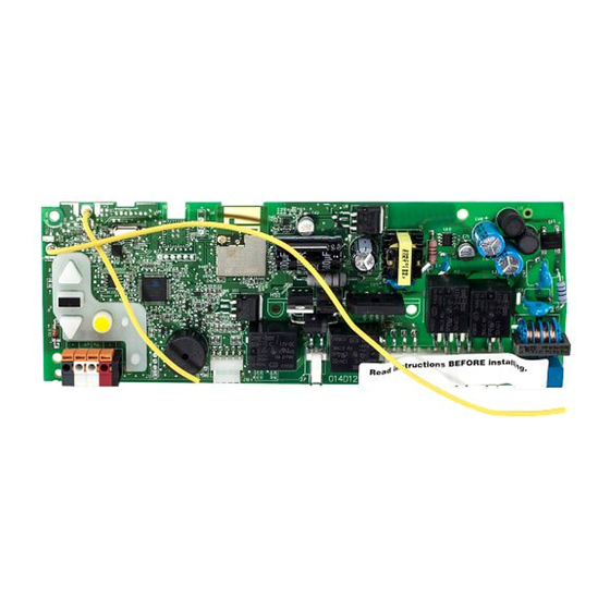
To prevent damage to the receiver/logic board, DO NOT touch printed
circuit board of replacement receiver/logic board during installation.
ALWAYS wear protective gloves and eye protection when changing the
battery or working around the battery compartment.
WARNING: This product can expose you to chemicals including
lead, which are known to the State of California to cause cancer or
birth defects or other reproductive harm. For more information go
to www.P65Warnings.ca.gov.
2
Remove the receiver logic board
2.1 Disconnect the wires from the quick-connect terminals
(A). Disconnect any wires from the lock terminals.
Remove the receiver logic board end panel from the
garage door opener.
A
Lock
Terminals
To insert or remove the wires from the terminal,
push in the tab with a screwdriver tip.
1.1 Remove the light lens by pulling
the top side of the light lens
and swing the light lens down.
Squeeze the light lens clips to
remove lens from end panel.
2.2 Unplug the wire harnesses from the receiver logic
board. You may need needle-nosed pliers, to
remove the harnesses.
1
RECEIVER LOGIC BOARD REPLACEMENT
Models 050DCTB and 050DCTBLK
NOTE: 050DCTB replaces 050DCTWF and 050DCTBLK replaces 050DCTWFLK.
®
serial number found on the provided label to add your
1.2 To maintain your warranty,
place the provided label
over the existing label
on the end panel of the
garage door opener.
2.3 Remove the receiver
logic board from the
end panel by removing
the 2 screws and
releasing the 2 clips.
Clips
1.3 Disconnect electrical and battery
power (if applicable) to the
garage door opener.
Screws
Wire clip
Advertisement
Table of Contents

Related Manuals for Chamberlain 050DCTB


Summary of Contents for Chamberlain 050DCTB
- Page 1 RECEIVER LOGIC BOARD REPLACEMENT Models 050DCTB and 050DCTBLK NOTE: 050DCTB replaces 050DCTWF and 050DCTBLK replaces 050DCTWFLK. Installation Before you begin Your garage door opener has an internal gateway located on the receiver logic board. After installing the new receiver logic board, use the myQ ®...
- Page 2 Install new receiver logic board 3.1 Connect the wire harnesses to the 3.2 Insert the antenna wires through 3.3 Reinsert the wires. For garage door openers without a battery new receiver logic board. When the holes in the end panel. Snap the Door control wires: back up system: remove the button pad from •...
-
Page 3: Program The Travel
Adjustment Program the travel 1.1 Press and hold the Adjustment Button 1.2 Press and hold the UP Button until the 1.3 Once the door is in the desired until the UP Button begins to fl ash and/ door is in the desired UP position. UP position press and release the or a beep is heard. -
Page 4: Test The Safety Reversal System
Test the Safety Reversal System 2.1 With the door fully open, place a 1-1/2 2.2 Press the remote control or wall-mounted door control If the door stops but does not inch (3.8 cm) board (or a 2x4 laid fl at) to close the door. -
Page 5: Installation
REMPLACEMENT DE LA CARTE LOGIQUE DU RÉCEPTEUR Modèles 050DCTB et 050DCTBLK REMARQUE: le modèle 050DCTB remplace le 050DCTWF et le modèle 050DCTBLK remplace le 050DCTWFLK. Installation Avant de commencer Votre ouvre-porte de garage est doté d’une passerelle interne située sur la carte logique du récepteur. Après avoir installé la nouvelle carte logique du récepteur, utiliser le numéro de série de la myQ ®... - Page 6 Installez le nouvelle carte logique du récepteur Pour les ouvre-portes de garage sans système 3.1 Connectez les harnais de fi ls à la 3.2 Insérez les fi ls d’antenne à travers les 3.3 Réinsérez les fi ls. Fils de commande de la porte : à...
- Page 7 Réglages Programmation de la course 1.1 Appuyer sur le bouton de réglage 1.2 Appuyer sur le bouton UP et le 1.3 Une fois que la porte est dans la et le maintenir enfoncé jusqu’à maintenir enfoncé jusqu’à ce que position d’ouverture désirée, appuyer ce que le bouton UP commence à...
-
Page 8: Essai Du Protector System
Essai du système d’inversion de sécurité Si la porte arrête sa course, mais ne 2.1 La porte étant entièrement 2.2 Appuyer sur le bouton de la télécommande ou de la l’inverse pas : ouverte, placer une planche de commande de porte montée au mur pour fermer la 1. -
Page 9: Antes De Comenzar
REEMPLAZO DE LA TARJETA LÓGICA DEL RECEPTOR Modelos 050DCTB y 050DCTBLK NOTA: El modelo 050DCTB reemplaza al 050DCTWF y el modelo 050DCTBLK reemplaza al 050DCTWFLK. Installation Antes de comenzar Su abre-puerta de garaje tiene un procesador de comunicaciones interno ubicado en la tarjeta lógica del receptor. Después de instalar la nueva tarjeta lógica del receptor utilice el número de serie del ®... - Page 10 Instale la nueva tarjeta lógica del receptor 3.2 Inserte los cables de la antena a través 3.3 Vuelva a insertar los cables. Para abre-puertas de garaje sin batería de 3.1 Conecte el hato de cables a la nueva Cables de control de la puerta: de los orifi...
- Page 11 Ajustes Programación de la carrera 1.1 Oprima y mantenga oprimido el 1.2 Oprima y mantenga oprimido el 1.3 Una vez que la puerta esté en la botón ajuste hasta que el botón botón ARRIBA hasta que la puerta posición deseada, oprima y suelte el ARRIBA empiece a parpadear y/o se encuentre en la posición Botón ajuste.
- Page 12 Para sincronizar el control fi jo con el abre-puerta pulsar el control hasta que se active el abre-puerta (podría llevar hasta tres intentos). Prueba el control de la puerta a pulsar el pulsadora de barra, cada vez que se pulsa el control fi jo se activará el mecanismo del abre-puerta. © 2020, The Chamberlain Group, Inc. All Rights Reserved Tous droits réservés...