Table of Contents
Advertisement
Quick Links
Advertisement
Chapters
Table of Contents
Troubleshooting

Related Manuals for Juniper EX9253


Summary of Contents for Juniper EX9253
- Page 1 EX9253 Switch Hardware Guide Published 2022-07-01...
- Page 2 The Juniper Networks product that is the subject of this technical documentation consists of (or is intended for use with) Juniper Networks software. Use of such software is subject to the terms and conditions of the End User License Agreement ("EULA") posted at https:/ /support.juniper.net/support/eula/.
-
Page 3: Table Of Contents
Environmental Requirements and Specifications for an EX9253 Switch | 50 General Site Guidelines | 51 Site Electrical Wiring Guidelines | 52 Clearance Requirements for Airflow and Hardware Maintenance for an EX9253 Switch | 53 Rack and Cabinet Requirements for EX9253 Switches | 54... - Page 4 Connecting the EX9253 to Power | 82 Connecting Earth Ground to an EX9253 Switch | 82 Connecting AC Power to an EX9253 Switch and Powering on the Switch | 85 Connecting DC Power to an EX9253 Switch and Powering on the Switch | 87...
- Page 5 Installing the Air Filter Unit in an EX9253 Switch | 117 Removing the Air Filter from the Air Filter Unit in an EX9253 Switch | 118 Installing the Air Filter in the Air Filter Unit in an EX9253 Switch | 120...
- Page 6 Removing a DC Power Supply in an EX9253 Switch | 127 Installing a DC Power Supply in an EX9253 Switch | 129 Maintaining Power Supplies in EX9253 Switches | 131 Maintaining the EX9253 Routing Engine | 132 Removing a Routing Engine from an EX9253 Switch | 132...
- Page 7 Returning an EX9253 Switch or Component for Repair or Replacement | 188 Locating the Serial Number on an EX9253 Switch or Component | 189 Locating the Serial Number ID Label on an EX9253 Switch Chassis | 190 Locating Serial Number ID Labels on FRU Components | 190...
- Page 8 Multiple Power Supplies Disconnection Warning | 233 TN Power Warning | 234 Agency Approvals for EX9253 Switches | 235 Compliance Statements for EMC Requirements for EX Series Switches | 237 Compliance Statements for Acoustic Noise for EX Series Switches | 242...
-
Page 9: About This Guide
Use this guide to install hardware and perform initial software configuration, routine maintenance, and troubleshooting for the EX9253 switch. After completing the installation and basic configuration procedures covered in this guide, refer to the Junos OS documentation for information about further software configuration. -
Page 10: Overview
C HAPTER Overview EX9253 System Overview | 2 EX9253 Chassis | 12 EX9253 Cooling System | 21 EX9253 Power System | 27 EX9253 Line Cards | 34... -
Page 11: Ex9253 System Overview
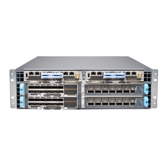
The EX9253 switch has a throughput of up to 2.4 terabits per second (Tbps). The EX9253 switch is a modular system that provides redundancy for all major hardware components, including Routing Engine and power supplies. - Page 12 Chassis Physical Specifications The EX9253 switch is three rack units (3 U) in size. Each EX9253 switch is designed to optimize rack space and cabling. Figure 1 on page...
- Page 13 The host subsystem consists of two Routing Engines. You must install either one or two Routing Engines in slots labeled RE0 and RE1 on the front panel of the chassis. A base configuration EX9253 switch has one Routing Engine. A redundant configuration...
- Page 14 "EX9253 Cooling System" on page 21). Power Supplies Power supplies for the EX9253 switch are fully redundant, load-sharing, and hot-removable and hot- insertable FRUs. Each EX9253 switch chassis can hold up to six AC or DC power supplies. The power...
- Page 15 1600 W AC 180–260 VAC 1100 W DC –40 VDC through –72 VDC A base configuration EX9253 switch ships with three power supplies. A redundant configuration EX9253 switch ships with four power supplies. See "EX9253 Power System" on page 27 "EX9253 Switch Configurations"...
-
Page 16: Ex9253 Switch Configurations
The air filter unit is installed on the cable management brackets. EX9253 Switch Configurations Table 3 on page 7 lists the hardware configurations for an EX9253 switch and the components included in each configuration. Table 3: EX9253 Switch Hardware Configurations... - Page 17 (Continued) Table 3: EX9253 Switch Hardware Configurations Switch Configuration Configuration Components Model Number First Junos Release Cable management bracket and air JNP-CM-3RU filter unit Blank panels for empty slots EX9253-LC-BLNK EX9253-BASE-DC Chassis EX9253-CHAS-3RU 18.2R1 One routing engine EX9253-RE Four fan trays...
- Page 18 (Continued) Table 3: EX9253 Switch Hardware Configurations Switch Configuration Configuration Components Model Number First Junos Release EX9253-RED-DC Chassis EX9253-CHAS-3RU 18.2R1 Two routing engines EX9253-RE Four fan trays JNP-FAN-3RU Four DC power supplies JNP-PWR1100-DC Cable management bracket and air JNP-CM-3RU filter unit...
-
Page 19: Ex9253 Switch Hardware And Cli Terminology Mapping
EX9253 Switch Hardware and CLI Terminology Mapping This topic describes the hardware terms used in EX9253 switch documentation and the corresponding terms used in the Junos OS CLI. See Table 4 on page Table 4: CLI Equivalents of Terms Used in Documentation for EX9253 Switches... - Page 20 (Continued) Table 4: CLI Equivalents of Terms Used in Documentation for EX9253 Switches Hardware Description (CLI) Value (CLI) Item in Additional Information Item (CLI) Documentation n is a value in the range FPC ( Abbreviated name Line card (The switch •...
-
Page 21: Ex9253 Chassis
Understanding EX9253 Switch Component and Functionality Redundancy | 20 Chassis Physical Specifications of an EX9253 Switch The EX9253 switch chassis is a rigid sheet-metal structure that houses all components of the switch. EX9253 is available in two variants—with AC power supply and with DC power supply. -
Page 22: Field-Replaceable Units In An Ex9253 Switch
You can mount an EX9253 switch on four posts of a 19-in. rack or cabinet. Field-Replaceable Units in an EX9253 Switch Field-replaceable units (FRUs) are components that you can replace at your site. The FRUs in EX9253 switches are hot-removable and hot-insertable. You can remove and replace them without powering off the switch. - Page 23 "Removing the Air Filter Unit from an EX9253 Switch" on page 116. To install the air filter in the air filter unit in an EX9253 switch, follow instructions in "Installing the Air Filter in the Air Filter Unit in an EX9253 Switch" on page 120.
-
Page 24: Host Subsystem In An Ex9253 Switch
To install a line card in an EX9253 switch, follow instructions in "Installing a Line Card in an EX9253 Switch" on page 143. To remove a line card from an EX9253 switch, follow instructions in "Removing a Line Card from an EX9253 Switch" on page 140. - Page 25 Management port (MGMT) BITS port with LEDs — — Console port (CON) Clocking ports — — SSD LEDs OFFLINE button — — SSDs ONLINE LED — — Master LED (MST) OK/FAIL LED — — Alarm LED (ALM) RESET button — —...
- Page 26 • USB—The USB port provides a removable media interface. Junos OS supports USB version 1.0 and later. Table 6 on page 17 describes the functions of the LEDs on the REs. Table 6: LEDs on the Routing Engines in an EX9253 Switch Color State Description...
- Page 27 (Continued) Table 6: LEDs on the Routing Engines in an EX9253 Switch Color State Description Major—Indicates a critical On steadily condition that can cause the switch to stop functioning. Possible causes include component removal, failure, or overheating, or any major software failure.
- Page 28 (Continued) Table 6: LEDs on the Routing Engines in an EX9253 Switch Color State Description – There is no alarm. SSD0 Green Blinking SSD0 is being accessed by the switch. – SSD0 is not active or not being accessed. SSD1...
-
Page 29: Understanding Ex9253 Switch Component And Functionality Redundancy
Redundancy The Juniper Networks EX9253 Ethernet Switches are available as fully redundant system. A redundant EX9253 switch configuration is designed so that no single point of failure can cause the entire switch to fail. See "EX9253 Switch Configurations" on page The following hardware components provide redundancy to an EX9253 switch: •... -
Page 30: Ex9253 Cooling System
Airflow Direction in the EX9253 Switch Chassis | 26 The cooling system in an EX9253 switch consists of four fan trays and an air filter unit. The cooling system components work together to keep all switch components within the acceptable temperature... -
Page 31: Fan Tray
Fan Tray The fan tray is a hot-insertable and hot-removable field-replaceable unit (FRU) and contains two counter-rotating fans (see Figure 8 on page 22 Figure 9 on page 23). The fan trays install vertically in the rear of the switch. Figure 8: Fan Tray... - Page 32 Figure 9: Faceplate of the Fan Tray Captive screw Status LED — — Latch — The fan trays and power supplies are hot-removable and hot-insertable field-replaceable units installed in the rear panel of the switch. You can replace them without powering off the switch or disrupting switch functions.
-
Page 33: Air Filter Unit
Air Filter Unit The air filter unit has three parts–the outer filter cover, the air filter, and the inner cage that form the body (see Figure 10 on page 24). The air filter is in between the outer filter cover and the inner cage. The air filter unit is mounted on the cable management brackets, and are held tightly by captive screws. -
Page 34: Fan Tray Status Leds
Fan Tray Status LEDs The LEDs indicating the state of the fan trays are located adjacent to the fan tray slots on the rear panel of the chassis (see Figure 11 on page 25 Table 7 on page 25). Figure 11: Fan Tray Status LEDs Captive screw Status LED —... -
Page 35: Cooling System In The Power Supplies
Air is pulled through the chassis toward the fan tray, where it is exhausted out through the rear of the chassis. The air intake to cool the power supplies is also located in the front of the chassis. Figure 12: Airflow Through the EX9253 Switch Chassis... -
Page 36: Ex9253 Power System
RELATED DOCUMENTATION Clearance Requirements for Airflow and Hardware Maintenance for an EX9253 Switch | 53 EX9253 Power System IN THIS SECTION AC Power Supply Description | 27 AC Power Cord Specifications for an EX9253 Switch | 29 AC Power Supply Specifications for EX9253 Switches | 31... - Page 37 — — Each power supply has its own fan and is cooled by its own internal cooling system. EX9253 switches support 800 W and 1600 W AC power supply. The AC power supply supports the low line (90 through 140 VAC) and the high line (180 through 264 VAC) AC power configurations. Each AC power supply has a single AC appliance inlet located on the power supply that requires a dedicated AC power feed.
-
Page 38: Ac Power Cord Specifications For An Ex9253 Switch
AC Power Cord Specifications for an EX9253 Switch A detachable AC power cord is supplied with the AC power supplies. The coupler is type C13 as described by International Electrotechnical Commission (IEC) standard 60320. The plug end of the power cord fits into the power source outlet that is standard for your geographical location. - Page 39 (Continued) Table 8: AC Power Cord Specifications Country/Region Electrical Specifications Plug Standards Juniper Model Number Israel 250 VAC, 10 A, 50 Hz SI 32/1971 Type IL/3G CBL-EX-PWR-C13-IL Italy 250 VAC, 10 A, 50 Hz CEI 23-16 Type I/3G CBL-EX-PWR-C13-IT Japan...
-
Page 40: Ac Power Supply Specifications For Ex9253 Switches
AC Power Supply Specifications for EX9253 Switches Table 9 on page 31 lists the AC power system electrical specifications. Table 9: AC Power System Electrical Specifications Item Specification AC input voltage Operating range: • AC low line: 90 through 140 VAC •... -
Page 41: Dc Power Supply Description
Status LED Handle — — Each power supply has its own fan and is cooled by its own internal cooling system. EX9253 switches support 1100 W DC power supply. Each DC power supply has terminals located on the power supply... -
Page 42: Dc Power Supply Specifications For Ex9253 Switches
40 A (–48 VDC) minimum, or as required by local code. Doing so enables you to operate the switch in any configuration without upgrading the power infrastructure. DC Power Supply Specifications for EX9253 Switches Table 11 on page 33 lists the DC power system electrical specifications. -
Page 43: Ex9253 Line Cards
Table 13 on page 34 lists the power requirements for various hardware components when the switch is operating under typical and maximum voltage conditions. Table 13: Power Requirements for EX9253 Components Component Power Requirement at 25° C Power Requirement at 55° C (Watts;... -
Page 44: Ex9253-6Q12C Line Card
OK/FAIL LED and ONLINE LED on EX9253-6Q12C Line Card | 40 The line cards in EX9253 switches combine a Packet Forwarding Engine and Ethernet interfaces in a single assembly. Line cards are field-replaceable units (FRUs) that you can install in the line card slots on the front of the switch chassis. - Page 45 Figure 18 on page Figure 18: EX9253-6Q12C Line Card Ejector levers ONLINE LED — — Lane LEDs OFFLINE button — — LEDs for the QSFP28 ports QSFP+ ports — — LEDs for the QSFP+ ports QSFP28 ports — — OK/FAIL LED —...
- Page 46 1.2 terabits of bandwidth. Thus, you can transmit up to 1.2 terabits of traffic through a port group, without packet drop. Port LEDs and Lane LEDs on EX9253-6Q12C Line Card You can select a port operating in a breakout mode for an individual lane display, either periodically or when the request chassis port-led command is executed.
- Page 47 • Selection of breakout port for lane display Up state are skipped and are not considered for lane NOTE: Ports with all individual links in display, thereby reducing the time needed to cycle through all the ports. Table 15 on page 38 describes the state and color rules for the port LEDs.
- Page 48 (Continued) Table 15: Port LED State and Color Rules Pluggable Breakout Explicitly Port State Normal Port Lane Inserted Configuration Disabled Location ON Display State Breakout All breakout ports are Green Blinking Blinking green green Breakout All breakout ports are Blinking Blinking down with LOS green...
- Page 49 OK/FAIL LED and ONLINE LED on EX9253-6Q12C Line Card Table 17 on page 40 describes the OK/FAIL LED and the ONLINE LED on EX9253-6Q12C line card, their colors and state, and the status they indicate. Table 17: OK/FAIL LED and ONLINE LED on EX9253-6Q12C Line Card...
-
Page 50: Ex9253-6Q12C-M Line Card
OK/FAIL LED and ONLINE LED on EX9253-6Q12C-M Line Card | 46 The line cards in EX9253 switches combine a Packet Forwarding Engine and Ethernet interfaces in a single assembly. Line cards are field-replaceable units (FRUs) that you can install in the line card slots on the front of the switch chassis. - Page 51 Figure 19 on page Figure 19: EX9253-6Q12C-M Line Card Ejector levers ONLINE LED — — Lane LEDs OFFLINE button — — LEDs for the QSFP28 ports QSFP+ ports — — LEDs for the QSFP+ ports QSFP28 ports (with MACsec capability) —...
- Page 52 1.2 terabits of bandwidth. Thus, you can transmit up to 1.2 terabits of traffic through a port group, without packet drop. Port LEDs and Lane LEDs on EX9253-6Q12C-M Line Card You can select a port operating in a breakout mode for an individual lane display, either periodically or when the request chassis port-led command is executed.
- Page 53 • Change in configuration • Activation or deactivation of port location feature • Selection of breakout port for lane display Up state are skipped and are not considered for lane NOTE: Ports with all individual links in display, thereby reducing the time needed to cycle through all the ports. Table 19 on page 44 describes the state and color rules for the port LEDs.
- Page 54 (Continued) Table 19: Port LED State and Color Rules Pluggable Breakout Explicitly Port State Normal Port Lane Inserted Configuration Disabled Location ON Display State Anything except Blinking – disabled port; green however, transceiver not present Breakout All breakout ports are Green Blinking Blinking...
- Page 55 OK/FAIL LED and ONLINE LED on EX9253-6Q12C-M Line Card Table 21 on page 46 describes the OK/FAIL LED and the ONLINE LED on EX9253-6Q12C-M line card, their colors and state, and the status they indicate. Table 21: OK/FAIL LED and ONLINE LED on EX9253-6Q12C-M Line Card...
-
Page 56: Site Planning, Preparation, And Specifications
C HAPTER Site Planning, Preparation, and Specifications Site Preparation Checklist for an EX9253 Switch | 48 EX9253 Site Guidelines and Requirements | 50 EX9253 Network Cable and Transceiver Planning | 57 EX9253 Management Cable Specifications and Pinouts | 67... -
Page 57: Site Preparation Checklist For An Ex9253 Switch
Site Preparation Checklist for an EX9253 Switch The checklist in Table 22 on page 48 summarizes the tasks you need to perform to prepare a site for installing an EX9253 switch. Table 22: Site Preparation Checklist Item or Task For More Information... - Page 58 • Ensure that the distance between hardware components to be connected allows for cable lengths to be within the specified maximum limits. RELATED DOCUMENTATION General Safety Guidelines and Warnings Installing and Connecting an EX9253 Switch | 77...
-
Page 59: Ex9253 Site Guidelines And Requirements
General Site Guidelines | 51 Site Electrical Wiring Guidelines | 52 Clearance Requirements for Airflow and Hardware Maintenance for an EX9253 Switch | 53 Rack and Cabinet Requirements for EX9253 Switches | 54 Environmental Requirements and Specifications for an EX9253 Switch The switch must be installed in a rack or cabinet housed in a dry, clean, well-ventilated, and temperature-controlled environment. -
Page 60: General Site Guidelines
(Continued) Table 23: EX9253 Switch Environmental Tolerances Description Value Temperature Normal operation ensured in temperature range of 32° F (0° C) through 104° F (40°C) Nonoperating storage temperature in shipping container: – 40° F (–40°C) through 158° F (70°C) Seismic... -
Page 61: Site Electrical Wiring Guidelines
Site Electrical Wiring Guidelines Table 24 on page 52 describes the factors you must consider while planning the electrical wiring at your site. WARNING: You must provide a properly grounded and shielded environment and use electrical surge-suppression devices. Avertissement Vous devez établir un environnement protégé et convenablement mis à la terre et utiliser des dispositifs de parasurtension. -
Page 62: Clearance Requirements For Airflow And Hardware Maintenance For An Ex9253 Switch
Clearance Requirements for Airflow and Hardware Maintenance for an EX9253 Switch When planning the site for installing an EX9253 switch, you must allow sufficient clearance around the switch. • For the cooling system to function properly, the airflow around the chassis must be unrestricted. -
Page 63: Rack And Cabinet Requirements For Ex9253 Switches
Figure 20: Clearance Requirements for Airflow and Hardware Maintenance for an EX9253 Switch Chassis Rack and Cabinet Requirements for EX9253 Switches You can mount an EX9253 switch on four-posts of a 19-in rack or in a cabinet that contains a 19-in. rack. Rack requirements consist of: •... - Page 64 Table 25: Rack Requirements and Specifications Rack Requirement Guidelines Rack type You can mount the device on a rack that provides bracket holes or hole patterns spaced at 1 U (1.75 in. or 4.45 cm) increments and meets the size and strength requirements to support the weight.
- Page 65 Table 26: Cabinet Requirements and Specifications Cabinet Requirement Guidelines Cabinet size • You can mount the device in a cabinet that contains a 19-in. rack as defined by the Electronic Components Industry Association (http:/ /www.ecianow.org). • The minimum cabinet size must be able to accommodate the maximum external dimensions of the device.
-
Page 66: Ex9253 Network Cable And Transceiver Planning
Calculating the Fiber-Optic Cable Power Margin for EX Series Devices | 65 Pluggable Transceivers Supported on an EX9253 Switch The line cards in EX9253 switches support transceivers. You can find the list of transceivers supported on EX9253 switches and information about those transceivers at the Hardware Compatibility Tool page EX9253. -
Page 67: Sfp+ Direct Attach Copper Cables For Ex Series Switches
Any damage to the host equipment due to the use of third-party optical modules or cables is the users’ responsibility. Juniper Networks will accept no liability for any damage caused due to such use. The Gigabit Ethernet transceivers installed in EX9253 switches support digital optical monitoring... - Page 68 Juniper Networks. If you face a problem running a Juniper device that uses third-party optical modules or cables, JTAC may help you diagnose host-related issues if the observed issue is not, in the opinion of JTAC, related to the use of the third-party optical modules or cables.
- Page 69 • EX8216—Hardware Compatibility Tool page for EX8216 • EX9251—Hardware Compatibility Tool page for EX9251 • EX9253—Hardware Compatibility Tool page for EX9253 Standards Supported by These Cables The cables comply with the following standards: • SFP mechanical standard SFF-843— see ftp:/ /ftp.seagate.com/sff/SFF-8431.PDF.
-
Page 70: Qsfp+ Direct Attach Copper Cables For Ex Series Switches
IN THIS SECTION Cable Specifications | 61 DAC Cables Supported on EX3400, EX4300, EX4550, EX4600, EX9251, and EX9253 Switches | 62 Quad small form-factor pluggable plus (QSFP+) direct attach copper (DAC) cables are suitable for in-rack connections between QSFP+ ports on EX3400, EX4300, EX4550, EX4600, EX9251, and EX9253 switches. -
Page 71: Understanding Ex Series Switches Fiber-Optic Cable Signal Loss, Attenuation, And Dispersion
Figure 22: QSFP+ Direct Attach Copper Cables DAC Cables Supported on EX3400, EX4300, EX4550, EX4600, EX9251, and EX9253 Switches For the list of DAC cables supported on EX3400, EX4300, EX4550, EX4600, EX9251, and EX9253 switches and the specifications of these cables, see: •... - Page 72 To determine the power budget and power margin needed for fiber-optic connections, you need to understand how signal loss, attenuation, and dispersion affect transmission. EX Series switches use various types of network cable, including multimode and single-mode fiber-optic cable. Signal Loss in Multimode and Single-Mode Fiber-Optic Cable Multimode fiber is large enough in diameter to allow rays of light to reflect internally (bounce off the walls of the fiber).
-
Page 73: Calculating The Fiber-Optic Cable Power Budget For Ex Series Devices
factor. However, at higher bit rates and over longer distances, chromatic dispersion limits the maximum link length. An efficient optical data link must have enough light to exceed the minimum power that the receiver requires to operate within its specifications. In addition, the total dispersion must be within the limits specified for the type of link in Telcordia Technologies document GR-253-CORE (Section 4.3) and International Telecommunications Union (ITU) document G.957. -
Page 74: Calculating The Fiber-Optic Cable Power Margin For Ex Series Devices
Calculating the Fiber-Optic Cable Power Margin for EX Series Devices Before calculating the power margin: Calculating the Fiber-Optic Cable Power Budget for EX Series • Calculate the power budget (see Devices Calculate the link's power margin when planning fiber-optic cable layout and distances to ensure that fiber-optic connections have sufficient signal power to overcome system losses and still satisfy the minimum input requirements of the receiver for the required performance level. - Page 75 (Continued) Table 27: Estimated Values for Factors Causing Link Loss Link-Loss Factor Estimated Link-Loss Value Sample (LL) Calculation Values Connector 0.5 dBm This example assumes 5 connectors. Loss for 5 connectors: (5) * (0.5 dBm) = 2.5 dBm Splice 0.5 dBm This example assumes 2 splices.
-
Page 76: Ex9253 Management Cable Specifications And Pinouts
EX9253 Management Cable Specifications and Pinouts IN THIS SECTION Management Cable Specifications | 67 Console Port Connector Pinout Information | 68 USB Port Specifications for an EX Series Switch | 69 RJ-45 to DB-9 Serial Port Adapter Pinout Information | 69... -
Page 77: Console Port Connector Pinout Information
Console Port Connector Pinout Information The console port on a Juniper Networks device is an RS-232 serial interface that uses an RJ-45 connector to connect to a console management device. The default baud rate for the console port is 9600 baud. -
Page 78: Usb Port Specifications For An Ex Series Switch
RJ-45 to DB-9 Serial Port Adapter Pinout Information The console port on a Juniper Networks device is an RS-232 serial interface that uses an RJ-45 connector to connect to a management device such as a laptop or a desktop PC. If your laptop or... -
Page 79: Rj-45 Management Port Connector Pinout Information
DB-9 pin Signal RJ-45 Management Port Connector Pinout Information Table 31 on page 70 provides the pinout information for the RJ-45 connector for the management port on Juniper Networks devices. Table 31: RJ-45 Management Port Connector Pinout Information Signal Description TRP1+ Transmit/receive data pair 1 TRP1—... - Page 80 (Continued) Table 31: RJ-45 Management Port Connector Pinout Information Signal Description TRP3+ Transmit/receive data pair 3 TRP3— Transmit/receive data pair 3 TRP2— Transmit/receive data pair 2 TRP4+ Transmit/receive data pair 4 TRP4— Transmit/receive data pair 4...
-
Page 81: Initial Installation And Configuration
C HAPTER Initial Installation and Configuration Unpacking and Mounting the EX9253 Switch | 73 Connecting the EX9253 to Power | 82 Connecting the EX9253 to External Devices | 91 Connecting the EX9253 to the Network | 99 Configuring Junos OS on the EX9253 | 103... -
Page 82: Unpacking And Mounting The Ex9253 Switch
Unpacking an EX9253 Switch | 73 Parts Inventory (Packing List) for an EX9253 Switch | 74 Unpacking a Line Card Used in an EX9253 Switch | 76 Register Products—Mandatory to Validate SLAs | 77 Installing and Connecting an EX9253 Switch | 77... -
Page 83: Parts Inventory (Packing List) For An Ex9253 Switch
Switch Configurations" on page 7 for more information. If any part on the packing list is missing, contact your customer service representative or contact Juniper customer care from within the U.S. or Canada by telephone at 1-888-314-5822. For international-dial or direct-dial options in countries without toll-free numbers, see https:/ /www.juniper.net/support/... - Page 84 (Continued) Table 32: Parts List for Different EX9253 Switch Configurations Component Base Configuration Quantity Redundant Configuration Quantity Cable management bracket Air filter unit Blank panels for empty slots One blank panel for each slot not One blank panel for each slot not...
-
Page 85: Unpacking A Line Card Used In An Ex9253 Switch
• Ensure that you know how to handle and store the line card (see The line cards for EX9253 switches are rigid sheet-metal structures that house the line card components including network ports. The line cards are shipped in a cardboard carton, secured with foam packing... -
Page 86: Register Products-Mandatory To Validate Slas
Update your installation base at https:/ /www.juniper.net/customers/csc/management/ updateinstallbase.jsp. Installing and Connecting an EX9253 Switch The EX9253 switch chassis is a rigid sheet-metal structure that houses the other hardware components such as Routing Engine, line cards, power supplies, fan trays, and air filter. -
Page 87: Mounting An Ex9253 Switch On A Rack Or Cabinet
4. Follow instructions for connecting power as appropriate for your site: • "Connecting AC Power to an EX9253 Switch and Powering on the Switch" on page 85 • "Connecting DC Power to an EX9253 Switch and Powering on the Switch" on page 87 5. - Page 88 • Cover panels for empty slots • Eight screws to secure the switch to the rack—not provided You can mount an EX9253 switch on four posts of a 19-in. (450 mm) rack as defined by the Electronic Components Industry Association (http:/ /www.ecianow.org) by using the mounting brackets provided...
- Page 89 To mount the switch on a rack: 1. Position the switch in front of the rack. 2. Wrap and fasten one end of an ESD wrist strap around your bare wrist, and connect the other end of the strap to the ESD point on the switch. NOTE: The rear mounting brackets on either side of the chassis are movable;...
- Page 90 5. Lift the switch by using material-handling systems (such as levers, slings, lifts, and so on). If that is not practical, have a specially trained person hold on to the bottom of the chassis on each side and carefully lift it. The front mounting brackets must contact the rack rails and the holes on the front mounting brackets must align with the threaded holes on the rack.
-
Page 91: Connecting The Ex9253 To Power
IN THIS SECTION Connecting Earth Ground to an EX9253 Switch | 82 Connecting AC Power to an EX9253 Switch and Powering on the Switch | 85 Connecting DC Power to an EX9253 Switch and Powering on the Switch | 87... - Page 92 To ensure proper operation and to meet safety and electromagnetic interference (EMI) requirements, you must connect an EX9253 switch to earth ground before you connect power to the switch. You must use the protective earthing terminal on the switch chassis to connect the switch to earth ground (see Figure 28 on page 84).
- Page 93 Grounding point — 6. Secure the grounding lug on the grounding cable to the protective earthing terminal on the switch by using the screws (see Figure 29 on page 84). Figure 29: Connecting a Grounding Cable to an EX9253 Switch...
-
Page 94: Connecting Ac Power To An Ex9253 Switch And Powering On The Switch
Connecting AC Power to an EX9253 Switch and Powering on the Switch Before you begin to connect AC power and power on the switch, ensure that you have the following parts and tools available: •... - Page 95 Push the power cord into the slot in the adjustment nut of the power cord retainer clip. Turn the nut until it is tight against the base of the coupler (see Figure 30 on page 86). Figure 30: Connecting Power to an AC-Powered Switch If the AC power source outlet has a power switch, set it to the off position.
-
Page 96: Connecting Dc Power To An Ex9253 Switch And Powering On The Switch
13. On the external management device, monitor the startup process to verify that the switch has booted properly. Connecting DC Power to an EX9253 Switch and Powering on the Switch Before you begin to connect DC power and power on the switch, ensure that you have the following parts and tools available: •... - Page 97 NOTE: Grounding is required for models that use DC power supplies. You connect DC power to the switch by attaching power cables from the DC power source to the terminals on the power supply faceplate. CAUTION: A licensed electrician must attach the ring lugs to the DC power cables. WARNING: Before connecting the switch to a DC power source, ensure that the cable leads will not become active while you are connecting DC power and that the voltage across the DC power source cable leads is 0 V.
- Page 98 external DC power source at your site determines the color coding for the leads on the power cables that attach to the terminal studs on each power supply. Remove the nuts from the terminals. Save the nuts. CAUTION: Ensure that each power cable lug seats flush against the surface of the terminal block as you are tightening the nuts.
- Page 99 b. Secure the negative (–) DC source power cable lug to the – 48V terminal (labeled –48V). Figure 31: Connecting Power to a DC-Powered Switch Verify that the power cabling is correct. Ensure that cables do not touch the switch components, block the air exhaust and access to switch components, or drape where people could trip on them.
-
Page 100: Connecting The Ex9253 To External Devices
Connect a Device to a Network for Out-of-Band Management | 91 Connect a Device to a Management Console Using an RJ-45 Connector | 92 Connecting the EX9253 Switch to External Clocking and Timing Devices | 94 Configuring Clock Synchronization Interface on EX9251 and EX9253 Switches | 95 Connect a Device to a Network for Out-of-Band Management Ensure that you have an Ethernet cable that has an RJ-45 connector at either end. -
Page 101: Connect A Device To A Management Console Using An Rj-45 Connector
You can monitor and manage these devices by using a dedicated management channel. Each device has a management port to which you can connect an Ethernet cable with an RJ-45 connector. Use the management port to connect the device to the management device. To connect a device to a network for out-of-band management (see Figure 33 on page 92):... - Page 102 NOTE: If your laptop or desktop PC does not have a DB-9 plug connector pin and you want to connect your laptop or desktop PC directly to the device, use a combination of the RJ-45 to DB-9 socket adapter supplied with the device and a USB to DB-9 plug adapter. You must provide the USB to DB-9 plug adapter.
-
Page 103: Connecting The Ex9253 Switch To External Clocking And Timing Devices
Connecting the EX9253 Switch to External Clocking and Timing Devices IN THIS SECTION Connecting 1-PPS and 10-MHz Timing Devices to the Switch | 94 Connecting a BITS External Clocking Device to the Switch | 95 The switch supports external clock synchronization for Synchronous Ethernet and external inputs. The connections to the switch are made through the ports on the front panel. -
Page 104: Connecting A Bits External Clocking Device To The Switch
Synchronous Ethernet, T1 or E1 line timing sources, and external inputs. Starting with Junos OS Release 18.2R1, EX9253 switches support external clock synchronization for Synchronous Ethernet, T1 or E1 line timing sources, and external inputs. Configuring external clock synchronization requires making clock selection, quality level, and priority considerations. - Page 105 In configuration mode, go to the [edit chassis synchronization] hierarchy level. [edit] user@host# edit chassis synchronization Configure the Synchronous Ethernet clock selection mode as auto-select or free-run to select the clock source either from an external qualified clock or from a free-run local oscillator. [edit chassis synchronization] user@host# set clock-mode (auto-select | free-run) Enable Ethernet Synchronization Message Channel (ESMC) packet transmission on all interfaces or...
- Page 106 the ESMC or SSM quality level that is configured for a qualifying interface or the received-quality option to use the ESMC or SSM quality that is received on the qualifying interface. [edit chassis synchronization] user@host# set selection-mode (configured-quality | received-quality) Configure the switchover mode as revertive or non-revertive.
- Page 107 minutes user@host# set wait-to-restore time user@host# set hold-off-time 10. Configure the options for the external interfaces. a. Go to the [edit chassis synchronization interfaces external] hierarchy level. [edit chassis synchronization] user@host# edit interfaces external b. Configure the frequency for the provided reference clock. [edit chassis synchronization interfaces external] user@host# set signal-type ( 2048KHZ |e1 | t1) c.
-
Page 108: Connecting The Ex9253 To The Network
Example: Configuring Synchronous Ethernet on MX Series Routers request chassis synchronization mode show chassis synchronization (MX Series Routers) synchronization Understanding Clock Synchronization Connecting the EX9253 to the Network IN THIS SECTION Install a Transceiver | 99 Connect a Fiber-Optic Cable | 102 Install a Transceiver... - Page 109 Juniper Networks. If you face a problem running a Juniper device that uses third-party optical modules or cables, JTAC may help you diagnose host-related issues if the observed issue is not, in the opinion of JTAC, related to the use of the third-party optical modules or cables.
- Page 110 LASER WARNING: Do not leave a fiber-optic transceiver uncovered except when inserting or removing a cable. The rubber safety cap keeps the port clean and prevents accidental exposure to laser light. 4. If the port in which you want to install the transceiver is covered with a dust cover, remove the dust cover and save it in case you need to cover the port later.
-
Page 111: Connect A Fiber-Optic Cable
CAUTION: Do not let fiber-optic cable hang free from the connector. Do not allow fastened loops of cable to dangle, which stresses the cable at the fastening point. CAUTION: Avoid bending fiber-optic cable beyond its minimum bend radius. An arc smaller than a few inches in diameter can damage the cable and cause problems that are difficult to diagnose. -
Page 112: Configuring Junos Os On The Ex9253
Connecting and Configuring an EX9253 Switch | 104 EX9253 Switch Default Configuration Each EX9253 switch is programmed with a factory default configuration that contains the values set for each configuration parameter when a switch is shipped. The default configuration file sets values for... -
Page 113: Connecting And Configuring An Ex9253 Switch
• IP address of a DNS server • Password for the root user The EX9253 switch is shipped with the Junos OS preinstalled and ready to be configured when the switch is powered on. There are two 16-MB internal NAND Flash memory devices located on the... - Page 114 baseboard for BIOS storage. You can insert the USB storage device into the USB slot on the front panel. The switch also has two built-in M.2-based solid-state drives (SSDs) (labeled SSD0 and SSD1). There are three copies of the software: one each on the SSD drives and one on a USB flash drive that can be inserted into the slot in the faceplate of the Routing Engine.
- Page 115 Configure the IP address and prefix length for the switch’s management Ethernet interface. [edit] address/prefix-length root@# set interfaces fxp0 unit 0 family inet address Configure the IP address of a backup router, which is used only when the routing protocol is not running.
- Page 116 10. (Optional) Configure the static routes to remote subnets with access to the management port. Access to the management port is limited to the local subnet. To access the management port from a remote subnet, you must add a static route to that subnet within the routing table. [edit] remote-subnet next-hop destination-IP retain no- root@# set routing-options static route...
- Page 117 14. Commit the configuration to activate it on the switch. [edit] root@host# commit 15. Exit the configuration mode. [edit] root@host# exit root@host> NOTE: Ensure that the removable storage media that contains a copy of Junos OS is not installed in the switch except when you want to install Junos OS from the storage media. If the storage media is installed during normal operation and if the switch is rebooted intentionally or accidentally (for example, as a result of a power outage), the configuration in the switch is deleted and the copy of the software in the storage media is installed in the switch.
-
Page 118: Maintaining Components
C HAPTER Maintaining Components Routine Maintenance Procedures for EX9253 Switches | 110 Maintaining the EX9253 Cooling System | 110 Maintaining the EX9253 Power System | 122 Maintaining the EX9253 Routing Engine | 132 Maintaining the EX9253 Line Cards | 136... -
Page 119: Routine Maintenance Procedures For Ex9253 Switches
Purpose | 110 Action | 110 Purpose For optimum performance of an EX9253 switch, perform preventive maintenance procedures. Action • Inspect the installation site for moisture, loose wires or cables, and excessive dust. Make sure that airflow is unobstructed around the switch and into the air intake vents. -
Page 120: Removing A Fan Tray From An Ex9253 Switch
Installing the Air Filter Unit in an EX9253 Switch | 117 Removing the Air Filter from the Air Filter Unit in an EX9253 Switch | 118 Installing the Air Filter in the Air Filter Unit in an EX9253 Switch | 120... -
Page 121: Installing A Fan Tray In An Ex9253 Switch
Figure 40: Removing a Fan Tray SEE ALSO EX9253 Cooling System | 21 Installing a Fan Tray in an EX9253 Switch Before you begin to install a fan tray: Prevention of • Ensure you understand how to prevent electrostatic discharge (ESD) damage (ee... - Page 122 4. Tighten the screw on the fan tray faceplate using the Phillips (+) screwdriver, number 2 to secure the fan tray in the chassis. Figure 41: Installing a Fan Tray NOTE: If you have a Juniper J-Care service contract, register any addition, change, or upgrade of hardware components at https:/ /www.juniper.net/customers/support/tools/updateinstallbase/ Failure to do so can result in significant delays if you need replacement parts.
-
Page 123: Maintaining The Fan Tray In Ex9253 Switches
Maintaining the Fan Tray in EX9253 Switches IN THIS SECTION Purpose | 114 Action | 114 Purpose For optimum cooling, verify the condition of the fans. Action • Monitor the status of the fans. A fan tray contains multiple fans that work in unison to cool the switch components. - Page 124 FPC 0 EA0_HMC0 Logic die 84 degrees C / 183 degrees F FPC 0 EA0_HMC0 DRAM botm 81 degrees C / 177 degrees F FPC 0 EA0_HMC1 Logic die 86 degrees C / 186 degrees F FPC 0 EA0_HMC1 DRAM botm 83 degrees C / 181 degrees F FPC 0 EA0_HMC2 Logic die 87 degrees C / 188 degrees F...
-
Page 125: Removing The Air Filter Unit From An Ex9253 Switch
Removing the Air Filter Unit from an EX9253 Switch Before you begin to remove the air filter unit, ensure that you have the following parts and tools available: • A Phillips (+) screwdriver, number 2 (not provided) • A replacement air filter unit... -
Page 126: Installing The Air Filter Unit In An Ex9253 Switch
Figure 42 on page 117). Figure 42: Removing the Air Filter Unit Installing the Air Filter Unit in an EX9253 Switch Before you begin to install the air filter unit, ensure that you have a Phillips (+) screwdriver, number 2 available. -
Page 127: Removing The Air Filter From The Air Filter Unit In An Ex9253 Switch
4. Tighten the captive screws to secure the air filter unit. Removing the Air Filter from the Air Filter Unit in an EX9253 Switch Before you begin to remove the air filter, ensure that you have the following parts and tools available: •... - Page 128 or other materials into the switch chassis through the unfiltered air intake. This could damage the switch and its components. To remove the air filter: 1. Wrap and fasten one end of an ESD wrist strap around your bare wrist, and connect the other end of the strap to the ESD point on the switch.
-
Page 129: Installing The Air Filter In The Air Filter Unit In An Ex9253 Switch
Installing the Air Filter in the Air Filter Unit in an EX9253 Switch Before you begin to install the air filter, ensure that you have a Phillips (+) screwdriver, number 2 available. WARNING: Ensure that you understand how to prevent ESD damage (see... -
Page 130: Maintaining The Air Filter In Ex9253 Switches
4. Grasp the air filter, and place the air filter straight in front of the inner cage. 5. Place the outer cover back in its place. 6. Tighten the captive screws to secure the air filter unit. Maintaining the Air Filter in EX9253 Switches IN THIS SECTION Purpose | 121... -
Page 131: Maintaining The Ex9253 Power System
This could damage the switch components. • EX9253 switches ship with one air filter. Spare air filters are separately orderable. The shelf life of the air filters vary from two to five years depending on the storage conditions. Store spare air filters in a dark, cool, and dry place. - Page 132 • Ensure that you have taken the necessary precautions to prevent electrostatic discharge (ESD) Prevention of Electrostatic Discharge Damage damage (See • Ensure that you have the following parts and tools available to power off an EX9253 switch: • An ESD wrist strap • An external management device such as a PC •...
-
Page 133: Removing An Ac Power Supply From An Ex9253 Switch
• A replacement power supply or a cover panel for the power supply slot The AC power supply in an EX9253 switch is a hot-removable and hot-insertable field-replaceable unit (FRU). You can remove and replace it while the switch is running without turning off power to the switch or disrupting switching functions. -
Page 134: Installing An Ac Power Supply In An Ex9253 Switch
(FRU). You can remove and replace it while the switch is running without turning off power to the switch or disrupting switching functions. You can install up to six power supplies in an EX9253 switch. A minimum of two high line power supplies or three low line must be installed in the switch for non- redundant operation. - Page 135 CAUTION: EX9253 switches use either AC or DC power supplies. Do not mix AC and DC power supplies in a switch. NOTE: Each AC power supply must be connected to a dedicated AC power source outlet. To install an AC power supply in an EX9253 switch (see...
-
Page 136: Removing A Dc Power Supply In An Ex9253 Switch
• A replacement power supply or cover panel for the power supply slot The DC power supply in an EX9253 switch is a hot-removable and hot-insertable field-replaceable unit (FRU). You can remove and replace it while the switch is running without turning off power to the switch or disrupting switching functions. - Page 137 NOTE: After powering off a power supply, wait for at least 60 seconds before turning it back on. To remove a DC power supply from an EX9253 switch: Switch off the dedicated customer site circuit breaker for the power supply being removed. Follow your site's procedures for ESD.
-
Page 138: Installing A Dc Power Supply In An Ex9253 Switch
(FRU). You can remove and replace it while the switch is running without turning off power to the switch or disrupting switching functions. You can install up to six DC power supplies in an EX9253 switch. The power supplies are installed in the slots labeled PSM0 through PSM5 on the rear of the chassis. - Page 139 Figure 50: Installing a DC Power Supply NOTE: If you have a Juniper J-Care service contract, register any addition, change, or upgrade of hardware components at https:/ /www.juniper.net/customers/support/tools/updateinstallbase/ Failure to do so can result in significant delays if you need replacement parts.
-
Page 140: Maintaining Power Supplies In Ex9253 Switches
On a regular basis: • Check the status of the power supplies by issuing the show chassis environment pem command. The output for EX9253 switches is similar to the following: user@switch> show chassis environment pem • Make sure that the power and grounding cables are arranged so that they do not obstruct access to other switch components. -
Page 141: Maintaining The Ex9253 Routing Engine
• A replacement RE or a cover panel for the RE slot The Routing Engine (RE) in an EX9253 switch is a hot-removable and hot-insertable field-replaceable unit (FRU). You can remove and replace it while the switch is running without turning off power to the switch or disrupting switching functions if RE graceful switchover is configured in the CLI. - Page 142 • To remove the primary RE: user@switch>request vmhost halt • To remove the backup RE: user@switch>request vmhost halt slot-number You must specify the number of the slot in which the RE is installed—RE0 or RE1. • To remove both the REs: user@switch>request vmhost halt routing-engine both 2.
-
Page 143: Installing A Routing Engine In An Ex9253 Switch
• A Phillips (+) screwdriver, number 2 The Routing Engine (RE) in an EX9253 switch is a hot-removable and hot-insertable field-replaceable unit (FRU). You can remove and replace it while the switch is running without turning off power to the switch or disrupting switching functions. - Page 144 Background 0 percent Kernel 0 percent Interrupt 0 percent Idle 99 percent Model EX9253-RE Start time 2018-04-29 20:19:29 PDT Uptime 56 days, 10 hours, 22 minutes, 39 seconds Last reboot reason 0x2000:hypervisor reboot Load averages: 1 minute 5 minute 15 minute 0.08...
-
Page 145: Maintaining The Ex9253 Line Cards
Maintaining the EX9253 Line Cards IN THIS SECTION Handling and Storing Line Cards | 137 Maintaining Line Card Cables | 140 Removing a Line Card from an EX9253 Switch | 140 Installing a Line Card in an EX9253 Switch | 143... -
Page 146: Handling And Storing Line Cards
Handling and Storing Line Cards IN THIS SECTION Holding a Line Card | 137 Storing a Line Card | 139 Components in the line cards are fragile. To avoid damaging the line cards, follow the procedures in this topic. The procedures use the following terms to describe the four edges of the line cards: •... - Page 147 To hold a line card horizontally: 1. Orient the line card so that the faceplate faces you. 2. Grasp the top edge with your left hand and the bottom edge with your right hand. You can rest the faceplate of the line card against your body as you carry it. CAUTION: Take care not to hit the line card against any object as you carry it.
-
Page 148: Storing A Line Card
Do not rest any edge of a line card directly against a hard surface. See Figure Figure 54: Do Not Rest the Edge of a Line Card on a Hard Surface If you must rest a line card temporarily on an edge, place a cushion between the edge and the surface. -
Page 149: Maintaining Line Card Cables
• Label both ends of line card cables to identify them. Removing a Line Card from an EX9253 Switch Before you begin to remove a line card from an EX9253 switch: • Ensure that you have taken the necessary precautions to prevent electrostatic discharge (ESD) Prevention of Electrostatic Discharge Damage damage. - Page 150 • Ensure that you know how to handle and store the line card (see Maintaining Line Card Cables and maintain line card cables (see Ensure that you have the following parts and tools available to remove a line card from an EX9253 switch chassis: • ESD grounding strap •...
- Page 151 Do this to protect the interior of the chassis from dust or other foreign substances and to ensure that the airflow inside the chassis is not disrupted. Figure 55: Removing a Line Card SEE ALSO EX9253-6Q12C Line Card | 35...
-
Page 152: Installing A Line Card In An Ex9253 Switch
NOTE: A fully configured line card can weigh up to 18.35 lb (8.3 kg). Be prepared to support the full weight. EX9253 switches have field-replaceable unit (FRU) line cards that can be installed in the line card slots on the front of the switch chassis. The line cards are hot-insertable and hot-removable: You can remove and replace them without powering off the switch or disrupting switch functions. - Page 153 CAUTION: Do not lift the line card by holding the ejector handles on the faceplate or the edge connectors. A fully configured line card can weigh up to 18.35 lb (8.3 kg). The ejector handles cannot support the weight of the line card. Lifting the line card by the ejector handles might bend them.
-
Page 154: Maintaining Transceivers
You can verify that the line card is functioning correctly by issuing the show chassis fpc and show chassis fpc pic-status commands. NOTE: If you have a Juniper J-Care service contract, register any addition, change, or upgrade of hardware components at https:/ /www.juniper.net/customers/support/tools/updateinstallbase/... -
Page 155: Remove A Transceiver
• Rubber safety caps to cover the transceiver and fiber-optic cable connector • A dust cover to cover the port or a replacement transceiver The transceivers for Juniper Networks devices are hot-removable and hot-insertable field-replaceable units (FRUs): You can remove and replace them without powering off the device or disrupting device functions. - Page 156 LASER WARNING: Do not leave a fiber-optic transceiver uncovered except when inserting or removing a cable. The rubber safety cap keeps the port clean and prevents accidental exposure to laser light. CAUTION: Do not bend fiber-optic cables beyond their minimum bend radius. An arc smaller than a few inches in diameter can damage the cables and cause problems that are difficult to diagnose.
-
Page 157: Install A Transceiver
CAUTION: To prevent ESD damage to the transceiver, do not touch the connector pins at the end of the transceiver. Figure 57: Remove a QSFP+ Transceiver Ejector lever — To remove a CFP transceiver: a. Loosen the screws on the transceiver by using your fingers. b. - Page 158 Juniper Networks. If you face a problem running a Juniper device that uses third-party optical modules or cables, JTAC may help you diagnose host-related issues if the observed issue is not, in the opinion of JTAC, related to the use of the third-party optical modules or cables.
- Page 159 LASER WARNING: Do not leave a fiber-optic transceiver uncovered except when inserting or removing a cable. The rubber safety cap keeps the port clean and prevents accidental exposure to laser light. 4. If the port in which you want to install the transceiver is covered with a dust cover, remove the dust cover and save it in case you need to cover the port later.
-
Page 160: Remove A Qsfp28 Transceiver
• A dust cover to cover the port or a replacement transceiver The transceivers for Juniper Networks devices are hot-removable and hot-insertable field-replaceable units (FRUs). You can remove and replace them without powering off the device or disrupting the device... - Page 161 6 seconds for the interface to display operational commands. NOTE: We recommend that you use only optical transceivers and optical connectors purchased from Juniper Networks with your Juniper Networks device. To remove a QSFP28 transceiver (see Figure 59 on page 153): 1.
-
Page 162: Install A Qsfp28 Transceiver
Ensure that you have a rubber safety cap available to cover the transceiver. The transceivers for Juniper Networks devices are hot-removable and hot-insertable field-replaceable units (FRUs): You can remove and replace them without powering off the device or disrupting the device functions. - Page 163 Juniper Networks. If you face a problem running a Juniper device that uses third-party optical modules or cables, JTAC may help you diagnose host-related issues if the observed issue is not, in the opinion of JTAC, related to the use of the third-party optical modules or cables.
-
Page 164: Maintain Fiber-Optic Cables
LASER WARNING: Do not look directly into a fiber-optic transceiver or into the ends of fiber-optic cables. Fiber-optic transceivers and fiber-optic cable connected to a transceiver emit laser light that can damage your eyes. CAUTION: Do not leave a fiber-optic transceiver uncovered except when inserting or removing cable. -
Page 165: Connect A Fiber-Optic Cable
Connect a Fiber-Optic Cable Before you connect a fiber-optic cable to an optical transceiver installed in a device, ensure that you Laser and LED Safety Guidelines have taken the necessary precautions for safe handling of lasers (see and Warnings To connect a fiber-optic cable to an optical transceiver installed in a device: LASER WARNING: Do not look directly into a fiber-optic transceiver or into the ends of fiber-optic cables. -
Page 166: Disconnect A Fiber-Optic Cable
• A rubber safety cap to cover the transceiver • A rubber safety cap to cover the fiber-optic cable connector Juniper Networks devices have optical transceivers to which you can connect fiber-optic cables. To disconnect a fiber-optic cable from an optical transceiver installed in the device: 1. - Page 167 • When you unplug a fiber-optic cable from a transceiver, place rubber safety caps over the transceiver and on the end of the cable. • Anchor fiber-optic cables to prevent stress on the connectors. When attaching a fiber-optic cable to a transceiver, be sure to secure the fiber-optic cable so that it does not support its own weight as it hangs to the floor.
-
Page 168: Troubleshooting Hardware
C HAPTER Troubleshooting Hardware Troubleshooting EX9253 Components | 160... -
Page 169: Troubleshooting Ex9253 Components
Troubleshooting EX9253 Components IN THIS SECTION Troubleshooting the Cooling System in an EX9253 Switch | 160 Troubleshooting the Power Supply in an EX9253 Switch | 161 Troubleshooting Line Cards in an EX9253 Switch | 163 Troubleshoot Temperature Alarms in EX Series Switches | 165... -
Page 170: Troubleshooting The Power Supply In An Ex9253 Switch
• The switch temperature exceeds the • The temperature of the switch exceeds the temperature hot threshold (major alarm and automatic shutdown of the power supplies). Troubleshooting the Power Supply in an EX9253 Switch IN THIS SECTION Problem | 162 Cause | 162... - Page 171 Problem Description The power system is not functioning normally. Cause Solution • Check the LEDs on each power supply faceplate. If a power supply is installed correctly and is functioning normally, the status LED lights steadily. • Issue the CLI show chassis environment pem command to check the status of the power supplies. As shown in the sample output, the value Online in the rows labeled State must indicate that each of the power supplies is functioning normally.
-
Page 172: Troubleshooting Line Cards In An Ex9253 Switch
LEDs indicate that the power supply is not operating normally, the power supply is the source of the problem. Replace the power supply with a spare. Troubleshooting Line Cards in an EX9253 Switch IN THIS SECTION Problem | 163... - Page 173 • Issue the show chassis fpc command to check the status of installed line cards. As shown in the sample output, the value Online in the column labeled Slot State indicates that the line card is functioning normally: user@switch> show chassis fpc Temp CPU Utilization (%) CPU Utilization (%) Memory Utilization...
-
Page 174: Troubleshoot Temperature Alarms In Ex Series Switches
Troubleshoot Temperature Alarms in EX Series Switches IN THIS SECTION Problem | 165 Cause | 165 Solution | 165 Problem Description EX Series switches generate a temperature alarm FPC 0 EX-PFE1 Temp Too Hot. Cause Temperature sensors in the chassis monitor the temperature of the chassis. The switch raises an alarm if a fan fails or if the temperature of the chassis exceeds permissible levels. - Page 175 show chassis environment (EX9208 Switch) user@switch> show chassis environment Class Item Status Measurement Temp PEM 0 40 degrees C / 104 degrees F PEM 1 40 degrees C / 104 degrees F PEM 2 Absent PEM 3 Absent Routing Engine 0 37 degrees C / 98 degrees F Routing Engine 0 CPU 35 degrees C / 95 degrees F...
- Page 176 FPC 3 PLX PCIe Switch TSe 51 degrees C / 123 degrees F FPC 3 PLX PCIe Switch Chi 54 degrees C / 129 degrees F FPC 3 Aloha FPGA 0 TSen 51 degrees C / 123 degrees F FPC 3 Aloha FPGA 0 Chip 70 degrees C / 158 degrees F FPC 3 Aloha FPGA 1 TSen 51 degrees C / 123 degrees F...
- Page 177 (Continued) Table 34: show chassis environment Output Fields Field Name Field Description Status Class Fans Status of the specified chassis component. For example, if , the fan status can be: • OK : The fans are operational. • Testing : The fans are being tested during initial power-on. •...
- Page 178 Table 35: show chassis temperature-thresholds Output Fields Field Name Field Description Item Chassis component. You can configure for the threshold information for components such as the chass the Routing Engines, and FPC for each slot in each FRU to display in the output. By default, informatio displayed only for the chassis and the Routing Engines.
- Page 179 Replace the faulty fan module or fan tray. • If the above two checks show no problems, open a support case using the Case Manager link at https:/ /www.juniper.net/support/ or call 1-888-314-5822 (toll-free within the United States and Canada) or 1-408-745-9500 (from outside the United States).
-
Page 180: Understand Alarm Types And Severity Levels On Ex Series Switches
NOTE: This topic applies only to the J-Web Application package. Alarms alert you to conditions that might prevent normal operation of the switch. Before monitoring alarms on a Juniper Networks EX Series Ethernet switch, become familiar with the terms defined in Table 37 on page 171. -
Page 181: Chassis Component Alarm Conditions On Ex9253 Switches
Chassis Component Alarm Conditions on EX9253 Switches IN THIS SECTION Backup Routing Engine Alarms | 177 This topic describes the chassis component alarm conditions on EX9253 switches. Table 38 on page 173 lists the alarms that the chassis components can generate on EX9253 switches. - Page 182 Table 38: Chassis Component Alarm Conditions on EX9253 Switches Chassis Alarm Condition Alarm Remedy Component Severity Alternative The switch boots from an Minor Open a support case using the Case media alternate boot device, the (yellow) Manager link at https:/ /www.juniper.net/ secondary SSD.
- Page 183 (Continued) Table 38: Chassis Component Alarm Conditions on EX9253 Switches Chassis Alarm Condition Alarm Remedy Component Severity A power supply has a high Major (red) Replace the failed power supply. temperature. A power supply input has failed. Major (red) Check power supply input connection.
- Page 184 (Continued) Table 38: Chassis Component Alarm Conditions on EX9253 Switches Chassis Alarm Condition Alarm Remedy Component Severity System booted from the default Minor Install the bootable image on the default backup Routing Engine. If you (yellow) primary Routing Engine. If this fails, replace manually switched primary role, the failed Routing Engine.
- Page 185 (Continued) Table 38: Chassis Component Alarm Conditions on EX9253 Switches Chassis Alarm Condition Alarm Remedy Component Severity Feature usage requires a license Minor Install the required license for the feature or the license for the feature (yellow) specified in the alarm. For more usage has expired.
- Page 186 (Continued) Table 38: Chassis Component Alarm Conditions on EX9253 Switches Chassis Alarm Condition Alarm Remedy Component Severity The temperature has exceeded Major (red) • Check room temperature. the defined threshold for the Fire Shutdown • condition listed in Check air filter and replace it, if show chassis required.
- Page 187 Open a support case using the Case Manager media boots from an alternate boot (yellow) link at https:/ /www.juniper.net/support/ or call device, the SSD. The primary 1-888-314-5822 (toll free, US & Canada) or SSD (SSD0) is typically the 1-408-745-9500 (from outside the United primary boot device.
-
Page 188: Monitor System Log Messages
1-888-314-5822 (toll free, US & Canada) or 1-408-745-9500 (from outside the United States). SEE ALSO Field-Replaceable Units in an EX9253 Switch | 13 Monitor System Log Messages IN THIS SECTION Purpose | 179 Action | 180 Meaning | 183 Purpose NOTE: This topic applies only to the J-Web Application package. - Page 189 Action To view events in the J-Web interface, select Monitor > Events and Alarms > View Events. Apply a filter or a combination of filters to view messages. You can use filters to display relevant events. Table 40 on page 180 describes the different filters, their functions, and the associated actions.
- Page 190 (Continued) Table 40: Filtering System Log Messages Field Function Your Action Date From Specifies the time period in which the To specify the time period: events you want displayed are • Click the Calendar icon and select the generated. year, month, and date— for example, Displays a calendar that allows you to 02/10/2007.
- Page 191 (Continued) Table 40: Filtering System Log Messages Field Function Your Action Generate Raw Report Generates a list of event log messages in To generate a raw report: nontabular format. NOTE: 1. Click Generate Raw Report. • Starting in Junos OS Opening filteredEvents.html Release 14.1X53, a window appears.
- Page 192 (Continued) Table 40: Filtering System Log Messages Field Function Your Action Generate Report Generates a list of event log messages in To generate a formatted report: tabular format, which shows system NOTE: Starting in Junos 1. Click Generate Report. details, events filter criteria, and event OS Release 14.1X53, a details.
- Page 193 Table 41: Viewing System Log Messages Field Function Additional Information Process Displays the name and ID of the process that The information displayed in this field is generated the system log message. different for messages generated on the local Routing Engine than for messages generated on another Routing Engine (on a system with two Routing Engines installed and operational).
- Page 194 (Continued) Table 41: Viewing System Log Messages Field Function Additional Information Event ID Displays a code that uniquely identifies the The event ID begins with a prefix that message. indicates the generating software process. The prefix on each code identifies the message Some processes on a switch do not use codes.
- Page 195 14.1X53 Starting in Junos OS Release 14.1X53, a Formatted Report can be generated from event log messages being loaded in an Events Detail table.
-
Page 196: Contacting Customer Support And Returning The Chassis Or Components
C HAPTER Contacting Customer Support and Returning the Chassis or Components Returning an EX9253 Chassis or Components | 188... -
Page 197: Returning An Ex9253 Chassis Or Components
Packing an EX9253 Switch or Component | 194 Returning an EX9253 Switch or Component for Repair or Replacement If you need to return a switch or hardware component to Juniper Networks for repair or replacement, follow this procedure: 1. Determine the serial number of the chassis if you need to return the switch. If you need to return one or more components, determine the serial number for each component. -
Page 198: Locating The Serial Number On An Ex9253 Switch Or Component
Locating Serial Number ID Labels on FRU Components | 190 If you are returning a switch or hardware component to Juniper Networks for repair or replacement, you must locate the serial number of the switch or component. You must provide the serial number to the... -
Page 199: Locating The Serial Number Id Label On An Ex9253 Switch Chassis
Locating the Serial Number ID Label on an EX9253 Switch Chassis The serial number ID label is located on the top of the chassis on an EX9253 switch (see Figure Figure 62: Location of the Serial Number ID Label on EX9253 Switch Chassis Locating Serial Number ID Labels on FRU Components Field-replaceable units (FRUs) are components that you can replace at your site. - Page 200 • Fan tray— The serial number ID label is on the base of the fan tray (see Figure 63 on page 191). Figure 63: Location of the Serial Number ID Label on a Fan Tray • AC power supply—The serial number ID label is on the top of the AC power supply (see Figure 64 on page 191).
- Page 201 • DC power supply—The serial number ID label is on the top of the DC power supply (see Figure 65 on page 192). Figure 65: Location of the Serial Number ID Label on a DC Power Supply • Line card—The serial number ID label is on the connector end (see Figure 66 on page 192).
-
Page 202: Contact Customer Support To Obtain Return Material Authorization
Replacing a QSFP28 Transceiver on an SRX4600 Services Gateway Contact Customer Support to Obtain Return Material Authorization If you are returning a device or hardware component to Juniper Networks for repair or replacement, obtain a Return Material Authorization (RMA) number from Juniper Networks Technical Assistance Center (JTAC). -
Page 203: Packing An Ex9253 Switch Or Component
Packing an EX9253 Switch | 195 Packing EX9253 Switch Components for Shipping | 196 If you are returning an EX9253 switch or component to Juniper Networks for repair or replacement, pack the item as described in this topic. Before you begin to pack the switch or component, ensure you have: Contact Customer Support to Obtain Return Material Authorization •... -
Page 204: Packing An Ex9253 Switch
Electrostatic Discharge Damage Packing an EX9253 Switch If you need to transport the switch to another location or return the switch to Juniper Networks, you need to pack the switch securely in its original packaging to prevent damage during transportation. -
Page 205: Packing Ex9253 Switch Components For Shipping
• Securely tape the box closed. • Write the RMA number on the exterior of the box to ensure proper tracking. RELATED DOCUMENTATION Parts Inventory (Packing List) for an EX9253 Switch | 74... -
Page 206: Safety And Compliance Information
C HAPTER Safety and Compliance Information General Safety Guidelines and Warnings | 199 Definitions of Safety Warning Levels | 200 Qualified Personnel Warning | 202 Warning Statement for Norway and Sweden | 202 Fire Safety Requirements | 203 Installation Instructions Warning | 204 Chassis and Component Lifting Guidelines | 205 Restricted Access Warning | 205 Ramp Warning | 207... - Page 207 Multiple Power Supplies Disconnection Warning | 233 TN Power Warning | 234 Agency Approvals for EX9253 Switches | 235 Compliance Statements for EMC Requirements for EX Series Switches | 237 Compliance Statements for Acoustic Noise for EX Series Switches | 242...
-
Page 208: General Safety Guidelines And Warnings
General Safety Guidelines and Warnings The following guidelines help ensure your safety and protect the device from damage. The list of guidelines might not address all potentially hazardous situations in your working environment, so be alert and exercise good judgment at all times. •... -
Page 209: Definitions Of Safety Warning Levels
• Some parts of the chassis, including AC and DC power supply surfaces, power supply unit handles, SFB card handles, and fan tray handles might become hot. The following label provides the warning of the hot surfaces on the chassis: •... - Page 210 dient u zich bewust te zijn van de bij elektrische schakelingen betrokken risico's en dient u op de hoogte te zijn van standaard maatregelen om ongelukken te voorkomen. Varoitus Tämä varoitusmerkki merkitsee vaaraa. Olet tilanteessa, joka voi johtaa ruumiinvammaan. Ennen kuin työskentelet minkään laitteiston parissa, ota selvää sähkökytkentöihin liittyvistä...
-
Page 211: Qualified Personnel Warning
Qualified Personnel Warning WARNING: Only trained and qualified personnel should install or replace the device. Waarschuwing Installatie en reparaties mogen uitsluitend door getraind en bevoegd personeel uitgevoerd worden. Varoitus Ainoastaan koulutettu ja pätevä henkilökunta saa asentaa tai vaihtaa tämän laitteen. Avertissement Tout installation ou remplacement de l'appareil doit être réalisé... -
Page 212: Fire Safety Requirements
In addition, you should establish procedures to protect your equipment in the event of a fire emergency. Juniper Networks products should be installed in an environment suitable for electronic equipment. We recommend that fire suppression equipment be available in the event of a fire in the vicinity of the equipment and that all local fire, safety, and electrical codes and ordinances be observed when you install and operate your equipment. -
Page 213: Installation Instructions Warning
NOTE: To keep warranties effective, do not use a dry chemical fire extinguisher to control a fire at or near a Juniper Networks device. If a dry chemical fire extinguisher is used, the unit is no longer eligible for coverage under a service agreement. -
Page 214: Chassis And Component Lifting Guidelines
Chassis and Component Lifting Guidelines • Before moving the device to a site, ensure that the site meets the power, environmental, and clearance requirements. • Before lifting or moving the device, disconnect all external cables and wires. • As when lifting any heavy object, ensure that most of the weight is borne by your legs rather than your back. - Page 215 pääsee jonkin erikoistyökalun, lukkoon sopivan avaimen tai jonkin muun turvalaitteen avulla ja joka on paikasta vastuussa olevien toimivaltaisten henkilöiden valvoma. Avertissement Cet appareil est à installer dans des zones d'accès réservé. Ces dernières sont des zones auxquelles seul le personnel de service peut accéder en utilisant un outil spécial, un mécanisme de verrouillage et une clé, ou tout autre moyen de sécurité.
-
Page 216: Ramp Warning
Ramp Warning WARNING: When installing the device, do not use a ramp inclined at more than 10 degrees. Waarschuwing Gebruik een oprijplaat niet onder een hoek van meer dan 10 graden. Varoitus Älä käytä sellaista kaltevaa pintaa, jonka kaltevuus ylittää 10 astetta. Avertissement Ne pas utiliser une rampe dont l'inclinaison est supérieure à... - Page 217 Les directives ci-dessous sont destinées à assurer la protection du personnel: • Le rack sur lequel est monté le Juniper Networks switch doit être fixé à la structure du bâtiment.
- Page 218 Le seguenti direttive vengono fornite per garantire la sicurezza personale: • Il Juniper Networks switch deve essere installato in un telaio, il quale deve essere fissato alla struttura dell'edificio. • Questa unità deve venire montata sul fondo del supporto, se si tratta dell'unica unità...
- Page 219 Para garantizar su seguridad, proceda según las siguientes instrucciones: • El Juniper Networks switch debe instalarse en un bastidor fijado a la estructura del edificio. • Colocar el equipo en la parte inferior del bastidor, cuando sea la única unidad en el...
-
Page 220: Grounded Equipment Warning
Följande riktlinjer ges för att trygga din säkerhet: • Juniper Networks switch måste installeras i en ställning som är förankrad i byggnadens struktur. • Om denna enhet är den enda enheten på ställningen skall den installeras längst ned på... -
Page 221: Radiation From Open Port Apertures Warning
Avvertenza Questo dispositivo deve sempre disporre di una connessione a massa. Seguire le istruzioni indicate in questa guida per connettere correttamente il dispositivo a massa. Advarsel Denne enheten på jordes skikkelig hele tiden. Følg instruksjonene i denne veiledningen for å jorde enheten. Aviso Este equipamento deverá... -
Page 222: Laser And Led Safety Guidelines And Warnings
Class 1 LED Product Warning | 215 Laser Beam Warning | 215 Juniper Networks devices are equipped with laser transmitters, which are considered a Class 1 Laser Product by the U.S. Food and Drug Administration and are evaluated as a Class 1 Laser Product per EN 60825-1 requirements. - Page 223 General Laser Safety Guidelines When working around ports that support optical transceivers, observe the following safety guidelines to prevent eye injury: • Do not look into unterminated ports or at fibers that connect to unknown sources. • Do not examine unterminated optical ports with optical instruments. •...
- Page 224 Class 1 LED Product Warning LASER WARNING: Class 1 LED product. Waarschuwing Klasse 1 LED-product. Varoitus Luokan 1 valodiodituote. Avertissement Alarme de produit LED Class I. Warnung Class 1 LED-Produktwarnung. Avvertenza Avvertenza prodotto LED di Classe 1. Advarsel LED-produkt i klasse 1. Aviso Produto de classe 1 com LED.
-
Page 225: Maintenance And Operational Safety Guidelines And Warnings
Aviso Não olhe fixamente para o raio, nem olhe para ele directamente com instrumentos ópticos. ¡Atención! No mirar fijamente el haz ni observarlo directamente con instrumentos ópticos. Varning! Rikta inte blicken in mot strålen och titta inte direkt på den genom optiska instrument. - Page 226 aanbevolen is. Gebruikte batterijen dienen overeenkomstig fabrieksvoorschriften weggeworpen te worden. Varoitus Räjähdyksen vaara, jos akku on vaihdettu väärään akkuun. Käytä vaihtamiseen ainoastaan saman- tai vastaavantyyppistä akkua, joka on valmistajan suosittelema. Hävitä käytetyt akut valmistajan ohjeiden mukaan. Avertissement Danger d'explosion si la pile n'est pas remplacée correctement. Ne la remplacer que par une pile de type semblable ou équivalent, recommandée par le fabricant.
- Page 227 Waarschuwing Alvorens aan apparatuur te werken die met elektrische leidingen is verbonden, sieraden (inclusief ringen, kettingen en horloges) verwijderen. Metalen voorwerpen worden warm wanneer ze met stroom en aarde zijn verbonden, en kunnen ernstige brandwonden veroorzaken of het metalen voorwerp aan de aansluitklemmen lassen.
- Page 228 Varning! Tag av alla smycken (inklusive ringar, halsband och armbandsur) innan du arbetar på utrustning som är kopplad till kraftledningar. Metallobjekt hettas upp när de kopplas ihop med ström och jord och kan förorsaka allvarliga brännskador; metallobjekt kan också sammansvetsas med kontakterna. Lightning Activity Warning WARNING: Do not work on the system or connect or disconnect cables during periods of lightning activity.
- Page 229 6 in. (15.2 cm) of clearance around the ventilation openings. Waarschuwing Om te voorkomen dat welke switch van de Juniper Networks router dan ook oververhit raakt, dient u deze niet te bedienen op een plaats waar de maximale aanbevolen omgevingstemperatuur van 40°...
- Page 230 ¡Atención! Para impedir que un encaminador de la serie Juniper Networks switch se recaliente, no lo haga funcionar en un área en la que se supere la temperatura ambiente máxima recomendada de 40° C. Para impedir la restricción de la entrada de aire, deje un espacio mínimo de 15,2 cm alrededor de las aperturas para ventilación.
-
Page 231: General Electrical Safety Guidelines And Warnings
General Electrical Safety Guidelines and Warnings WARNING: Certain ports on the device are designed for use as intrabuilding (within- GR-1089-CORE ) the-building) interfaces only (Type 2 or Type 4 ports as described in and require isolation from the exposed outside plant (OSP) cabling. To comply with NEBS requirements and protect against lightning surges and commercial power must not be metallically connected to interfaces disturbances, the intrabuilding ports... -
Page 232: Action To Take After An Electrical Accident
• Canada—Canadian Electrical Code, Part 1, CSA C22.1. • Suitable for installation in Information Technology Rooms in accordance with Article 645 of the National Electrical Code and NFPA 75. Peut être installé dans des salles de matériel de traitement de l’information conformément à l’article 645 du National Electrical Code et à... -
Page 233: Prevention Of Electrostatic Discharge Damage
Prevention of Electrostatic Discharge Damage Device components that are shipped in antistatic bags are sensitive to damage from static electricity. Some components can be impaired by voltages as low as 30 V. You can easily generate potentially damaging static voltages whenever you handle plastic or foam packing material or if you move components across plastic or carpets. -
Page 234: Ac Power Electrical Safety Guidelines
• When removing or installing a component that is subject to ESD damage, always place it component- side up on an antistatic surface, in an antistatic card rack, or in an antistatic bag (see Figure 68 on page 225). If you are returning a component, place it in an antistatic bag before packing it. Figure 68: Placing a Component into an Antistatic Bag CAUTION: ANSI/TIA/EIA-568 cables such as Category 5e and Category 6 can get electrostatically charged. -
Page 235: Ac Power Disconnection Warning
“ATTENTION: CET APPAREIL COMPORTE PLUS D'UN CORDON D'ALIMENTATION. AFIN DE PRÉVENIR LES CHOCS ÉLECTRIQUES, DÉBRANCHER TOUT CORDON D'ALIMENTATION AVANT DE FAIRE LE DÉPANNAGE.” • AC-powered devices are shipped with a three-wire electrical cord with a grounding-type plug that fits only a grounding-type power outlet. Do not circumvent this safety feature. Equipment grounding must comply with local and national electrical codes. -
Page 236: Dc Power Electrical Safety Guidelines
Avertissement Avant de travailler sur un châssis ou à proximité d'une alimentation électrique, débrancher le cordon d'alimentation des unités en courant alternatif. Warnung Bevor Sie an einem Chassis oder in der Nähe von Netzgeräten arbeiten, ziehen Sie bei Wechselstromeinheiten das Netzkabel ab bzw. Avvertenza Prima di lavorare su un telaio o intorno ad alimentatori, scollegare il cavo di alimentazione sulle unità... -
Page 237: Dc Power Disconnection Warning
NOTE: Primary overcurrent protection is provided by the building circuit breaker. This breaker must protect against excess currents, short circuits, and earth grounding faults in accordance with NEC ANSI/NFPA 70. • Ensure that the polarity of the DC input wiring is correct. Under certain conditions, connections with reversed polarity might trip the primary circuit breaker or damage the equipment. - Page 238 disjoncteur en position fermée (OFF) et, à l'aide d'un ruban adhésif, bloquer la poignée du disjoncteur en position OFF. Warnung Vor Ausführung der folgenden Vorgänge ist sicherzustellen, daß die Gleichstromschaltung keinen Strom erhält. Um sicherzustellen, daß sämtlicher Strom abgestellt ist, machen Sie auf der Schalttafel den Unterbrecher für die Gleichstromschaltung ausfindig, stellen Sie den Unterbrecher auf AUS, und kleben Sie den Schaltergriff des Unterbrechers mit Klebeband in der AUS-Stellung fest.
-
Page 239: Dc Power Grounding Requirements And Warning
DC Power Grounding Requirements and Warning An insulated grounding conductor that is identical in size to the grounded and ungrounded branch circuit supply conductors but is identifiable by green and yellow stripes is installed as part of the branch circuit that supplies the device. The grounding conductor is a separately derived system at the supply transformer or motor generator set. - Page 240 48 V. When disconnecting power, the proper wiring sequence is –48 V to –48 V, +RTN to +RTN, then ground to ground. Note that the ground wire must always be connected first and disconnected last. Waarschuwing De juiste bedradingsvolgorde verbonden is aarde naar aarde, +RTN naar +RTN, en –48 V naar –...
-
Page 241: Dc Power Wiring Terminations Warning
¡Atención! Wire a fonte de alimentação de DC Usando os talões apropriados nan EXtremidade da fiação. Ao conectar a potência, a seqüência apropriada da fiação é moída para moer, +RTN a +RTN, então –48 V a –48 V. Ao desconectar a potência, a seqüência apropriada da fiação é... -
Page 242: Multiple Power Supplies Disconnection Warning
Avvertenza Quando occorre usare trecce, usare connettori omologati, come quelli a occhiello o a forcella con linguette rivolte verso l'alto. I connettori devono avere la misura adatta per il cablaggio e devono serrare sia l'isolante che il conduttore. Advarsel Hvis det er nødvendig med flertrådede ledninger, brukes godkjente ledningsavslutninger, som for eksempel lukket sløyfe eller spadetype med oppoverbøyde kabelsko. -
Page 243: Tn Power Warning
Avertissement Cette unité est équipée de plusieurs raccordements d'alimentation. Pour supprimer tout courant électrique de l'unité, tous les cordons d'alimentation doivent être débranchés. Warnung Diese Einheit verfügt über mehr als einen Stromanschluß; um Strom gänzlich von der Einheit fernzuhalten, müssen alle Stromzufuhren abgetrennt sein. Avvertenza Questa unità... -
Page 244: Agency Approvals For Ex9253 Switches
Agency Approvals for EX9253 Switches IN THIS SECTION Compliance Statement for Argentina | 236 EX9253 switches comply with the following standards: • Safety • DCAN/CSA-C22.2 No. 60950-1 Information Technology Equipment - Safety • DUL 60950-1 (2nd Edition) Information Technology Equipment - Safety •... - Page 245 • AT& T TP-76200 Issue 17 (2012) Network Equipment Power, Grounding, Environmental, and Physical Design Requirements • Verizon TPR.9305 Issue 5 (2012) Verizon NEBS Compliance: NEBS Compliance Clarification Document • British Telecom EMC Immunity Requirements (2007) • Juniper Inductive GND (JIG) Compliance Statement for Argentina EQUIPO DE USO IDÓNEO.
-
Page 246: Compliance Statements For Emc Requirements For Ex Series Switches
Compliance Statements for EMC Requirements for EX Series Switches IN THIS SECTION Canada | 237 Taiwan | 238 European Community | 238 Israel | 239 Japan | 239 Korea | 239 United States | 240 FCC Part 15 Statement | 240 Nonregulatory Environmental Standards | 241 This topic applies to hardware devices in the EX Series product family, which includes EX Series switches, the EX Series Redundant Power System (RPS), and the XRE200 External Routing Engine. - Page 247 aware that compliance with the above conditions might not prevent degradation of service in some situations. Repairs to certified equipment should be made by an authorized Canadian maintenance facility designated by the supplier. Any repairs or alterations made by the user to this equipment, or equipment malfunctions, might give the telecommunications company cause to request the user to disconnect the equipment.
- Page 248 Israel The preceding translates as follows: Warning: This product is Class A. In residential environments, the product may cause radio interference, and in such a situation, the user may be required to take adequate measures. Japan The preceding translates as follows: This is a Class A device.
- Page 249 The preceding translates as follows: This equipment is Industrial (Class A) electromagnetic wave suitability equipment and seller or user should take notice of it, and this equipment is to be used in the places except for home United States The device has been tested and found to comply with the limits for a Class A digital device, pursuant to Part 15 of the FCC Rules.
- Page 250 • All EX8200 switches • EX9251 • EX9253 These switches meet the following NEBS compliance standards: • SR-3580 NEBS Criteria Levels (Level 4 Compliance) • GR-1089-CORE: EMC and Electrical Safety for Network Telecommunications Equipment •...
-
Page 251: Compliance Statements For Acoustic Noise For Ex Series Switches
• You must provision a readily accessible device outside of the equipment to disconnect power. The device must also be rated based on local electrical code practice. Compliance Statements for Acoustic Noise for EX Series Switches This topic applies to hardware devices in the EX Series product family, which includes EX Series switches, the EX Series Redundant Power System (RPS), and the XRE200 External Routing Engine.