Table of Contents
Advertisement
Quick Links
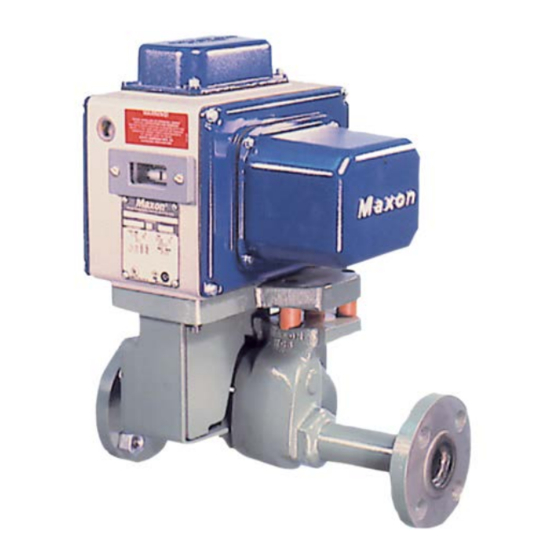
Maxon Oil Electro-mechanical
Valves
1/2" Series 8730
position "TO"
Please read the operating and mounting instructions before using the equipment. Install the
equipment in compliance with the prevailing regulations.
Bedrijfs- en montagehandleiding voor gebruik goed lezen! Apparaat moet volgens de geldende
voorschriften worden geïnstalleerd.
Lire les instructions de montage et de service avant utilisation! L'appareil doit imperativement
être installé selon les règlementations en vigueur.
Betriebs- und Montageanleitung vor Gebrauch lesen! Gerät muß nach den geltenden
Vorschriften installiert werden.
MANUFACTURER AND IMPORTER ADDRESSES
Below are the addresses and contact information for the Honeywell – Maxon manufacturing location and European sales office. The
European sales office serves as the importer and EU manufacturer's representative under the EU New Legislative Framework (NLF).
MUNCIE, INDIANA, USA – MANUFACTURER
201 East 18th Street
P.O. Box 2068
Muncie, IN 47307-0068
Tel: 765.284.3304
Fax: 765.286.8394
INSTRUCTION MANUAL
1" Series 4760
position "L"
EUROPEAN SALES OFFICE –
IMPORTER
BELGIUM
Maxon International BVBA
Luchthavenlaan 16-18
1800 Vilvoorde, Belgium
Tel: 32.2.255.09.09
Fax: 32.2.251.82.41
32M-95002-03
Advertisement
Table of Contents

Related Manuals for Honeywell MAXON 8730 Series


Summary of Contents for Honeywell MAXON 8730 Series
- Page 1 MANUFACTURER AND IMPORTER ADDRESSES Below are the addresses and contact information for the Honeywell – Maxon manufacturing location and European sales office. The European sales office serves as the importer and EU manufacturer's representative under the EU New Legislative Framework (NLF).
- Page 2 Nameplate and abbreviations WARNING Consult the nameplate of your valve. This lists the The installation, operation and maintenance maximum operating pressure, temperature limitations, instructions contain important information that voltage requirements and service conditions of your must be read and followed by anyone operating specific valve.
-
Page 3: Component Identification
COMPONENT IDENTIFICATION General Maintenance and Spare Parts To determine suggested spare parts, identify series All safety devices should be tested at least monthly* designation and serial number from the valve’s and more often if deemed advisable. Periodic testing for nameplate. Refer to the illustration and legend below to tightness motorized shut-off valve closure is equally identify suggested spare parts. - Page 4 AUXILIARY SIGNAL SWITCHES 8700 SERIES All Maxon proof-of-open and proof-of-closure signal switches work in a similar manner; but due to different styles and types of top assembly housings, the switches appear in slightly different positions in the various types of valves. Illustrated at right are representative top housings for .375"...
-
Page 5: Valve Open
AUXILIARY SIGNAL SWITCHES 4700(NI) & 33479 SERIES All Maxon valves may be equipped with internally- throw) switch. VCS-2 is a DPDT (double-pole, double- mounted signal switch(es) to provide a “proof-of-open” or throw) switch. All contacts are available for external “proof-of-closure” valve position indication. circuitry. -
Page 6: Installation
Installation 5. Maintain integrity of the electro-mechanical actuator enclosures by using the appropriate electrical connec- 1. A filter or strainer of 40 mesh (0.6 mm maximum) or tors for the (2) 3/4” NPT conduit threaded connec- greater is recommended in the fuel piping to protect tions. -
Page 7: Agency Approvals And Certifications
AGENCY APPROVALS AND CERTIFICATIONS Table 1. Approvals and Certifications. General Purpose Valves Non-Incendive/Non-Sparking Valves 4730, 4760 4730NI, 4760NI 8730, 8760 Standards Markings Standards Markings Class I, Div 2, Groups ABCD FM 7400 Class II, Div 2, Groups FG FM 3600 FM Approvals FM 7400 Class III, Div 2 FM 3611... - Page 8 VALVE MODEL NUMBER DESCRIPTION Table 3. Valve Model Number Description Configured Model Valve Body Actuator 0050 8700 Solenoid Voltage VOS Switch Valve Size 0038 -- 3/8” (DN 10) 0 -- None 1 -- VOS-1 Switch 0050 -- 1/2” (DN 15) A -- 115V 50HZ 2 -- VOS-2 Switch 0075 -- 3/4"...
- Page 9 ACTUATOR ASSEMBLY ROTATION 12. Energize valve and cycle several times from closed to full open position. Also electrically trip the valve in a partially opened position to prove valve operates prop- WARNING erly. 13. Replace and secure terminal block cover plate and MAXON electro-mechanical valves should be place valve in service.
-
Page 10: Maintenance Instructions
MAINTENANCE INSTRUCTIONS Actuator assembly components require no field lubrication and should never be oiled. MAXON electro-mechanical valves are endurance tested Auxiliary switches, solenoids, motors, clutches or circuit far in excess of the most stringent requirements of the boards may be replaced in the field. various approval agencies. - Page 11 E - i - 05/22 32M-95002-03...
- Page 12 For More Information The Honeywell Thermal Solutions family of products includes Honeywell Combustion Safety, Eclipse, Exothermics, Hauck, Kromschröder and Maxon. To learn more about our products, visit ThermalSolutions.honeywell.com or contact your Honeywell Sales Engineer. Honeywell MAXON branded products 201 E 18th Street Muncie, IN 47302 www.maxoncorp.com...