ABB AC500-S Safety User Manual
Hide thumbs
Also See for AC500-S:
- Safety user manual (452 pages) ,
- Application note (24 pages) ,
- System manual (119 pages)
Table of Contents
Advertisement
Quick Links
Advertisement
Table of Contents

Related Manuals for ABB AC500-S


Summary of Contents for ABB AC500-S
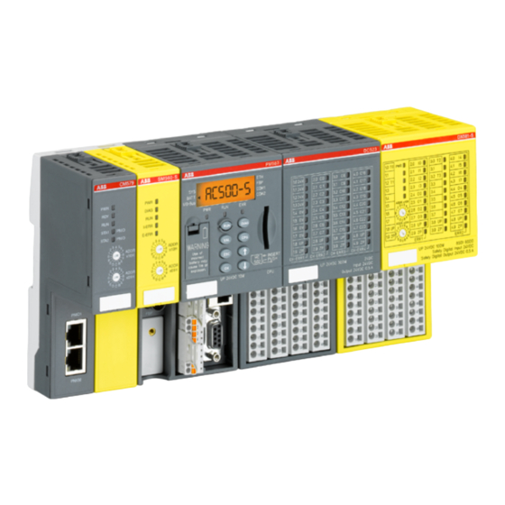
- Page 1 MANUAL AC500-S Safety user manual V1.2.0 Original instructions...
-
Page 2: Table Of Contents
2.6 Lifecycle..............................18 2.7 Installation of safety modules........................18 2.8 Exchange of modules..........................19 2.9 AC500-S restart behavior........................19 2.10 Replacing AC500-S safety PLC components..................19 2.11 Environmentally friendly disposal......................19 2.12 Safe communication..........................19 2.13 Safety function and fault reaction......................21 2.13.1... - Page 3 Working with PROFINET/PROFIsafe F-Devices..............131 4.3.5 Instantiation and configuration of safety modules / definition of variable names....133 4.3.6 Programming of AC500-S safety CPU................... 141 4.3.7 Checking of program and system configuration..............159 4.4 CODESYS Safety programming guidelines..................172 4.4.1 Overview..........................
- Page 4 6.2 Checklist for creation of safety application program................326 6.3 Checklist for configuration and wiring....................328 6.4 Checklist for operation, maintenance and repair................... 330 6.5 Verification procedure for safe iParameter setting in AC500-S safety I/Os........... 332 6.5.1 Verification procedure workflow..................... 333 6.5.2...
-
Page 5: Introduction
SIL 3 according to IEC 61508:2010, SILCL 3 according to IEC 62061:2015 and per- formance level e (cat. 4) according to ISO 13849-1:2015. ABB’s AC500 series is a PLC-based modular automation solution that makes it easy to mix and match safety and non-safety I/O modules to meet automation market requirements. - Page 6 Introduction Document history Rev. Description of version / changes Date 1.0.4 Various typos were corrected. Minor improvements in the text. 27.03.2017 Major changes: Licensing information was updated: ● Ch. 4.1: Notice Block with reference to PS501-S license installation removed. ● Ch.
-
Page 7: Validity
First release 19.12.2012 1.3 Validity The data and illustrations found in this documentation are not binding. ABB reserves the right to modify its products in line with its policy of continuous product development. 1.4 Important user information This documentation is intended for qualified personnel familiar with functional safety. You must read and understand the safety concepts and requirements presented in this safety user manual prior to operating AC500-S safety PLC system. -
Page 8: Definitions, Expressions, Abbreviations
ABB safety PLC for applications up to SIL 3 (IEC 61508), SILCL 3 (IEC 62061) and PL e (ISO 13849-1) AC500-S-XC ABB safety PLC for applications up to SIL 3 (IEC 61508), SILCL 3 (IEC 62061) and PL e (ISO 13849-1) suitable for extreme environmental conditions... - Page 9 OSSD Output signal switching device Passivation The passivation is the special state of safety I/O modules which leads to the delivery of safe substitute values, which are ‘0’ values in AC500-S, to the safety CPU. Personal computer PELV Protective extra low voltage...
-
Page 10: Functional Safety Certification
SILCL 3 according to IEC 62061:2015 and performance level e according to ISO 13849-1:2015, as certified by TÜV SÜD Rail GmbH (Germany). The AC500-S is a safety PLC which operation reliability is significantly improved compared to a non-safety PLC using 1oo2 redundancy in the hardware and additional diagnostic functions in its hardware and software. -
Page 11: References / Related Documents
1.7 References / related documents - Creation of safety-oriented applications with CODESYS V2.3 - Document version 1.8 - TÜV SÜD Rail Certification Report for AC500-S Safety PLC, Version - 2018 (or newer), available at www.abb.com/plc - PROFIsafe - Profile for Safety Technology on PROFIBUS DP and PROFINET IO Profile part, related to IEC 61784-3-3, Version 2.4, March, 2007 (or newer) - Page 12 Environmental testing - Part 2-64: Tests - Test Fh: Vibration, broadband random and guidance IEC 60068-2-78 2012 Environmental testing - Part 2-78: Tests - Test Cab: Damp heat, steady state NOTICE! Contact ABB technical support for further details. 3ADR025091M0208, 12, en_US 2020/06/19...
-
Page 13: Overview Of Ac500-S Safety Plc
2 Overview of AC500-S safety PLC 2.1 Overview The AC500-S is realized as 1oo2 system (both safety CPU and safety I/O modules) and can be used to handle safety functions with SIL 3 (IEC 61508), SILCL 3 (IEC 62061) and PL e (ISO 13849-1) requirements in high-demand systems of safety machinery applications and low- demand systems of safety process applications. -
Page 14: Safety Components
Non-safety CPU ABB’s complete AC500 range of non-safety CPUs can be used with safety CPU to create customized solutions - even for the most challenging requirements. The programming of safety and non-safety applications is offered via a non-safety PLC interface. - Page 15 Overview of AC500-S safety PLC Overview > Safety components SM560-S / SM560-S SM560-S-FD-1 / SM560-S-FD-4 DIAG I-ERR E-ERR ADDR x10H ADDR x01H Safety CPU (safety module) for up to SIL 3 (IEC 61508), SILCL 3 (IEC 62061) and PL e (ISO 13849-1) safety applications.
-
Page 16: Intended Use
Spring-type terminal unit TU582-S for safety I/O modules. 2.2 Intended use The user shall coordinate usage of ABB AC500-S safety components in his applications with the competent authorities and get their approval. ABB assumes no liability or responsibility for any consequences arising from the improper use: ●... -
Page 17: Safety Loop
Overview of AC500-S safety PLC Safety values 2.3 Safety loop The safety loop, to which the AC500-S safety PLC belongs, consists of the following three parts: sensors, safety PLC and actuators. Safety loop Safety PLC Safety Input Safety Output Safety CPU... -
Page 18: Qualified Personnel
ST, LAD and FBD programming languages). 2.6 Lifecycle All AC500-S safety modules have a maximum life of 20 years. This means that all AC500-S safety modules shall be taken out of service or replaced by new AC500-S safety modules at least one week before the expiry of 20 years (counted from the date of delivery by ABB). -
Page 19: Exchange Of Modules
Hardware components for AC500-S (safety CPU and safety I/Os) are replaced in the same way as in a non-safety AC500 automation system. - Page 20 Overview of AC500-S safety PLC Safe communication Fig. 3: Possible AC500-S system setup with PROFINET/PROFIsafe for remote safety I/Os, sensors and actuators PROFINET/PROFIsafe communication between AC500-S safety CPUs is supported using CM589-PNIO(-XC) and/or CM589-PNIO-4(-XC) PROFINET IO device communication modules together with SM560-S-FD-1(-XC) and/or SM560-S-FD-4(-XC) safety CPUs with F-Device func- tionality on one side and CM579-PNIO(-XC) with any AC500-S safety CPU on the other side (Fig.
-
Page 21: Safety Function And Fault Reaction
2.13 Safety function and fault reaction The main safety function of AC500-S safety PLC is to read safety digital and analog inputs to control the safety digital outputs by the safety logic module safety CPU according to a user- defined IEC 61131 application program and configuration. -
Page 22: Safety Cpu (Sm560-S / Sm560-S-Fd-1 / Sm560-S-Fd-4)
Safe state De-energized outputs The purpose of AC500-S safety function is to enable a machine (as a system) to achieve with a given SIL (IEC 61508), SILCL (IEC 62061) and PL (ISO 13849-1) a system safe state. An exemplary safety function on the application level, which can be executed by AC500-S in machinery applications, is the emergency stop. -
Page 23: Safety Module With Safety Output Channels (Dx581-S)
65 Ä Chapter 3.5.3 “Mounting, dimensions and electrical connection” on page 91 connection” on page 110. Below you can find a list of known issues and solutions related to AC500-S safety PLC compo- nents: 2020/06/19 3ADR025091M0208, 12, en_US... - Page 24 Overview of AC500-S safety PLC Troubleshooting Behavior Potential cause Remedy Safety CPU is in RUN or DEBUG Your program may contain end- Check (debug) your safety appli- RUN state, but all safety I/O mod- less loop which prevents safety cation program and make sure...
- Page 25 Overview of AC500-S safety PLC Troubleshooting Behavior Potential cause Remedy No valid safety project can be A potential reason is that you Start CODESYS Safety project, generated (PROFIsafe callback selected in “Object Properties... log in and go to functions are missing and no è...
- Page 26 Overview of AC500-S safety PLC Troubleshooting Behavior Potential cause Remedy ● One executes “Login” com- CODESYS Safety instance After resetting the safety CPU mand in CODESYS Safety attempts to log in to the safety password, close CODESYS and uses “setpwd” PLC CPU with an old password.
- Page 27 Overview of AC500-S safety PLC Troubleshooting Behavior Potential cause Remedy If a breakpoint is reached in The safety CPU is single- This behavior is as designed. CODESYS Safety during debug- threaded. ging and you try to force a vari- able, then this variable is updated with the forced value only in the next safety CPU cycle.
-
Page 28: Faq - Ac500-S Safety Plc
Overview of AC500-S safety PLC FAQ - AC500-S safety PLC 2.16 FAQ - AC500-S safety PLC ● Boot project availability on the safety CPU after power dip or incomplete power cycle In case of an under- or overvoltage, which may be also caused by an incomplete power cycle (power off followed by power on in less than 1.5 s), the safety CPU goes to SAFE... - Page 29 What does built-in power supply in the safety I/O module mean? It means that no separate power supply module shall be bought for AC500-S safety I/Os. 24 V DC can be directly connected through UP and ZP pins on the terminal unit.
- Page 30 Overview of AC500-S safety PLC FAQ - AC500-S safety PLC ● Can AC500-S safety modules be used in low-demand applications? Yes. ● How to make the safety CPU address switch setting compliant to SIL 3 / PL e if one...
- Page 31 Overview of AC500-S safety PLC FAQ - AC500-S safety PLC ● What are the right steps to develop a safety program? You have to refer to ISO 13849-1 and IEC 62061 guidelines for machine safety application development and to IEC 61511 for process safety application development.
-
Page 32: Ac500-S Safety Modules
AC500-S safety modules Safety CPU - SM560-S / SM560-S-FD-1 / SM560-S-FD-4 > Functionality — 3 AC500-S safety modules 3.1 Safety CPU - SM560-S / SM560-S-FD-1 / SM560-S-FD-4 Elements of the SM560-S module DIAG I-ERR E-ERR ADDR x10H ADDR x01H Fig. 5: SM560-S / SM560-S-FD-1 / SM560-S-FD-4... - Page 33 AC500-S safety modules Safety CPU - SM560-S / SM560-S-FD-1 / SM560-S-FD-4 > Functionality Programming of the safety CPU is done using CODESYS Safety in a similar way as program- Ä [1]. Programming is done by ming of AC500 CPU, but in accordance with the guidelines means of routing via the AC500 CPU using the serial interface or Ethernet.
- Page 34 AC500-S safety modules Safety CPU - SM560-S / SM560-S-FD-1 / SM560-S-FD-4 > Functionality DANGER! It is important to take into account the following while programming with floating- Ä [6]: point arithmetic – Round or truncate results after each floating-point operation according to...
- Page 35 AC500-S safety modules Safety CPU - SM560-S / SM560-S-FD-1 / SM560-S-FD-4 > Functionality The watchdog time of the safety CPU set using SF_WDOG_TIME_SET is the maximum permis- sible time allowed for its cycle time run. If the time set in SF_WDOG_TIME_SET is exceeded during the program execution on the safety CPU, then it goes to a SAFE STOP state (no valid telegrams are generated by the device) with I-ERR LED = ON.
- Page 36 AC500-S safety modules Safety CPU - SM560-S / SM560-S-FD-1 / SM560-S-FD-4 > Functionality ● Switch address value 0xFD during the start of the safety CPU allows deleting user data from its flash memory. The user data are finally deleted after safety CPU powering off/on is exe- cuted.
- Page 37 AC500-S safety modules Safety CPU - SM560-S / SM560-S-FD-1 / SM560-S-FD-4 > Functionality A complex system containing multiple AC500-S sub-systems connected together via PROFIsafe needs some additional consideration on how to allocate F_Dest_Add and F_Source_Add addresses because messages from different F-Hosts can overlap in the "Black Channel", for example in non-safety CPU.
- Page 38 AC500-S safety modules Safety CPU - SM560-S / SM560-S-FD-1 / SM560-S-FD-4 > Functionality Codename space 2 Codename space 1 SM560-S SM560-S F-Host F-Host F-Host driver F-Host driver F-Host driver F-Host driver F-Host driver F-Host driver S<1>,D<102> S<1>,D<103> S<12>,D<104> S<5>,D<106> S<5>,D<107>...
-
Page 39: Mounting, Dimensions And Electrical Connection
AC500-S safety modules Safety CPU - SM560-S / SM560-S-FD-1 / SM560-S-FD-4 > Mounting, dimensions and electrical connection 3.1.2.6 Firmware, boot code and boot project update The updates of the safety CPU for boot project, firmware and boot code are performed via non- safety CPU, either via Automation Builder or via SD card. - Page 40 AC500-S safety modules Safety CPU - SM560-S / SM560-S-FD-1 / SM560-S-FD-4 > Mounting, dimensions and electrical connection Assembly of the safety CPU DANGER! Hot plug and hot swap of energized modules is not permitted. All power sources (supply and process voltages) must be switched off while working with safety modules.
-
Page 41: Diagnosis And Led Status Display
AC500-S safety modules Safety CPU - SM560-S / SM560-S-FD-1 / SM560-S-FD-4 > Diagnosis and LED status display Dimensions of the safety CPU 84.5 (3.33) 77 (3.03) 75 (2.95) 13 (0.51) 62 (2.44) CM572 PM581 SM560-S DIAG I-ERR E-ERR ADDR x10H... - Page 42 AC500-S safety modules Safety CPU - SM560-S / SM560-S-FD-1 / SM560-S-FD-4 > Diagnosis and LED status display Description Color Status Meaning Run mode indi- Green Safety CPU is in RUN (safety) mode. The applica- cator tion program is executed. BLINKING...
-
Page 43: Safety Cpu Module States
AC500-S safety modules Safety CPU - SM560-S / SM560-S-FD-1 / SM560-S-FD-4 > Safety CPU module states Ä Appendix B.2.1 “Error messages for safety CPUs” on page 368 AC500 V2: Ä Appendix C.2.1 “Error messages for safety CPUs” on page 385 AC500 V3: Ä... - Page 44 AC500-S safety modules Safety CPU - SM560-S / SM560-S-FD-1 / SM560-S-FD-4 > Safety CPU module states In this state, the safety application is normally executed, provided that the boot project is loaded. No error of severity levels 1 or 2 is available.
- Page 45 AC500-S safety modules Safety CPU - SM560-S / SM560-S-FD-1 / SM560-S-FD-4 > Safety CPU module states DEBUG STOP Without error of severity level 3 or 4 With error of severity level 3 or 4 SM560-S SM560-S DIAG DIAG I-ERR I-ERR...
- Page 46 AC500-S safety modules Safety CPU - SM560-S / SM560-S-FD-1 / SM560-S-FD-4 > Safety CPU module states Transition From Description (Fig. 12 on page 43) INIT SAFE STOP ● An error of severity level 1 or 2 was identified during the initialization ●...
-
Page 47: Safety And Non-Safety Cpu Interaction
Safety I/O module Valid safety telegram Telegram with "0" values or valid safety telegram Non-safety CPU settings Safety CPU safety telegrams with output values 3.1.7 Technical data Additional technical data is available in ABB PLC catalog at www.abb.com/plc. 2020/06/19 3ADR025091M0208, 12, en_US... - Page 48 AC500-S safety modules Safety CPU - SM560-S / SM560-S-FD-1 / SM560-S-FD-4 > Technical data NOTICE! Safety CPU -XC version is available for usage in extreme environmental condi- Ä Appendix A “System data for AC500-S-XC” on page 360. tions Memory Data...
- Page 49 < 3500 m above sea level * Extended temperature ranges (below 0 °C and above +60 °C) can be supported in special ver- Ä Appendix A “System data for AC500-S-XC” on page 360. sions of the safety CPU Creepage dis- The creepage distances and clearances meet the overvoltage category II, pollution degree 2.
-
Page 50: Ordering Data
AC500-eCo product families. NOTICE! Safety I/O module firmware update can be currently performed only by the qualified personnel in the ABB factory. 3.2.2 Safety I/O module states Safety I/O module system states can be described using the following two state charts. - Page 51 AC500-S safety modules Generic safety I/O module behavior > Safety I/O module states Fig. 14: Overview of transitions related to powering off/on and errors of severity level 1 in safety I/O modules Powering off/on Error of severity level 1 Fig. 15: Overview of transitions in safety I/O modules (except powering off/on and errors of...
- Page 52 AC500-S safety modules Generic safety I/O module behavior > Safety I/O module states The safety I/O module will remain in this state: ● as long as the undervoltage is detected ● if the parameterization failed or pending ● if the PROFIsafe communication is pending Users have to check that a dedicated qualifier output bit (PROFIsafe diagnostic) for at least one of the channels in the given safety I/O module is set to "1"...
- Page 53 AC500-S safety modules Generic safety I/O module behavior > Safety I/O module states RUN (channel AI581-S passivation and reintegration) 1.0 I0- 2.0I0+ 3.0 I2- 4.0I2+ 1.1 FE 3.1 FE 1.2 I1- 2.2I1+ 3.2 I3- 4.2I3+ 1.3 FE 3.3 FE ADDR...
- Page 54 AC500-S safety modules Generic safety I/O module behavior > Safety I/O module states RUN (module AI581-S passivation): alternating blinking of 1.0 I0- 2.0I0+ 3.0 I2- 4.0I2+ ERR1 and ERR2 LEDs 1.1 FE 3.1 FE 1.2 I1- 2.2I1+ 3.2 I3- 4.2I3+ 1.3 FE...
- Page 55 AC500-S safety modules Generic safety I/O module behavior > Safety I/O module states RUN (module AI581-S passivation with a command): alternating 1.0 I0- 2.0I0+ 3.0 I2- 4.0I2+ blinking of ERR1 & ERR2 1.1 FE 3.1 FE LEDs 1.2 I1- 2.2I1+ 3.2 I3-...
- Page 56 AC500-S safety modules Generic safety I/O module behavior > Safety I/O module states The fail-safe value "0" is still transferred to the safety CPU for all passivated input channels. All passivated output channels have a state of "0". The PROFIsafe diagnostic bits for all channels have the state of "0"...
- Page 57 AC500-S safety modules Generic safety I/O module behavior > Safety I/O module states 3.2.2.2 Transitions between safety I/O module states Transition From Description (Fig. 14 on page 51, Fig. 15 on page 51) INIT RUN (ok) Safety I/O module comes to this state directly after...
- Page 58 AC500-S safety modules Generic safety I/O module behavior > Safety I/O module states Transition From Description (Fig. 14 on page 51, Fig. 15 on page 51) (17) RUN (user INIT Powering off/on acknowledgment request) (18) RUN (module pas- RUN (module pas-...
-
Page 59: Undervoltage / Overvoltage
AC500-S safety modules Generic safety I/O module behavior > Undervoltage / overvoltage Transition From Description (Fig. 14 on page 51, Fig. 15 on page 51) (28) RUN (channel RUN (module pas- "activate_FV_C = 1" command was sent from the passivation and... -
Page 60: Diagnosis
AC500-S safety modules Generic safety I/O module behavior > Diagnosis 3.2.4 Diagnosis DANGER! The diagnosis data is not safety-relevant and, thus, shall not be used in safety application program for execution of safety functions. AI581-S AI581-S AI581-S AI581-S 1.0 I0- 2.0I0+... -
Page 61: Di581-S Safety Digital Input Module
AC500-S safety modules DI581-S safety digital input module > Purpose 3.3 DI581-S safety digital input module Elements of the DI581-S module 1.0 T0 2.0I0 3.0 T4 4.0I8 2.1I1 4.1I9 1.2 T1 2.2I2 3.2 T5 4.2I10 2.3I3 4.3I11 1.4T2 2.4I4 3.4 T6 4.4I12... -
Page 62: Functionality
AC500-S safety modules DI581-S safety digital input module > Functionality The inputs are not electrically isolated from the other electronic circuitry of the module. 3.3.2 Functionality Digital inputs 16 (24 V DC) LED displays for signal status, module errors, channel errors and supply voltage... - Page 63 AC500-S safety modules DI581-S safety digital input module > Functionality DANGER! The input delay parameter means that signals with the duration shorter than input delay value are always not captured by the safety module. The signals with the duration of equal to or longer than "input delay parameter"...
- Page 64 AC500-S safety modules DI581-S safety digital input module > Functionality DANGER! After discrepancy time error, the relevant channels are passivated. As soon as a valid sensor state is observed (equivalent or antivalent, depending on the selected mode), reintegration request status bit for the given channel becomes TRUE.
-
Page 65: Mounting, Dimensions And Electrical Connection
AC500-S safety modules DI581-S safety digital input module > Mounting, dimensions and electrical connection Fig. 19: 2 channel antivalent mode implemented in DI581-S NOTICE! 2 channel equivalent and 2 channel antivalent modes are implemented in DI581-S and DX581-S module to handle relatively static safety signals, e.g., those for emergency stop devices. - Page 66 AC500-S safety modules DI581-S safety digital input module > Mounting, dimensions and electrical connection Installation and maintenance have to be performed according to the technical rules, codes and relevant standards, e.g. EN 60204 part 1, by skilled electricians only. Assembly of...
- Page 67 NOTICE! The same TU582-S is used by all AC500-S safety I/O modules. If TU582-S is wired for DX581-S module with safety digital outputs and DI581-S or AI581-S modules are occasionally placed on this terminal unit, under no circumstances it is possible that safety digital output clamps on TU582-S become energized due to a wrongly placed DI581-S or AI581-S safety I/O modules.
- Page 68 AC500-S safety modules DI581-S safety digital input module > Mounting, dimensions and electrical connection The terminals 1.8, 2.8, 3.8 and 4.8 as well as 1.9, 2.9, 3.9 and 4.9 are electrically intercon- nected within the I/O terminal unit and have always the same assignment, independent of the inserted module: ●...
-
Page 69: Internal Data Exchange
CPUs. 3.3.6 Parameterization The arrangement of the parameter data is performed by your system configuration software Automation Builder. ABB GSDML file for PROFINET devices can be used to configure DI581-S parameters in 3 party PROFINET F-Host systems. - Page 70 AC500-S safety modules DI581-S safety digital input module > Circuit examples NOTICE! Whenever DC = High is used in the circuit examples with safety digital inputs, Ä [10] is used with DI581-S module: the following measure from ISO 13849-1 Cross monitoring of input signals and intermediate results within the logic (L), and temporal and logical software monitor of the program flow and detection of static faults and short circuits (for multiple I/O).
- Page 71 AC500-S safety modules DI581-S safety digital input module > Circuit examples 1-channel OSSD Sensor power supply on channel 1 (I0) External 24 V DC (OSSD) output (with SILCL 1 / PL c SILCL / PL 1), 2) internal tests), external sensor...
- Page 72 AC500-S safety modules DI581-S safety digital input module > Circuit examples 2-channel 2-channel evaluation In DI581-S module sensor (equiva- Sensor power supply on channel 1 (I0) 24 V DC lent), 24 V DC Sensor power supply on channel 2 (I8)
- Page 73 AC500-S safety modules DI581-S safety digital input module > Circuit examples 2-channel 2-channel evaluation In DI581-S module sensor (antiva- Sensor power supply on channel 1 (I0) 24 V DC lent), 24 V DC Sensor power supply on channel 2 (I8)
- Page 74 AC500-S safety modules DI581-S safety digital input module > Circuit examples 2-channel OSSD 2-channel evaluation In DI581-S module output (with Sensor power supply on channel 1 (I0) External 24 V DC (OSSD) internal tests), external sensor Sensor power supply on channel 2 (I8)
- Page 75 AC500-S safety modules DI581-S safety digital input module > Circuit examples 1-channel Sensor power supply on channel 1 (I0) Internal using test pulse T0 sensor with test SILCL 2 / PL d SILCL / PL 1), 2) pulses SIL 3 DI581-S 1.0 T0...
- Page 76 AC500-S safety modules DI581-S safety digital input module > Circuit examples 2-channel 2-channel evaluation In safety CPU sensor (equiva- Sensor power supply on channel 1 (I0) Internal using test pulse T0 lent) with test pulses Sensor power supply on channel 2 (I1)
- Page 77 AC500-S safety modules DI581-S safety digital input module > Circuit examples 2-channel 2-channel evaluation In DI581-S module sensor (equiva- Sensor power supply on channel 1 (I0) Internal using test pulse T0 lent) with test pulses Sensor power supply on channel 2 (I8)
- Page 78 AC500-S safety modules DI581-S safety digital input module > Circuit examples 2 x OSSD output 2-channel evaluation In DI581-S module (with internal Sensor power supply on channel 1 (I0) External 24 V DC (OSSD) tests), external sensor power Sensor power supply on channel 2 (I8)
- Page 79 AC500-S safety modules DI581-S safety digital input module > Circuit examples 2 separate sen- 2-channel evaluation In safety CPU sors with test Sensor power supply on channel 1 (I0) Internal using test pulse T0 pulses Sensor power supply on channel 2 (I1)
- Page 80 AC500-S safety modules DI581-S safety digital input module > Circuit examples 2 x 2-channel 2-channel evaluation First in DI581-S module and then in the safety sensor (antiva- lent) with test Sensor power supply on channel 1 (I0) Internal using test pulse T0...
-
Page 81: Led Status Display
AC500-S safety modules DI581-S safety digital input module > LED status display Mode switch 1 Mode switch evaluation In safety CPU from 4, 24 V DC Sensor power supply (I0 ... I3) 24 V DC SILCL 1 / PL c... -
Page 82: Technical Data
2 3.3.9 Technical data NOTICE! DI581-S-XC version is available for usage in extreme environmental conditions Ä Appendix A “System data for AC500-S-XC” on page 360. Additional technical data is available in ABB PLC catalog at www.abb.com/plc. Process supply Data... - Page 83 < 3500 m above sea level * Extended temperature ranges (below 0 °C and above +60 °C) can be supported in special ver- Ä Appendix A “System data for AC500-S-XC” on page 360. sions of DI581-S Creepage dis- The creepage distances and clearances meet the overvoltage category II, pollution degree 2.
- Page 84 AC500-S safety modules DI581-S safety digital input module > Technical data Certifications CE, cUL (further certifications at www.abb.com/plc) 3.3.9.1 Technical data of safety digital inputs Data Value Unit Number of input channels per module Terminals of the channels I0 to I7 2.0 ...
-
Page 85: Ordering Data
AC500-S safety modules DI581-S safety digital input module > Ordering data Data Value Unit Number of test pulse channels per module (transistor test pulse outputs) Terminals of the channels T0 to T3 1.0, 1.2, 1.4, 1.6 Terminals of the channels T4 to T7 3.0, 3.2, 3.4, 3.6... -
Page 86: Dx581-S Safety Digital Input/Output Module
AC500-S safety modules DX581-S safety digital input/output module > Purpose 3.4 DX581-S safety digital input/output module Elements of the DX581-S module 1.0 T0 2.0I0 3.0 T2 4.0I4 2.1I1 4.1I5 1.2 T1 2.2I2 3.2 T3 4.2I6 2.3I3 4.3I7 2.4O0 4.4O4 ADDR 2.5O1... -
Page 87: Functionality
AC500-S safety modules DX581-S safety digital input/output module > Functionality DX581-S contains 8 safety digital inputs 24 V DC separated in two groups (2.0 ... 2.3 and 4.0 ... 4.3) and 8 safety digital transistor outputs with no potential separation between the channels. - Page 88 AC500-S safety modules DX581-S safety digital input/output module > Functionality DANGER! The input delay parameter means that signals with the duration shorter than input delay value are always not captured by the safety module. The signals with the duration of equal to or longer than "input delay parameter"...
- Page 89 AC500-S safety modules DX581-S safety digital input/output module > Functionality DANGER! After discrepancy time error, the relevant channels are passivated. As soon as a valid sensor state is observed (equivalent or antivalent, depending on the selected mode), reintegration request status bit for the given channel becomes TRUE.
- Page 90 AC500-S safety modules DX581-S safety digital input/output module > Functionality Fig. 39: 2 channel antivalent mode implemented in DX581-S NOTICE! 2 channel equivalent and 2 channel antivalent modes are implemented in DI581-S and DX581-S module to handle relatively static safety signals, e.g., those for emergency stop devices.
-
Page 91: Mounting, Dimensions And Electrical Connection
AC500-S safety modules DX581-S safety digital input/output module > Mounting, dimensions and electrical connection DANGER! If for one of the output channels you set Detection = OFF, the warning appears that the output channel does not satisfy SILCL 3 (IEC 62061) and PL e (ISO 13849-1) requirements in such condition. - Page 92 AC500-S safety modules DX581-S safety digital input/output module > Mounting, dimensions and electrical connection Assembly of DX581-S DANGER! Hot plug and hot swap of energized modules is not permitted. All power sources (supply and process voltages) must be switched off while working with safety modules.
- Page 93 NOTICE! The same TU582-S is used by all AC500-S safety I/O modules. If TU582-S is wired for DX581-S module with safety digital outputs and DI581-S or AI581-S modules are occasionally placed on this terminal unit, under no circumstances it is possible that safety digital output clamps on TU582-S become energized due to a wrongly placed DI581-S and AI581-S safety I/O modules.
- Page 94 AC500-S safety modules DX581-S safety digital input/output module > Mounting, dimensions and electrical connection The terminals 1.8, 2.8, 3.8 and 4.8 as well as 1.9, 2.9, 3.9 and 4.9 are electrically intercon- nected within the I/O terminal unit and have always the same assignment, independent of the inserted module: ●...
-
Page 95: Internal Data Exchange
CPUs. 3.4.6 Parameterization The arrangement of the parameter data is performed by your system configuration software Automation Builder. ABB GSDML file for PROFINET devices can be used to configure DX581-S parameters in 3 party PROFINET F-Host systems. -
Page 96: Circuit Examples
The reachable SILCL (IEC 62061), SIL (IEC 61508) and PL (ISO 13849-1) levels for safety outputs of DX581-S module are only valid if the parameter Detection = "On". If the parameter Detection = "Off" then contact ABB technical support to obtain proper reachable SILCL, SIL and PL levels. - Page 97 AC500-S safety modules DX581-S safety digital input/output module > Circuit examples Relay Sensor power supply on channel 1 (I4) Internal using test pulse T2 Internal output channel test SILCL 1 / PL c SILCL / PL SIL 2 SILCL 2 / PL d...
- Page 98 AC500-S safety modules DX581-S safety digital input/output module > Circuit examples Relay (2- 2-channel evaluation In safety CPU channel redun- Sensor power supply on channel 1 (I4) Internal using test pulse T2 dant) Internal output channel test SILCL 1 / PL c...
- Page 99 AC500-S safety modules DX581-S safety digital input/output module > Circuit examples Transistor input Sensor power supply on channel 1 (I4) Internal using test pulse T2 (1-channel) Internal output channel test SILCL 1 / PL c SILCL / PL SIL 2...
- Page 100 AC500-S safety modules DX581-S safety digital input/output module > Circuit examples Transistor input 2-channel evaluation In safety CPU (2-channel) Sensor power supply on channel 1 (I4) Internal using test pulse T2 Internal output channel test SILCL 1 / PL c...
-
Page 101: Led Status Display
AC500-S safety modules DX581-S safety digital input/output module > LED status display Application example DX581-S 1.0 T0 2.0I0 3.0 T2 4.0I4 2.1I1 4.1I5 1.2 T1 2.2I2 3.2 T3 4.2I6 2.3I3 4.3I7 2.4O0 4.4O4 ADDR 2.5O1 4.5O5 x10H 2.6O2 4.6O6 2.7O3 4.7O7... -
Page 102: Technical Data
2 3.4.9 Technical data NOTICE! DX581-S-XC version is available for usage in extreme environmental conditions Ä Appendix A “System data for AC500-S-XC” on page 360. Additional technical data is available in ABB PLC catalog at www.abb.com/plc. Process supply Data... - Page 103 < 3500 m above sea level * Extended temperature ranges (below 0 °C and above +60 °C) can be supported in special ver- Ä Appendix A “System data for AC500-S-XC” on page 360. sions of DX581-S Creepage dis- The creepage distances and clearances meet the overvoltage category II, pollution degree 2.
- Page 104 AC500-S safety modules DX581-S safety digital input/output module > Technical data Certifications CE, cUL (further certifications at www.abb.com/plc) 3.4.9.1 Technical data of safety digital inputs Data Value Unit Number of input channels per module Terminals of the channels I0 to I3 2.0 ...
- Page 105 AC500-S safety modules DX581-S safety digital input/output module > Technical data Data Value Unit Number of channels per module (transistor outputs) Terminals of reference potential for all outputs (minus 1.9 ... 4.9 pole of the process supply voltage, signal name ZP) Terminals of common power supply voltage for all out- 1.8 ...
-
Page 106: Ordering Data
AC500-S safety modules DX581-S safety digital input/output module > Ordering data Data Value Unit Length of test pulse 0 phase 1 ms Output current Data Value Unit Rated value, per channel 10 mA Maximum value (all channels together) 40 mA... -
Page 107: Ai581-S Safety Analog Input Module
AC500-S safety modules AI581-S safety analog input module > Purpose 3.5 AI581-S safety analog input module Elements of the AI581-S module 1.0 I0- 2.0I0+ 3.0 I2- 4.0I2+ 1.1 FE 3.1 FE 1.2 I1- 3.2 I3- 2.2I1+ 4.2I3+ 1.3 FE 3.3 FE... -
Page 108: Functionality
AC500-S safety modules AI581-S safety analog input module > Functionality The inputs are not electrically isolated from the other electronic circuitry of the module. 3.5.2 Functionality Analog inputs 4 (0 ... 20 mA or 4 ... 20 mA) LED displays... - Page 109 AC500-S safety modules AI581-S safety analog input module > Functionality NOTICE! In case of the overcurrent/undercurrent detected at the safety analog input channel, the channel passivation takes place latest after 200 ms. The channel remains passivated for 30 s and then the check is performed if the overcurrent/ undercurrent still present or not.
-
Page 110: Mounting, Dimensions And Electrical Connection
AC500-S safety modules AI581-S safety analog input module > Mounting, dimensions and electrical connection 3.5.3 Mounting, dimensions and electrical connection The input modules can be plugged only on spring-type TU582-S I/O terminal unit. The unique mechanical coding on I/O terminal units prevents a potential mistake of placing the non-safety I/O module on safety I/O terminal unit and the other way around. - Page 111 NOTICE! The same TU582-S is used by all AC500-S safety I/O modules. If TU582-S is wired for DX581-S module with safety digital outputs and DI581-S or AI581-S modules are occasionally placed on this terminal unit, under no circumstances it is possible that safety digital output clamps on TU582-S become energized due to a wrongly placed DI581-S and AI581-S safety I/O modules.
- Page 112 AC500-S safety modules AI581-S safety analog input module > Mounting, dimensions and electrical connection Terminals Signal Meaning 1.0, 1.2, 3.0, 3.2 I0-, I1-, I2-, I3- Negative connectors of 4 analog inputs 2.0, 2.2, 4.0, 4.2 I0+, I1+, I2+, I3+ Positive connectors of 4 analog inputs 1.1, 1.3, 3.1, 3.3...
-
Page 113: Internal Data Exchange
CPUs. 3.5.6 Parameterization The arrangement of the parameter data is performed by your system configuration software Automation Builder. ABB GSDML file for PROFINET devices can be used to configure AI581-S parameters in 3 party PROFINET F-Host systems. -
Page 114: Circuit Examples
AC500-S safety modules AI581-S safety analog input module > Circuit examples Name Values Default Check supply "On", "Off" "On" Configuration "Not used", "1 channel (0 ... 20 mA)", "1 channel "Not used" (4 ... 20 mA)", "2 channel (4 ... 20 mA)"... - Page 115 AC500-S safety modules AI581-S safety analog input module > Circuit examples Analog sensor Sensor power supply on channel 1 (I0) External 24 V DC (sensor) (0 ... 20 mA), SILCL 1 / PL c SILCL / PL 1), 2) external sensor...
- Page 116 AC500-S safety modules AI581-S safety analog input module > Circuit examples 2 analog sen- 2-channel evaluation In AI581-S module sors Sensor power supply on channel 1 (I0) External 24 V DC (sensor) (0 ... 20 mA), external sensor Sensor power supply on channel 2 (I2)
- Page 117 AC500-S safety modules AI581-S safety analog input module > Circuit examples Analog sensor Sensor power supply on channel 1 (I0) External 24 V DC (sensor) (4 ... 20 mA), SILCL 2 / PL d SILCL / PL 1), 2) external sensor...
-
Page 118: Led Status Display
AC500-S safety modules AI581-S safety analog input module > LED status display 2 analog sen- 2-channel evaluation In AI581-S module sors Sensor power supply on channel 1 (I0) External 24 V DC (sensor) (4 ... 20 mA), external sensor Sensor power supply on channel 2 (I2) -
Page 119: Technical Data
2 3.5.9 Technical data NOTICE! AI581-S-XC version is available for usage in extreme environmental conditions Ä Appendix A “System data for AC500-S-XC” on page 360. Additional technical data is available in ABB PLC catalog at www.abb.com/plc. Process supply Data... - Page 120 * Extended temperature ranges (below 0 °C and above +60 °C) can be supported in special ver- sions of AI581-S Ä Appendix A “System data for AC500-S-XC” on page 360. Creepage dis- The creepage distances and clearances meet the overvoltage category II, pollution degree 2.
- Page 121 67.5 x 76 x 62 mm Weight (without terminal unit) ~ 130 g Certifications CE, cUL (further certifications at www.abb.com/plc) 3.5.9.1 Technical data of safety analog inputs DANGER! Exceeding the permitted process or supply voltage range (< -35 V DC or >...
-
Page 122: Ordering Data
AC500-S safety modules AI581-S safety analog input module > Ordering data Data Value Unit Overvoltage protection Electrical isola- Against internal supply and other modules. tion Input signal One LED per channel. indication Maximum tem- Data Value Unit porary deviation Deviation during radiated and conducted disturbance <... -
Page 123: Tu582-S Safety I/O Terminal Unit
3.6.1 Functionality The I/O terminal units TU582-S (with spring-type terminals) is specifically designed for use with AC500-S safety I/O modules AI581-S, DI581-S and DX581-S. The safety I/O modules plug into the I/O terminal unit. When properly seated, they are secured with two mechanical locks. -
Page 124: Mounting, Dimensions And Electrical Connection
AC500-S safety modules TU582-S safety I/O terminal unit > Mounting, dimensions and electrical connection 3.6.2 Mounting, dimensions and electrical connection The safety I/O modules can be plugged only on spring-type TU582-S I/O terminal unit. The unique mechanical coding on I/O terminal units prevents a potential mistake of placing the non- safety I/O module on safety I/O terminal unit and the other way around. - Page 125 AC500-S safety modules TU582-S safety I/O terminal unit > Mounting, dimensions and electrical connection Fasten terminal unit with 2 M4 screws (max. 1.2 Nm). Disassembly of TU582-S Shove the terminal units from each other. Pull down the terminal unit and remove it.
-
Page 126: Technical Data
3.6.3 Technical data NOTICE! TU582-S-XC version is available for usage in extreme environmental conditions Ä Appendix A “System data for AC500-S-XC” on page 360. Additional technical data is available in ABB PLC catalog at www.abb.com/plc. Type Front terminal, conductor connection vertically with respect to the printed circuit board. -
Page 127: Ordering Data
AC500-S safety modules TU582-S safety I/O terminal unit > Ordering data Mounting posi- Horizontal or vertical. tion Earthing Direct connection to the earthed DIN rail or via the screws with wall mounting. Conductor Data Value Unit Conductor cross section, solid 0.08 ... -
Page 128: Configuration And Programming
Each time you make a modification, re-check project data. The safety concept for safety features in Automation Builder software assures that the program- ming system works correctly for implementing safety functions in AC500-S, meaning that pro- gramming system errors can be detected. The communication between CODESYS Safety and... -
Page 129: Workflow
Safety. Attach an appropriate label to the SD card. The outlined procedure must be ensured through organizational measures. For safety applications developed with AC500-S, CODESYS visualizations using CODESYS Safety are allowed for debugging and maintenance purposes only. DANGER! Changing values via controls (e.g., "Write values") would cause the safety CPU to switch to a DEBUG RUN mode, which is non-safe. -
Page 130: System Configuration And Programming
System configuration and programming > Creation of new project and user management 4.3 System configuration and programming In this chapter, we provide a step-by-step explanation on how to configure and program AC500-S safety PLC. 4.3.1 Installation Install Automation Builder, as described in its installation guide. -
Page 131: Working With Profinet/Profisafe F-Devices
You have to install GSDML files to be able to configure 3 party PROFIsafe F-Devices. In order to use 3 party F-Devices with AC500-S safety PLC, the safety devices must be on the Ä [3]. The basis for configuring PROFINET and support the PROFIsafe bus profile in V2 mode all (safety and non-safety) PROFINET devices is the specification of the device in the GSDML file (generic station description markup language). - Page 132 Configuration and programming System configuration and programming > Working with PROFINET/PROFIsafe F-Devices To install GSDML file, go to “Tools è Device Repository...” menu. 3ADR025091M0208, 12, en_US 2020/06/19...
-
Page 133: Instantiation And Configuration Of Safety Modules / Definition Of Variable Names
Configuration and programming System configuration and programming > Instantiation and configuration of safety modules / definition of variable names Press [Install...] button to pick-up a GSDML file and install it. ð After successful installation, new devices are shown in “Device Repository” under “Profinet IO”... - Page 134 On “IO_Bus” object, one can instantiate up to 10 I/O modules (safety or non-safety ones) located centrally on the non-safety CPU. Similarly, up to 10 I/O modules (safety and non-safety) can be instantiated on any ABB PROFINET IO device. GSDML file defines the maximum number of supported modules on 3 party PROFINET IO devices.
- Page 135 F_Dest_Add is changed, because F_Dest_Add is also invisibly transported as iParameter to AC500-S safety I/O modules. It is needed in AC500-S safety PLC for further comparison of the physical PROFIsafe address value on the safety I/O device and one configured in the engi- neering environment.
- Page 136 Configuration and programming System configuration and programming > Instantiation and configuration of safety modules / definition of variable names Table 9: F-Parameters of AC500-S safety modules F_Parameter Definition Allowed values Default value F_Check_SeqNr This parameter defines whether "No Check" = 0 "Check"...
- Page 137 Hex [0 - FFFF] iParameters are individual F-Device parameters which are transferred to F-Devices with a proper F_iPar_CRC parameter. NOTICE! AC500-S PROFIsafe F-Host implementation does not support or only partially supports the following PROFIsafe conformance class Ä [3] functions: –...
- Page 138 Configuration and programming System configuration and programming > Instantiation and configuration of safety modules / definition of variable names NOTICE! After changing iParameters, you have to go to “F-Parameter” tab, re-calculate iParameter CRC and paste it to F_iPar_CRC F-Parameter row. Otherwise, the new parameter set will not be accepted by the F-Device because F_iPar_CRC will not be a valid one for a given iParameter set.
- Page 139 Configuration and programming System configuration and programming > Instantiation and configuration of safety modules / definition of variable names Fig. 67: Examples of iParameter settings for DX581-S safety module; input channels are paired as "Channel X with Channel X + 4" DANGER! If for one of the output channels you set Detection = OFF, the warning appears that the output channel does not satisfy SILCL 3 (IEC 62061) and PL e...
- Page 140 Configuration and programming System configuration and programming > Instantiation and configuration of safety modules / definition of variable names DANGER! One can also use generic device configuration view from “DI581-S Parameters” , “DX581-S Parameters” or “AI581-S Parameters” tab to edit module and channel parameters.
-
Page 141: Programming Of Ac500-S Safety Cpu
Configuration and programming System configuration and programming > Programming of AC500-S safety CPU NOTICE! When you define variable names for input signal, output signal and other safety Ä Chapter signals, pay attention to CODESYS Safety programming guidelines 4.4 “CODESYS Safety programming guidelines” on page 172. - Page 142 Configuration and programming System configuration and programming > Programming of AC500-S safety CPU NOTICE! How to create, configure, modify and download a valid CODESYS boot project Ä [4]. for non-safety CPUs is described in To avoid unexpected configuration errors, as a first step, download a valid CODESYS PLC project to non-safety CPU.
- Page 143 Configuration and programming System configuration and programming > Programming of AC500-S safety CPU NOTICE! When CODESYS Safety is started for the first time in the Automation Builder project, you will be asked to manually confirm included safety library identification data (version number and CRC). After this, safety library identification data are saved in the project.
- Page 144 Configuration and programming System configuration and programming > Programming of AC500-S safety CPU Define your user management for CODESYS Safety. All user management features of CODESYS Safety are available for project administrator Ä [4]. The project administrator has to set a user password for newly created CODESYS Safety project.
- Page 145 Configuration and programming System configuration and programming > Programming of AC500-S safety CPU Check your F-Device configuration in CODESYS Safety. If your configuration of F-Devices is final, you have to check that F-Parameter values from F-Parameter tab are the same as those imported to CODESYS Safety: Go to “Resources”...
- Page 146 Configuration and programming System configuration and programming > Programming of AC500-S safety CPU All configured input and output variables can be found in separate global variable lists. Fig. 73: Global variable list in CODESYS Safety ð DANGER! It is not allowed to change read-only (see <R> sign) resources, task...
- Page 147 You have to formally confirm that no non-safety libraries are used in Ä Chapter 6.2 “Checklist for crea- your safety application (item 19 in tion of safety application program” on page 326). NOTICE! AC500-S safety CPU is a single-task machine, thus, no task configu- ration is needed. 2020/06/19 3ADR025091M0208, 12, en_US...
- Page 148 Configuration and programming System configuration and programming > Programming of AC500-S safety CPU Start programming your safety application. NOTICE! ST, FBD and LAD are the only IEC 61131 languages supported by the safety CPU for safety programming. Pay attention to CODESYS Safety programming guidelines Ä...
- Page 149 Configuration and programming System configuration and programming > Programming of AC500-S safety CPU IF DI581_S.OA_Req_S THEN (* The module requests an acknowledgment? DI581_S.OA_C := DI581_S.OA_Req_S; (* Acknowledge it, if requested *) (* IS_DI581_Started is the input variable for all channel...
- Page 150 Configuration and programming System configuration and programming > Programming of AC500-S safety CPU Set up correct communication parameters. Fig. 75: Set communication parameters 3ADR025091M0208, 12, en_US 2020/06/19...
- Page 151 Configuration and programming System configuration and programming > Programming of AC500-S safety CPU ð NOTICE! Make sure that to download CODESYS Safety project, either “ABB Tcp/Ip Level 2 AC” or “ABB RS232 AC” communication channels were selected. Fig. 76: Example with Ethernet connection Note that "Address"...
- Page 152 Configuration and programming System configuration and programming > Programming of AC500-S safety CPU Download your safety application to the safety CPU. Download your safety application and create a boot project so that your safety CPU can start safety program execution after powering off/on.
- Page 153 Configuration and programming System configuration and programming > Programming of AC500-S safety CPU ð DANGER! If “Update Device...” function was used on safety modules, then a full functional testing of all parts of the safety application has to be per- formed.
- Page 154 Configuration and programming System configuration and programming > Programming of AC500-S safety CPU DANGER! Do not use “Write file to PLC” command for the safety CPU because it may lead to the loss of important user information or load of cor- rupted data on the safety CPU.
- Page 155 Configuration and programming System configuration and programming > Programming of AC500-S safety CPU You can use PLC browser commands after login on safety CPU. The following PLC browser commands (these commands can be called from CODESYS Safety) are supported by the safety CPU:...
- Page 156 CM579-PNIO PROFINET IO controller communication module on the same non- safety CPU. ABB GSDML files for CM589-PNIO/CM589-PNIO-4 PROFINET devices can be used to con- figure process and safety data parameters in 3rd party PROFINET/PROFIsafe F-Host systems. To support all kinds of 3 party PROFIsafe F-Hosts, including those which limit the usage of PROFINET UseAsBits attribute in one PROFIsafe module to 64 bits, e.g., Siemens S7 3xx-F...
- Page 157 Configuration and programming System configuration and programming > Programming of AC500-S safety CPU Establish a safe Define master and slave controllers in the control system setup. Note that the same CPU to CPU system could be simultaneously master and slave as well.
- Page 158 Configuration and programming System configuration and programming > Programming of AC500-S safety CPU In each master system configuration, one has to instantiate CM589-PNIO or CM589-PNIO-4, respectively, under CM579-PNIO to establish the PROFINET connection to slave systems Ä [4]. The PROFINET shared device functionality supported by CM589-PNIO-4 shall be also taken into account if slave system data shall be exchanged with more than one (up to 4) other control systems.
-
Page 159: Checking Of Program And System Configuration
Automation Builder 2.3.x (and newer) has an integrated Safety Verification Tool (SVT) that is installed with the AC500-S software package as a part of the Automation Builder installation. SVT verifies the AC500-S safety configuration in Automation Builder and generates an SVT checklist that AC500-S users shall use to manually complete the functional safety verification of the Automation Builder project. - Page 160 Configuration and programming System configuration and programming > Checking of program and system configuration SVT verifies, for example: ● The integrity of the global variables for I/O mapping for each safety device in the CODESYS Safety project. ● The integrity of the mapped I/O variables with the I/O structure description. ●...
- Page 161 Configuration and programming System configuration and programming > Checking of program and system configuration Project informa- The SVT checklist starts with a section that is used to manually verify information regarding the tion section whole safety project. Fig. 79: Example of a project information section of an SVT checklist Time stamp and version information Result of the automatic consistency checks done by SVT Reference to the CODESYS Safety project...
- Page 162 Configuration and programming System configuration and programming > Checking of program and system configuration ABB safety devices Fig. 80: Example of a safety device section for DX581-S safety I/O module Result of the automatic consistency checks done by SVT Data checksum for the safety device section...
- Page 163 Automation Builder. CPUs Fig. 81: Example of a safety device section for a F-Device on AC500-S safety CPUs Position of the safety device in the safety project in Automation Builder under all CM589-...
- Page 164 Configuration and programming System configuration and programming > Checking of program and system configuration party safety party safety device sections also have Module ID and information on the GSDML file in the devices SVT checklist. Fig. 82: Example of a safety device section for a 3 party safety device Module ID Information on the GSDML file...
- Page 165 Configuration and programming System configuration and programming > Checking of program and system configuration Libraries sec- After the project information section and safety device sections, the SVT checklist continues tion with a libraries section. Fig. 83: Example of the libraries section End of SVT After the libraries section, the SVT checklist ends with the line End of SVT checklist and, checklist...
- Page 166 The message shows the path and name of the SVT checklist. The file name contains the name of the AC500-S safety CPU application node as well as the date and time of the SVT run. The date is in ISO format (YYYY-MM-DD) and the time in hours-minutes- seconds (hh-mm-ss) format.
- Page 167 If the problems per- sist, contact ABB technical support for assistance. Each section of the SVT checklist starts with a heading. The end of the SVT checklist is indi-...
- Page 168 Configuration and programming System configuration and programming > Checking of program and system configuration Verify that all of the safety devices in the Automation Builder project are listed in the SVT checklist. If a safety device is not in the list, use “Create Safety Configuration Data” from the Automation Builder and run SVT again.
- Page 169 In the libraries section (Fig. 83 on page 165), verify that the library CRCs correspond to the the libraries AC500-S libraries Ä Chapter 4.6 “AC500-S libraries” on page 182. section How to verify Verify that the SVT checklist ends with the line “End of SVT checklist” , and if so, mark the cor- the end of the responding checkbox in the project information section (Fig.
- Page 170 List of the safety devices indicates which safety devices have generated errors NOTICE! If you cannot remedy all of encountered errors with the suggested remedies or otherwise, contact ABB technical support for assistance. In addition to the project information section, each safety device section with errors has a corre- sponding message.
- Page 171 Configuration and programming System configuration and programming > Checking of program and system configuration Fig. 86: Example of a safety device section with errors. When there are errors in the automatic checks for a safety device, the contents of the safety device section of the SVT checklist is slightly different.
-
Page 172: Codesys Safety Programming Guidelines
Configuration and programming CODESYS Safety programming guidelines > Framework 4.4 CODESYS Safety programming guidelines This chapter and sub-chapters present an extract of AC500-S safety CPU relevant rules from Ä [1]. CODESYS V2.3.x safety guidelines 4.4.1 Overview CODESYS is usually used for creating non-safety applications. CODESYS is also suitable for creating safety applications of certain classes if it is used in a suitable environment in conjunc- tion with controllers like AC500-S, specially approved for this purpose. - Page 173 Configuration and programming CODESYS Safety programming guidelines > Framework 4.4.2.3 Control-specific application notes Safety controllers require a special procedure for loading safety applications. In CODESYS, the download of the bootproject is considered as safe, as it is secured by the appropriate mecha- nisms.
-
Page 174: Language-Specific Programming Guidelines
Configuration and programming CODESYS Safety programming guidelines > Language-specific programming guidelines 4.4.3 Language-specific programming guidelines 4.4.3.1 Safety-related restrictions for developers There are some restrictions to developing safety applications with CODESYS which have to be secured by organizational means. These are as follows: ●... - Page 175 Configuration and programming CODESYS Safety programming guidelines > Language-specific programming guidelines Keyword Description Suitable (yes / to a limited extent / no) (comment) RETAIN Variable value is preserved after switch-off No, not supported PERSISTENT Variable value is preserved after reloading No, not supported In the interest of better readability the following rules should be followed for the declaration of variables: ●...
- Page 176 The memory access using POINTERs (e.g., ADR function) is error-prone and is generally not recommended. If used in safety applications, then the responsi- bility for correct usage of these and related functions lies entirely with the organ- ization and persons who use those functions in AC500-S safety PLC. 4.4.3.7 Blocks All IEC 61131-3 block types are suitable for creating safety applications: ●...
- Page 177 Configuration and programming CODESYS Safety programming guidelines > Language-specific programming guidelines 4.4.3.8 Libraries External libraries approved by the manufacturer of the control system (i.e. implemented in the firmware of the control system) may be used for safety applications. Of the standard CODESYS libraries only the following are approved: Library Description Version (date)
- Page 178 Configuration and programming CODESYS Safety programming guidelines > Language-specific programming guidelines END_VAR size:= diameter * PI; Also good: size: REAL; diameter: REAL; END_VAR size:= diameter * REAL#3.14; 4.4.3.9.3 Assignments If assignments are used, the following programming guidelines should be followed: ●...
- Page 179 Configuration and programming CODESYS Safety programming guidelines > Language-specific programming guidelines VAR CONSTANT EnableBit: INT := 0; END_VAR Flags AT %QW12: WORD; END_VAR Flags := 0; Flags.EnableBit := TRUE; 4.4.3.9.6 Conversions No implicit type conversions should be used for assignment and mixed types, i.e., only explicit conversions should be used.
-
Page 180: General Programming Guidelines
Configuration and programming CODESYS Safety programming guidelines > General programming guidelines Keyword Suitable (yes / to a limited extent / no) (comment) TIME To a limited extent. (Required for POINTERS that may be used to a limited extent.) INDEXOF To a limited extent. (Only used as parameter for runtime system functions. The function used should be treated like an independent task.) SIZEOF ROL, ROR, SHR, SHL... -
Page 181: Safety And Non-Safety Parts Of The Application
Ä Table 13 “CODESYS Safety pro- There are rules which still have to be checked manually gramming rules to be checked manually” on page 181. AC500-S SCA tool is not able to detect them in the safety application program. Table 13: CODESYS Safety programming rules to be checked manually... -
Page 182: Ac500-S Libraries
AC500-S safety Verify that names of safety variables start with "S_". CPU. In typical applications with AC500-S it is not the case, because non-safety func- Verify that names of global safety variables start with "GS_". -
Page 183: Safety_Standard.lib
PS501-S License Enabling Package; ● SafetyBase_PROFIsafe_AC500_V22.lib, version 1.0.0, library CRC: c688eb23, special OEM ver- sion of PROFIsafe library. Note: Old versions are NOT for use in new AC500-S cus- tomer projects. SafetyBlocks_PLCopen_AC500_v22.li b6e0bc60 PLCopen Safety library Version 1.0.0 SafetyDeviceExt_LV100_... - Page 184 Configuration and programming AC500-S libraries > Safety_Standard.lib Bistable function, reset dominant Q1 = NOT RESET1 AND (SET OR Q1) SEMA Software semaphore. Interruptible! BUSY is TRUE, if there was a call with CLAIM = TRUE, but no call with RELEASE = TRUE.
- Page 185 Configuration and programming AC500-S libraries > Safety_Standard.lib CTUD Counter up down CV is incremented by 1 if CU has a rising edge. CV is decremented by 1 if CD has a rising edge. QU is TRUE, if counter is PV.
- Page 186 Configuration and programming AC500-S libraries > Safety_Standard.lib LEFT Return leftmost SIZE characters of STR. String length function. Returns the number of characters in STR. Return LEN characters of STR, beginning at the POS-th character position. POS = 1 is the first character.
-
Page 187: Safetybase_Profisafe_Lv200_Ac500_V22.Lib
Configuration and programming AC500-S libraries > SafetyBase_PROFIsafe_LV200_AC500_V22.lib Timer of delay. Q is FALSE, PT milliseconds after IN had a falling edge. Timer on delay. Q is TRUE, PT milliseconds after IN had a rising edge. Timer pulse. Q produces a high-signal with the length of PT on every rising edge on IN. - Page 188 – SafetyBase_PROFIsafe_AC500_V22.lib, version 1.0.0, library CRC: c688eb23, special OEM version of PROFIsafe library are NOT for use in new AC500-S customer projects. NOTICE! Loop-back check via bit 7 in status / control byte of PROFIsafe telegram is implemented, which means that no further considerations against systematic loop-back configuration errors shall be performed by end-users (refer to www.profisafe.net for further details).
- Page 189 Configuration and programming AC500-S libraries > SafetyBase_PROFIsafe_LV200_AC500_V22.lib Name Data type Initial value Description, parameter values pIODesc POINTER NULL Internal input parameter (internal use only!) VAR_OUTPUT cons_nr_R BOOL FALSE This parameter is for debugging purposes only. It is set when the F-Device has reset its consecutive Ä...
- Page 190 Configuration and programming AC500-S libraries > SafetyBase_PROFIsafe_LV200_AC500_V22.lib Name Data type Initial value Description, parameter values HostTimeout BOOL FALSE This parameter is for debugging purposes only. This parameter is set to TRUE if communication fault (timeout on F-Host side) occurred. tResponseTimeMS...
-
Page 191: Safetyblocks_Plcopen_Ac500_V22.Lib
Configuration and programming AC500-S libraries > SafetyBlocks_PLCopen_AC500_v22.lib Fig. 87: FB instances for F-Devices Note, that SafetyBase_PROFIsafe_LV200_AC500_V22.lib library also includes a number of internal POUs (GetWord, MappingIn, MappingOut and SMemCpy) related to safety I/O han- dling. These POUs are for internal use only! 4.6.4 SafetyBlocks_PLCopen_AC500_v22.lib... - Page 192 Configuration and programming AC500-S libraries > SafetyBlocks_PLCopen_AC500_v22.lib NOTICE! The referenced standards in the following sub-chapters are used for information only: – EN 954-1:1996 – IEC 60204-1 Ed. 5.0:2003 – IEC 61496-1:2004 – IEC 62046/Ed.1:2005 – ISO 12100-2:2003 MRL 98/37/EC, Annex I –...
- Page 193 Configuration and programming AC500-S libraries > SafetyBlocks_PLCopen_AC500_v22.lib Name Type Description S_AutoReset BOOL Variable or constant. FALSE (= initial value): Manual reset when emergency stop button is released. TRUE: Automatic reset when emergency stop button is released. This function shall only be activated if it is ensured that no hazard can occur at the start of the PES.
- Page 194 7FFF Contact ABB technical support. Note: This is a manufacturer-specific value defined by AC500-S safety PLC. 1000_0000_0000_0000 The FB is activated without an error or any other condition that sets the safety output to FALSE. This is the default operational state where the 8000 S_Out safety output = TRUE in normal operation.
- Page 195 Configuration and programming AC500-S libraries > SafetyBlocks_PLCopen_AC500_v22.lib DiagCode Description 1000_0000_0000_0001 An activation has been detected by the FB and the FB is now activated, but the S_Out safety output is set to FALSE. This code represents the Init state 8001 of the operational mode.
- Page 196 Configuration and programming AC500-S libraries > SafetyBlocks_PLCopen_AC500_v22.lib Table 21: FB name: SF_Equivalent Name Data type Initial value Description, parameter values VAR_INPUT Activate BOOL FALSE Ä Table 16 “General input parameters” on page 192 S_ChannelA BOOL FALSE Variable. Input A for logical connection.
- Page 197 Configuration and programming AC500-S libraries > SafetyBlocks_PLCopen_AC500_v22.lib Typical timing diagrams 2020/06/19 3ADR025091M0208, 12, en_US...
- Page 198 Configuration and programming AC500-S libraries > SafetyBlocks_PLCopen_AC500_v22.lib Fig. 88: Typical timing diagram for SF_Equivalent The function block monitors the discrepancy time between channel A and B, when switching to TRUE and also when switching to FALSE. Error behavior S_EquivalentOut is set to FALSE. Error is set to TRUE. DiagCode indicates the error states.
- Page 199 Configuration and programming AC500-S libraries > SafetyBlocks_PLCopen_AC500_v22.lib Function block- Table 22: FB-specific error codes specific error DiagCode State name State description and output setting and status codes C001 Error 1 Discrepancy time elapsed in state 8004. Ready = TRUE S_EquivalentOut = FALSE...
- Page 200 Configuration and programming AC500-S libraries > SafetyBlocks_PLCopen_AC500_v22.lib DiagCode State name State description and output setting 8014 Wait for Channel B has been switched to TRUE - waiting for channel A; Channel A discrepancy timer started. Ready = TRUE S_EquivalentOut = FALSE...
- Page 201 Configuration and programming AC500-S libraries > SafetyBlocks_PLCopen_AC500_v22.lib Name Data type Initial value Description, parameter values VAR_OUTPUT Ä Table 17 “General output parameters” Ready BOOL FALSE on page 193 S_AntivalentOut BOOL FALSE Safety related output FALSE: Minimum of one input signal "not active" or status change outside of monitoring time.
- Page 202 Configuration and programming AC500-S libraries > SafetyBlocks_PLCopen_AC500_v22.lib Fig. 89: Typical timing diagram for SF_Antivalent The function block monitors the discrepancy time between channel NO and channel NC. Error behavior The output S_AntivalentOut is set to FALSE. Error is set to TRUE. DiagCode indicates the error states.
- Page 203 Configuration and programming AC500-S libraries > SafetyBlocks_PLCopen_AC500_v22.lib Function block- Table 25: FB-specific error codes specific error DiagCode State name State description and output setting and status codes C001 Error 1 Discrepancy time elapsed in state 8004. Ready = TRUE S_AntivalentOut = FALSE...
- Page 204 Configuration and programming AC500-S libraries > SafetyBlocks_PLCopen_AC500_v22.lib DiagCode State name State description and output setting 8014 Wait for NC ChannelNO has been switched to FALSE - waiting for ChannelNC to be switched to TRUE; discrepancy timer started. Ready = TRUE...
- Page 205 Configuration and programming AC500-S libraries > SafetyBlocks_PLCopen_AC500_v22.lib This function block selects the system operation mode, such as manual, automatic, semi- automatic, etc. Table 27: FB name: SF_ModeSelector Name Data type Initial value Description, parameter values VAR_INPUT Ä Table 16 “General input parameters” on page 192...
- Page 206 Configuration and programming AC500-S libraries > SafetyBlocks_PLCopen_AC500_v22.lib Name Data type Initial value Description, parameter values S_Mode5 BOOL FALSE Variable or constant. Input 5 from mode selector switch FALSE: Mode 5 is not requested by operator. TRUE: Mode 5 is requested by operator.
- Page 207 Configuration and programming AC500-S libraries > SafetyBlocks_PLCopen_AC500_v22.lib Name Data type Initial value Description, parameter values S_Mode1Sel BOOL FALSE Indicates that mode 1 is selected and acknowledged. FALSE: Mode 1 is not selected or not active. TRUE: Mode 1 is selected and active.
- Page 208 Configuration and programming AC500-S libraries > SafetyBlocks_PLCopen_AC500_v22.lib Typical timing diagrams Fig. 90: Timing diagram for SF_ModeSelector, valid change in mode input with acknowledgment Fig. 91: Timing diagram for SF_ModeSelector, error condition 2 at mode inputs Fig. 92: Timing diagram for SF_ModeSelector, reset of error condition...
- Page 209 Configuration and programming AC500-S libraries > SafetyBlocks_PLCopen_AC500_v22.lib The FB detects whether none of the mode inputs is selected. This invalid condition is detected after ModeMonitorTime has elapsed: ● Which restarts with each falling trigger of an S_ModeX switched mode input ●...
- Page 210 Configuration and programming AC500-S libraries > SafetyBlocks_PLCopen_AC500_v22.lib Table 29: FB-specific status codes (no error): DiagCode State name State description and output setting 0000 Idle The function block is not active (initial state). Ready = FALSE Error = FALSE S_AnyModeSel = FALSE...
- Page 211 Configuration and programming AC500-S libraries > SafetyBlocks_PLCopen_AC500_v22.lib This function block is a safety-related function block for monitoring an emergency stop button. This FB can be used for emergency stop switch off functionality (stop category 0), or - with addi- tional peripheral support - as emergency stop (stop category 1 or 2).
- Page 212 Configuration and programming AC500-S libraries > SafetyBlocks_PLCopen_AC500_v22.lib Typical timing diagrams Fig. 93: Timing diagram for SF_EmergencyStop: S_StartReset = FALSE; S_AutoReset = FALSE; start, reset, normal operation, safety demand, restart Fig. 94: Timing diagram for SF_EmergencyStop: S_StartReset = TRUE, S_AutoReset = FALSE;...
- Page 213 Configuration and programming AC500-S libraries > SafetyBlocks_PLCopen_AC500_v22.lib Fig. 95: Timing diagram for SF_EmergencyStop: S_StartReset = FALSE, S_AutoReset = TRUE, start, normal operation, safety demand, restart The function block detects a static TRUE signal at Reset input. Error behavior S_EStopOut is set to FALSE. In case of a static TRUE signal at the Reset input, the DiagCode output indicates the relevant error code and the Error output is set to TRUE.
- Page 214 Configuration and programming AC500-S libraries > SafetyBlocks_PLCopen_AC500_v22.lib Table 32: FB-specific status codes (no error): DiagCode State name State description and output setting 0000 Idle The function block is not active (initial state). Ready = FALSE S_EStopOut = FALSE Error = FALSE...
- Page 215 Configuration and programming AC500-S libraries > SafetyBlocks_PLCopen_AC500_v22.lib 4.6.4.6 SF_ESPE Standards Requirements EN IEC A.5.1 Start Interlock: The start interlock shall prevent the OSSD(s) going to the ON-state 61496-1:2004 when the electrical supply is switched on, or is interrupted and restored.
- Page 216 Configuration and programming AC500-S libraries > SafetyBlocks_PLCopen_AC500_v22.lib Name Data type Initial value Description, parameter values S_ESPE_In BOOL FALSE Safety demand input. Variable. FALSE: ESPE actuated, demand for safety-related response. TRUE: ESPE not actuated, no demand for safety- related response. Safety control system must be able to detect a very...
- Page 217 Configuration and programming AC500-S libraries > SafetyBlocks_PLCopen_AC500_v22.lib Fig. 97: Timing diagram for SF_ESPE: S_StartReset = TRUE, S_AutoReset = FALSE; start, normal operation, safety demand, restart Fig. 98: Timing diagram for SF_ESPE: S_StartReset = FALSE, S_AutoReset = TRUE, start, normal operation, safety demand, restart The function block detects a static TRUE signal at Reset input.
- Page 218 Configuration and programming AC500-S libraries > SafetyBlocks_PLCopen_AC500_v22.lib Function block- Table 34: FB-specific error codes specific error DiagCode State name State description and output setting and status codes C001 Reset Error Reset is TRUE while waiting for S_ESPE_In = TRUE. Ready = TRUE...
- Page 219 Configuration and programming AC500-S libraries > SafetyBlocks_PLCopen_AC500_v22.lib DiagCode State name State description and output setting 8005 Wait for Activation is TRUE. S_ESPE_In = TRUE. Check for S_AutoReset Reset 2 or wait for rising trigger of Reset. Ready = TRUE S_ESPE_Out = FALSE...
- Page 220 Configuration and programming AC500-S libraries > SafetyBlocks_PLCopen_AC500_v22.lib When opening the safety guard, both S_GuardSwitch1 and S_GuardSwitch2 inputs should switch to FALSE. The S_GuardMonitoring output switches to FALSE as soon as one of the switches is set to FALSE. When closing the safety guard, both S_GuardSwitch1 and S_Guard- Switch2 inputs should switch to TRUE.
- Page 221 Configuration and programming AC500-S libraries > SafetyBlocks_PLCopen_AC500_v22.lib Typical timing diagrams Fig. 99: Timing diagrams for SF_GuardMonitoring External signals: Mechanical setup combines that of an opening and closing switch according to EN 954 (safety guard with two switches). Discrepancy time monitoring for time lag between both mechanical switches reaction, according to EN 954 (to be considered as "application error"...
- Page 222 Configuration and programming AC500-S libraries > SafetyBlocks_PLCopen_AC500_v22.lib An error is detected if the time lag between the first S_GuardSwitch1/S_GuardSwitch2 input and the second is greater than the value for the DiscrepancyTime input. The Error output is set to TRUE. The function block detects a static TRUE signal at the Reset input.
- Page 223 Configuration and programming AC500-S libraries > SafetyBlocks_PLCopen_AC500_v22.lib DiagCode State name State description and output setting 8003 Wait for Waiting for rising trigger at Reset. Reset Ready = TRUE S_GuardMonitoring = FALSE Error = FALSE 8012 Guard Guard completely opened. Opened...
- Page 224 Configuration and programming AC500-S libraries > SafetyBlocks_PLCopen_AC500_v22.lib This function block provides the two-hand control functionality (refer to EN 574, Section 4 Type II). This function block provides the two-hand control functionality according to EN 574, Section 4 Type II. If S_Button1 and S_Button2 are set to TRUE in a correct sequence, then the S_Two- HandOut output will also be set to TRUE.
- Page 225 Configuration and programming AC500-S libraries > SafetyBlocks_PLCopen_AC500_v22.lib After activation of the FB, any button set to TRUE is detected as an invalid input setting leading to an error. Error behavior In the event of an error, the S_TwoHandOut output is set to FALSE and remains in this safe state.
- Page 226 Configuration and programming AC500-S libraries > SafetyBlocks_PLCopen_AC500_v22.lib DiagCode State name State description and output setting 8005 Button 1 Only Button 1 is actuated. Actuated Ready = TRUE Error = FALSE S_TwoHandOut = FALSE 8006 Button 2 Only Button 2 is actuated.
- Page 227 Configuration and programming AC500-S libraries > SafetyBlocks_PLCopen_AC500_v22.lib 4.6.4.9 SF_TwoHandControlTypeIII Standards Requirements EN 574:1996 Clause 4, Table 1, Type III A; B; C. 5.1 Use of both hands / simultaneous actuation. 5.2 Relationship between output signal and input signals. 5.3 Completion of the output signal.
- Page 228 Configuration and programming AC500-S libraries > SafetyBlocks_PLCopen_AC500_v22.lib Name Data type Initial value Description, parameter values S_TwoHandOut BOOL FALSE Safety related output signal. FALSE: No correct two hand operation. TRUE: S_Button1 and S_Button2 inputs changed from FALSE to TRUE within 500 ms and no error occurred.
- Page 229 Configuration and programming AC500-S libraries > SafetyBlocks_PLCopen_AC500_v22.lib Function block- Table 43: FB-specific error codes specific error DiagCode State name State description and output setting and status codes C001 Error 1 B1 S_Button1 was TRUE on FB activation. Ready = TRUE...
- Page 230 Configuration and programming AC500-S libraries > SafetyBlocks_PLCopen_AC500_v22.lib Table 44: FB-specific status codes (no error): DiagCode State name State description and output setting 0000 Idle The function block is not active (initial state). Ready = FALSE Error = FALSE S_TwoHandOut = FALSE...
- Page 231 Configuration and programming AC500-S libraries > SafetyBlocks_PLCopen_AC500_v22.lib DiagCode State name State description and output setting 8009 Locked Off The safety related output was enabled and is disabled again. FALSE at both S_Button1 and S_Button2 was not achieved after disabling the safety related output.
- Page 232 Configuration and programming AC500-S libraries > SafetyBlocks_PLCopen_AC500_v22.lib The function controls the guard lock and monitors the position of the guard and the lock. This function block can be used with a mechanical locked switch. The operator requests to get access to the hazardous area. The guard can only be unlocked when the hazardous area is in a safe state.
- Page 233 Configuration and programming AC500-S libraries > SafetyBlocks_PLCopen_AC500_v22.lib Name Data type Initial value Description, parameter values Ä Table 17 “General output parameters” Error BOOL FALSE on page 193 Ä Table 17 “General output parameters” DiagCode WORD 16#0000 on page 193 Typical timing diagram Fig.
- Page 234 Configuration and programming AC500-S libraries > SafetyBlocks_PLCopen_AC500_v22.lib Function block- Table 46: FB-specific error codes specific error DiagCode State name State description and output setting and status codes C001 Reset Error1 Static Reset detected in state 8001. Ready = TRUE S_GuardLocked = FALSE...
- Page 235 Configuration and programming AC500-S libraries > SafetyBlocks_PLCopen_AC500_v22.lib DiagCode State name State description and output setting 8003 Wait for Door is closed and locked, now waiting for operator reset Reset Ready = TRUE S_GuardLocked = FALSE S_UnlockGuard = FALSE Error = FALSE...
- Page 236 Configuration and programming AC500-S libraries > SafetyBlocks_PLCopen_AC500_v22.lib 4.6.4.11 SF_TestableSafetySensor Standards Requirements IEC 61496-1:2004 4.2.2.3 Particular requirements for a type 2 ESPE A type 2 ESPE shall have means of periodic test to reveal a failure to danger (for example, loss of detection capability, response time exceeding that specified).
- Page 237 Configuration and programming AC500-S libraries > SafetyBlocks_PLCopen_AC500_v22.lib Name Data type Initial value Description, parameter values StartTest BOOL FALSE Variable. Input to start sensor test. Sets "S_TestOut" and starts the internal time monitoring function in the FB. FALSE: No test requested.
- Page 238 Configuration and programming AC500-S libraries > SafetyBlocks_PLCopen_AC500_v22.lib Name Data type Initial value Description, parameter values Ä Table 17 “General output parameters” Error BOOL FALSE on page 193 Ä Table 17 “General output parameters” DiagCode WORD 16#0000 on page 193 Typical timing diagram Fig.
- Page 239 Configuration and programming AC500-S libraries > SafetyBlocks_PLCopen_AC500_v22.lib After transition of S_OSSD_In to TRUE, the optional startup inhibit can be reset by a rising edge at the Reset input. After block activation, the optional startup inhibit can be reset by a rising edge at the Reset input.
- Page 240 Configuration and programming AC500-S libraries > SafetyBlocks_PLCopen_AC500_v22.lib DiagCode State name State description and output setting C005 Reset Error Static Reset condition detected in state 8006. Ready = TRUE S_OSSD_Out = FALSE S_TestOut = TRUE TestPossible = FALSE TestExecuted = FALSE...
- Page 241 Configuration and programming AC500-S libraries > SafetyBlocks_PLCopen_AC500_v22.lib Table 50: FB-specific status codes (no error): DiagCode State name State description and output setting 0000 Idle The function block is not active (initial state). Ready = FALSE S_OSSD_Out = FALSE S_TestOut = TRUE...
- Page 242 Configuration and programming AC500-S libraries > SafetyBlocks_PLCopen_AC500_v22.lib DiagCode State name State description and output setting 8005 ESPE Inter- The automatic sensor test was faulty. rupted An external manual sensor test is necessary. External Test The support for the necessary external manual sensor test has been activated at the FB (NoExternalTest = FALSE).
- Page 243 Configuration and programming AC500-S libraries > SafetyBlocks_PLCopen_AC500_v22.lib DiagCode State name State description and output setting 8030 Test Active The automatic sensor test is active. Test Timer is started second time. The transmitter signal of the sensor is switched on by the FB.
- Page 244 Configuration and programming AC500-S libraries > SafetyBlocks_PLCopen_AC500_v22.lib 4.6.4.12 SF_MutingSeq Standards Requirements IEC 61496-1:2004 A.7 Muting A.7.1.2 There shall be at least two independent hard-wired muting signal sources to initiate the function. It shall not be possible to initiate muting when the OSSDs are already in the OFF-state.
- Page 245 Configuration and programming AC500-S libraries > SafetyBlocks_PLCopen_AC500_v22.lib Muting is the intended suppression of the safety function (e.g., light barriers). In this FB, sequential muting with four muting sensors is specified. Muting is the intended suppression of the safety function. This is required, e.g., when trans- porting the material into the danger zone without causing the machine to stop.
- Page 246 Configuration and programming AC500-S libraries > SafetyBlocks_PLCopen_AC500_v22.lib Name Data type Initial value Description, parameter values MutingSwitch21 BOOL FALSE Variable. Status of muting sensor 21. FALSE: Muting sensor 21 not actuated. TRUE: Workpiece actuates muting sensor 21. MutingSwitch22 BOOL FALSE Variable.
- Page 247 Configuration and programming AC500-S libraries > SafetyBlocks_PLCopen_AC500_v22.lib Example for SF_MutingSeq in forward direc- Transmitter Danger tion with four zone sensors MS_11 MS_12 MS_21 MS_22 Receiver If muting sensor MutingSwitch12 (MS_12) is activated by the product after MutingSwitch11 (MS_11), the muting mode is activated.
- Page 248 Configuration and programming AC500-S libraries > SafetyBlocks_PLCopen_AC500_v22.lib NOT MS_11 AND NOT MS_12 AND F_TRIG at MS_21 AND MS_22 Backward direction Muting condition 11 (to state 8122) (MS_22 is the first actuated entry switch). Start timer MaxMutingTime: MutingEnable AND (NOT MS_11 AND NOT MS_12 AND NOT MS_21 AND R_TRIG at MS_22)
- Page 249 Configuration and programming AC500-S libraries > SafetyBlocks_PLCopen_AC500_v22.lib ● A static Reset condition. ● MaxMutingTime has been set to a value less than T#0s or greater than T#10min. ● The muting function (S_MutingActive = TRUE) exceeds the maximum muting time MaxMutingTime.
- Page 250 Configuration and programming AC500-S libraries > SafetyBlocks_PLCopen_AC500_v22.lib DiagCode State name State description and output setting C005 Parameter MaxMutingTime value out of range. Error Ready = TRUE S_AOPD_Out = FALSE S_MutingActive = FALSE Error = TRUE C006 Error Timer Timing error: Active muting time (when S_MutingActive = TRUE) MaxMuting exceeds MaxMutingTime.
- Page 251 Configuration and programming AC500-S libraries > SafetyBlocks_PLCopen_AC500_v22.lib DiagCode State name State description and output setting 8005 Safe Safety function activated. Ready = TRUE S_AOPD_Out = FALSE S_MutingActive = FALSE Error = FALSE 8011 Muting For- Muting forward, sequence is in starting phase and no safety ward Start demand.
- Page 252 Configuration and programming AC500-S libraries > SafetyBlocks_PLCopen_AC500_v22.lib 4.6.4.13 SF_MutingPar Standards Requirements IEC 61496-1:2004 A.7 Muting A.7.1.2 There shall be at least two independent hard-wired muting signal sources to initiate the function. It shall not be possible to initiate muting when the OSSDs are already in the OFF-state.
- Page 253 Configuration and programming AC500-S libraries > SafetyBlocks_PLCopen_AC500_v22.lib Muting is the intended suppression of the safety function. In this FB, parallel muting with four muting sensors is specified. This is required, e.g., when transporting the material into the danger zone without causing the machine to stop.
- Page 254 Configuration and programming AC500-S libraries > SafetyBlocks_PLCopen_AC500_v22.lib Name Data type Initial value Description, parameter values MutingSwitch21 BOOL FALSE Variable. Status of muting sensor 21. FALSE: Muting sensor 21 not actuated. TRUE: Workpiece actuates muting sensor 21. MutingSwitch22 BOOL FALSE Variable.
- Page 255 Configuration and programming AC500-S libraries > SafetyBlocks_PLCopen_AC500_v22.lib Name Data type Initial value Description, parameter values Ä Table 17 “General output parameters” Error BOOL FALSE on page 193 Ä Table 17 “General output parameters” DiagCode WORD 16#0000 on page 193 Note: A short circuit in the muting sensor signals or a functional application error to supply these signals is not detected by this FB.
- Page 256 Configuration and programming AC500-S libraries > SafetyBlocks_PLCopen_AC500_v22.lib Example for SF_MutingPar in forward direc- Transmitter Danger MS_11 MS_21 tion with four zone sensors MS_12 MS_22 Receiver If the muting sensors MutingSwitch11 (MS_11) and MutingSwitch12 (MS_12) are activated by the product within the time DiscTime11_12, muting mode is activated (S_MutingActive = TRUE).
- Page 257 Configuration and programming AC500-S libraries > SafetyBlocks_PLCopen_AC500_v22.lib Muting condition 2 (from state 8011) (MS_12 is the second actuated entry switch). Stop timer DiscTime11_12: MutingEnable AND (MS_11 AND R_TRIG at MS_12 AND NOT MS_21 AND NOT MS_22) Muting condition 2 (from state 8311) (MS_11 is the second actuated entry switch). Stop timer...
- Page 258 Configuration and programming AC500-S libraries > SafetyBlocks_PLCopen_AC500_v22.lib MS_21 AND MS_22 AND NOT MS_11 AND R_TRIG at MS_12 Muting condition 45 (from state 8114) (MS_12 is the second actuated exit switch). Stop timer DiscTime11_12: MS_21 AND MS_22 AND MS_11 AND R_TRIG at MS_12 Muting condition 45 (from state 8414) (MS_11 is the second actuated exit switch).
- Page 259 Configuration and programming AC500-S libraries > SafetyBlocks_PLCopen_AC500_v22.lib Typical timing Activate diagram MutingEnable S_AOPD_In MutingSwitch11 MutingSwitch12 MutingSwitch21 MutingSwitch22 S_AOPD_Out S_MutingAcitve Error DiagCode 8000 8000/8011 8012 8012 8012 8014 8021 8021 8021 8021 8000 8000 Fig. 105: Timing diagram for SF_MutingPar The FB detects the following error conditions: ●...
- Page 260 Configuration and programming AC500-S libraries > SafetyBlocks_PLCopen_AC500_v22.lib Function block- Table 55: FB-specific error codes specific error DiagCode State name State description and output setting and status codes C001 Reset Error Static Reset condition detected after FB activation in state 8001.
- Page 261 Configuration and programming AC500-S libraries > SafetyBlocks_PLCopen_AC500_v22.lib DiagCode State name State description and output setting C005 Parameter DiscTime11_12, DiscTime21_22 or MaxMutingTime value out of Error range. Ready = TRUE S_AOPD_Out = FALSE S_MutingActive = FALSE Error = TRUE C006 Error Timer...
- Page 262 Configuration and programming AC500-S libraries > SafetyBlocks_PLCopen_AC500_v22.lib DiagCode State name State description and output setting 8001 Init Function block has been activated. Ready = TRUE S_AOPD_Out = FALSE S_MutingActive = FALSE Error = FALSE 8002 Safety Safety demand detected by AOPD, muting not active.
- Page 263 Configuration and programming AC500-S libraries > SafetyBlocks_PLCopen_AC500_v22.lib DiagCode State name State description and output setting 8012 Muting For- Muting forward sequence is active either: ward Active - After rising trigger of the second entry MutingSwitch 12 or 11 has been detected.
- Page 264 Configuration and programming AC500-S libraries > SafetyBlocks_PLCopen_AC500_v22.lib DiagCode State name State description and output setting 8121 Muting Back- Muting backward sequence is active either: ward Active - After rising trigger of the second entry MutingSwitch 21 or 22 has been detected.
- Page 265 Configuration and programming AC500-S libraries > SafetyBlocks_PLCopen_AC500_v22.lib 4.6.4.14 SF_MutingPar_2Sensor Standards Requirements IEC 61496-1:2004 A.7 Muting A.7.1.2 There shall be at least two independent hard-wired muting signal sources to initiate the function. It shall not be possible to initiate muting when the OSSDs are already in the OFF-state.
- Page 266 Configuration and programming AC500-S libraries > SafetyBlocks_PLCopen_AC500_v22.lib Muting is the intended suppression of the safety function. In this FB, parallel muting with two muting sensors is specified. Muting is the intended suppression of the safety function. This is required, e.g., when trans- porting the material into the danger zone without causing the machine to stop.
- Page 267 Configuration and programming AC500-S libraries > SafetyBlocks_PLCopen_AC500_v22.lib Name Data type Initial value Description, parameter values S_MutingLamp BOOL FALSE Variable or constant. Indicates operation of the muting lamp. FALSE: Muting lamp failure. TRUE: No muting lamp failure. MutingEnable BOOL FALSE Variable or constant.
- Page 268 Configuration and programming AC500-S libraries > SafetyBlocks_PLCopen_AC500_v22.lib Example for SF_MutingPar_2 Transmitter Danger MS_11 zone Sensor with two reflecting light barriers MS_12 Receiver Fig. 106: Example for SF_MutingPar_2Sensor If reflection light barriers are used as muting sensors, they are generally arranged diagonally. In general, this arrangement of reflection light barriers as muting sensors requires only two light barriers, and only S_MutingSwitch11 (MS_11) and S_MutingSwitch12 (MS_12) are allocated.
- Page 269 Configuration and programming AC500-S libraries > SafetyBlocks_PLCopen_AC500_v22.lib Typical timing diagram Fig. 107: Timing diagram for SF_MutingPar_2Sensor (S_StartReset = TRUE, Reset = FALSE, S_MutingLamp = TRUE) The FB detects the following error conditions: ● DiscTimeEntry has been set to value less than T#0s or greater than T#4s.
- Page 270 Configuration and programming AC500-S libraries > SafetyBlocks_PLCopen_AC500_v22.lib DiagCode State name State description and output setting C003 Error Muting Error detected in muting lamp. Lamp Ready = TRUE S_AOPD_Out = FALSE S_MutingActive = FALSE Error = TRUE CYx4 Error Muting Error detected in muting sequence state 8000, 8011, 8311.
- Page 271 Configuration and programming AC500-S libraries > SafetyBlocks_PLCopen_AC500_v22.lib Table 59: FB-specific status codes (no error): DiagCode State name State description and output setting 0000 Idle The function block is not active (initial state). Ready = FALSE S_AOPD_Out = FALSE S_MutingActive = FALSE...
- Page 272 Configuration and programming AC500-S libraries > SafetyBlocks_PLCopen_AC500_v22.lib DiagCode State name State description and output setting 8311 Muting Start Muting sequence is in starting phase after rising trigger of S_MutingSwitch12. Monitoring of DiscTimeEntry is activated. Ready = TRUE S_AOPD_Out = TRUE...
- Page 273 Configuration and programming AC500-S libraries > SafetyBlocks_PLCopen_AC500_v22.lib The SF_EnableSwitch FB evaluates the signals of an enable switch with three positions. The SF_EnableSwitch FB supports the suspension of safeguarding (EN 60204 Section 9.2.4) using enable switches (EN 60204 Section 9.2.5.8), if the relevant operating mode is selected and active.
- Page 274 Configuration and programming AC500-S libraries > SafetyBlocks_PLCopen_AC500_v22.lib The SF_EnableSwitch FB processes the confirmation of the "safe mode" state via the "S_Safe- tyActive" parameter. On implementation in an application of the safe mode without confirmation, a static TRUE signal is connected to the "S_SafetyActive" parameter.
- Page 275 Configuration and programming AC500-S libraries > SafetyBlocks_PLCopen_AC500_v22.lib Typical timing diagrams Fig. 109: Timing diagram for SF_EnableSwitch: S_AutoReset = FALSE Fig. 110: Timing diagram for SF_EnableSwitch: S_AutoReset = TRUE The following conditions force a transition to the error state: ● Invalid static Reset signal in the process.
- Page 276 Configuration and programming AC500-S libraries > SafetyBlocks_PLCopen_AC500_v22.lib Different from other FBs, a reset error state can be left by the condition Reset = FALSE or, addi- tionally, when the signal S_SafetyActive is FALSE. Once the error has been removed, the enable switch must be in the initial position specified in the process before the S_EnableSwitchOut output can be set to TRUE using the enable switch.
- Page 277 Configuration and programming AC500-S libraries > SafetyBlocks_PLCopen_AC500_v22.lib Table 62: FB-specific status codes (no error): DiagCode State name State description and output setting 0000 Idle The function block is not active (initial state). Ready = FALSE S_EnableSwitchOut = FALSE Error = FALSE...
- Page 278 Configuration and programming AC500-S libraries > SafetyBlocks_PLCopen_AC500_v22.lib The function block represents the interface between the user program and system environment. Fig. 111: Example of SF_SafetyRequest This function block provides the interface to a generic actuator, e.g. a safety drive or safety valve, to place the actuator in a safe state.
- Page 279 Configuration and programming AC500-S libraries > SafetyBlocks_PLCopen_AC500_v22.lib Name Data type Initial value Description, parameter values S_Acknowledge BOOL FALSE Variable. Confirmation of the generic actuator, if actuator is in the Safe state. FALSE: Operation mode (non-safe). TRUE: Safe mode. Reset BOOL FALSE Ä...
- Page 280 Configuration and programming AC500-S libraries > SafetyBlocks_PLCopen_AC500_v22.lib The FB detects a static Reset signal. External FB errors: There are no external errors, since there is no error bits/information provided by the generic actuator. Error behavior In the event of an error, the S_SafetyActive output is set to FALSE.
- Page 281 Configuration and programming AC500-S libraries > SafetyBlocks_PLCopen_AC500_v22.lib Table 65: FB-specific status codes (no error): DiagCode State name State description and output setting 0000 Idle The function block is not active (initial state). Ready = FALSE S_SafetyActive = FALSE S_SafetyRequest = FALSE...
- Page 282 Configuration and programming AC500-S libraries > SafetyBlocks_PLCopen_AC500_v22.lib 4.6.4.17 SF_OutControl Standards Requirements IEC 60204-1, 9.2.2: Stop functions: Stop function categories; Category 0 - stopping by immediate removal Ed. 5.0:2003 of power to the machine actuators (i.e. an uncontrolled stop ...) 9.2.5.2: Start: The start of an operation shall be possible only when all of the relevant safety functions and/or protective measures are in place and are operational except for conditions as described in 9.2.4.
- Page 283 Configuration and programming AC500-S libraries > SafetyBlocks_PLCopen_AC500_v22.lib Name Data type Initial value Description, parameter values S_SafeControl BOOL FALSE Variable. Control signal of the preceding safety FB. Typical function block signals from the library (e.g., SF_EStop, SF_GuardMonitoring, SF_TwoHandCon- trolTypeII, and/or others).
- Page 284 Configuration and programming AC500-S libraries > SafetyBlocks_PLCopen_AC500_v22.lib Typical timing diagrams Fig. 113: Timing diagram for SF_OutControl: S_StartReset = FALSE 3ADR025091M0208, 12, en_US 2020/06/19...
- Page 285 Configuration and programming AC500-S libraries > SafetyBlocks_PLCopen_AC500_v22.lib Fig. 114: Timing diagram for SF_OutControl: S_StartReset = TRUE The following conditions force a transition to the Error state: ● Invalid static Reset signal in the process. ● Invalid static ProcessControl signal. ●...
- Page 286 Configuration and programming AC500-S libraries > SafetyBlocks_PLCopen_AC500_v22.lib Function block- Table 67: FB-specific error codes specific error DiagCode State name State description and output setting and status codes C001 Reset Error Static Reset signal in state 8001. Ready = TRUE S_OutControl = FALSE...
- Page 287 Configuration and programming AC500-S libraries > SafetyBlocks_PLCopen_AC500_v22.lib DiagCode State name State description and output setting 8003 Lock Safety function startup inhibit is active. Reset required. Ready = TRUE S_OutControl = FALSE Error = FALSE 8010 Output Dis- Process control is not active.
- Page 288 Configuration and programming AC500-S libraries > SafetyBlocks_PLCopen_AC500_v22.lib The switching devices used in the safety function should be selected from the category speci- fied in the risk analysis (EN 954-1). Optional startup inhibits: ● Startup inhibit in the event of block activation.
- Page 289 Configuration and programming AC500-S libraries > SafetyBlocks_PLCopen_AC500_v22.lib Name Data type Initial value Description, parameter values Ä Table 17 “General output parameters” Error BOOL FALSE on page 193 Ä Table 17 “General output parameters” DiagCode WORD 16#0000 on page 193 Typical timing diagrams Fig.
- Page 290 Configuration and programming AC500-S libraries > SafetyBlocks_PLCopen_AC500_v22.lib Fig. 116: Timing diagrams for SF_EDM: S_StartReset = TRUE The following conditions force a transition to the error state: ● Invalid static Reset signal in the process. ● Invalid EDM signal in the process.
- Page 291 Configuration and programming AC500-S libraries > SafetyBlocks_PLCopen_AC500_v22.lib Function block- Table 70: FB-specific error codes specific error DiagCode State name State description and output setting and status codes C001 Reset Error Static Reset signal in state 8001. Ready = TRUE S_EDM_Out = FALSE...
- Page 292 Configuration and programming AC500-S libraries > SafetyBlocks_PLCopen_AC500_v22.lib DiagCode State name State description and output setting C081 Reset Error Static Reset signal in state C080. Ready = TRUE S_EDM_Out = FALSE Error = TRUE C091 Reset Error Static Reset signal in state C090.
- Page 293 Configuration and programming AC500-S libraries > SafetyBlocks_PLCopen_AC500_v22.lib DiagCode State name State description and output setting C070 EDM Error The signal at EDM1 is not valid in the actuator switching state. In state 8000, the EDM1 signal is TRUE and the monitoring time has elapsed.
-
Page 294: Safetydeviceext_Lv100_Profisafe_Ac500_V27.Lib
This parameter specifies the F-Destination address, which shall match the switch address setting of SM560-S-FD-1 / SM560-S-FD-4 and the formula for the F-Destination addresses Ä Table 9 “F-Parame- ters of AC500-S safety modules” on page 136. 3ADR025091M0208, 12, en_US 2020/06/19... - Page 295 Configuration and programming AC500-S libraries > SafetyDeviceExt_LV100_PROFIsafe_AC500_V27.lib Name Data type Initial value Description, parameter values activate_FV_DC BOOL FALSE This parameter is for debugging purposes only. If TRUE, this parameter indicates to the F-Device that FV shall be used. OA_Req_DC BOOL FALSE This parameter is for debugging purposes only.
- Page 296 Configuration and programming AC500-S libraries > SafetyDeviceExt_LV100_PROFIsafe_AC500_V27.lib PROFIsafe_ STATE_INIT FPAR_F_DEST_ADD_MISMATCH FPAR_F_DEST_ADD_NOT_VALID PROFIsafe_ PROFIsafe_ FPAR_F_SRC_ADD_NOT_VALID STATE_PARAM STATE_INIT_*1 FPAR_WD_TIME_NULL FPAR_F_SIL_ERR FPAR_CRC_LENGTH FPAR_VERSION_ERR FPAR_CRC1_ERR F_OUTPUT_OK F_OUTPUT_OLD_CONSNR PROFIsafe_ PROFIsafe_ F_OUTPUT_PASSIVATED STATE_DATAEX STATE_DATAEX_*2 F_OUTPUT_COM_ERR F_OUTPUT_WD_TIMEOUT F_OUTPUT_CLEAR Fig. 117: PROFIsafe F-Device state diagram T1 Good F-Parameters received...
- Page 297 Configuration and programming AC500-S libraries > SafetyDeviceExt_LV100_PROFIsafe_AC500_V27.lib Value of STATE output on PROFIsafe F-Device stack Meaning instance PROFIsafe_STATE_FPAR_F_SRC_ADD_NOT_VALID Parameterization error: F-Source address is invalid or overlapping with F-Source addresses of F-Host instances. Ä Table 105 “Specific error Refer also to diagnosis messages for SM560-S-FD-1 / SM560-S-FD-4 safety CPUs ”...
-
Page 298: Safetyext2_Lv100_Ac500_V27.Lib
DUMP_INFO DWORD 16#00000000 The value DUMP_INFO is written to the core dump so that the user can find out together with the ABB support team at which point in his safety application the SAFE STOP state was triggered. VAR_OUTPUT SF_SAFE_STOP... - Page 299 Configuration and programming AC500-S libraries > SafetyExt2_LV100_AC500_V27.lib Call in ST SF_SAFE_STOP(DUMP_INFO:=16#B5006BB1); 4.6.6.2 SF_MAX_POWER_DIP_GET_CFG The SF_MAX_POWER_DIP_GET_CFG function returns the configured maximum power dip value of the safety CPU Ä Chapter 4.6.7.2 “SF_MAX_POWER_DIP_SET” on page 301 Ä Chapter 4.6.7.6 “SF_MAX_POWER_DIP_GET” on page 305.
-
Page 300: Safetyext_Ac500_V22.Lib
Configuration and programming AC500-S libraries > SafetyExt_AC500_V22.lib 4.6.7 SafetyExt_AC500_V22.lib SafetyExt_AC500_V22.lib library includes the following POUs: ● System commands – SF_E_ERR_LED_SET (Setting E-ERR LED state (ON or OFF)) – SF_MAX_POWER_DIP_SET (Setting the maximum number of restarts after power dip in the safety CPU) –... - Page 301 Configuration and programming AC500-S libraries > SafetyExt_AC500_V22.lib Name Data type Initial value Description, parameter values VAR_OUTPUT SF_E_ERR_LED_S BOOL FALSE FALSE = E-ERR LED is OFF, TRUE = E-ERR LED is Call in ST SF_E_ERR_LED_SET_Value := SF_E_ERR_LED_SET(SF_E_ERR_LED_SET_Set); 4.6.7.2 SF_MAX_POWER_DIP_SET Setting the maximum number of power dips in SM560-S safety CPU...
- Page 302 Configuration and programming AC500-S libraries > SafetyExt_AC500_V22.lib Table 78: FB name: SF_MAX_POWER_DIP_SET Name Data type Initial value Description, parameter values VAR_INPUT BOOL FALSE The block is activated to store MAX_POWER_DIP_CNT value in the flash memory using a transition of EN input from FALSE to TRUE.
- Page 303 Configuration and programming AC500-S libraries > SafetyExt_AC500_V22.lib NOTICE! The cycle time supervision takes place only in RUN (safety) mode. Table 79: FB name: SF_WDOG_TIME_SET Name Data type Initial value Description, parameter values VAR_INPUT BOOL FALSE The function block is activated (EN = TRUE) or deac- tivated (EN = FALSE) via input EN.
- Page 304 Configuration and programming AC500-S libraries > SafetyExt_AC500_V22.lib NOTICE! SF_APPL_MEASURE_BEGIN function was developed for measuring short time intervals only, which means that for time intervals of ~ 10 minutes and longer, it produces invalid results. Table 80: FUN name: SF_APPL_MEASURE_BEGIN Name...
- Page 305 Configuration and programming AC500-S libraries > SafetyExt_AC500_V22.lib Table 81: FUN name: SF_APPL_MEASURE_END Name Data type Initial value Description, parameter values VAR_INPUT TIMER BYTE 16#00 Timer identification. The allowed range is from 0 to VAR_OUTPUT SF_APPL_MEASU BOOL FALSE Return value is TRUE if the TIMER value is within RE_END the allowed range (0 ..
- Page 306 Configuration and programming AC500-S libraries > SafetyExt_AC500_V22.lib Table 83: FUN name: SF_SAFETY_MODE Name Data type Initial value Description, parameter values VAR_OUTPUT SF_SAFETY_MOD BOOL FALSE Safety CPU mode: ● FALSE: DEBUG RUN (non-safety) or DEBUG STOP (non-safety) mode is active. ●...
- Page 307 Configuration and programming AC500-S libraries > SafetyExt_AC500_V22.lib Table 85: FUN name: SF_RTS_INFO Name Data type Initial value Description, parameter values VAR_OUTPUT SF_RTS_INFO WORD 16#0000 Firmware version of the safety CPU. The upper BYTE of the entry represents the main version; the lower BYTE represents the subversion of the runtime system.
- Page 308 Configuration and programming AC500-S libraries > SafetyExt_AC500_V22.lib Name Data type Initial value Description, parameter values DONE BOOL FALSE Delete procedure is completed (DONE = TRUE) Output DONE indicates that deletion of the data seg- ment is completed. This output always has to be con- sidered together with output ERR.
- Page 309 Configuration and programming AC500-S libraries > SafetyExt_AC500_V22.lib NOTICE! Access to the flash memory is only possible using the function blocks SF_FLASH_WRITE, SF_FLASH_DEL and SF_FLASH_READ. NB blocks are read starting at block BNR within segment SEG and stored starting at address SM.
- Page 310 Configuration and programming AC500-S libraries > SafetyExt_AC500_V22.lib Name Data type Initial value Description, parameter values DONE BOOL FALSE Reading procedure is completed (DONE = TRUE) This output always has to be considered together with output ERR. The following applies: ●...
- Page 311 Configuration and programming AC500-S libraries > SafetyExt_AC500_V22.lib 4.6.7.12 SF_FLASH_WRITE Writing of user data to the flash memory The function block writes a data set to a data segment in the flash memory. For that purpose, two data segments are available in the safety CPU. The delete operation (function block SF_FLASH_DEL) always deletes a data segment as a whole.
- Page 312 Configuration and programming AC500-S libraries > SafetyExt_AC500_V22.lib Name Data type Initial value Description, parameter values WORD 16#0000 Number of data set blocks (decimal 1 .. 1724) Input NB is used to specify the number of blocks con- tained in the data set. 32 byte data or 16 word data or 8 double word data are read per block.
- Page 313 Configuration and programming AC500-S libraries > SafetyExt_AC500_V22.lib Call in ST WRITE_FLASH(EN := EN_FLASH_WRITE, NB := NB_FLASH_WRITE, SEG := SEG_FLASH_WRITE, BNR := BNR_FLASH_WRITE, SM := SM_FLASH_WRITE, DONE => DONE_FLASH_WRITE, ERR => ERR_FLASH_WRITE, ERNO => ERNO_FLASH_WRITE); 4.6.7.13 SF_DPRAM_PM5XX_S_REC Reading the data from non-safety CPU to safety application on safety CPU...
- Page 314 Configuration and programming AC500-S libraries > SafetyExt_AC500_V22.lib Name Data type Initial value Description, parameter values DATA DWORD 16#00000000 Input DATA is used to specify the address of the vari- able to which the user data is to be copied to. The address specified at DATA has to belong to a vari- able of the type ARRAY or STRUCT.
- Page 315 (no 1oo2 safety architecture in the background) on safety CPU handles the sending direction. Contact ABB technical support on how to reach SIL 3 and PL e, or use PROFIsafe safety outputs, e.g., from DX581-S to trigger safety functions.
- Page 316 Configuration and programming AC500-S libraries > SafetyExt_AC500_V22.lib Name Data type Initial value Description, parameter values BOOL FALSE Output ERR indicates whether an error occurred during sending. This output always has to be consid- ered together with output DONE. The following applies if an error occurred during sending: DONE = TRUE and ERR = TRUE.
-
Page 317: Safety Times
Contact ABB technical support for more detailed fault reaction times, if needed. 5.3 Safety function response time The safety function response time (SFRT) is the time within which the AC500-S safety PLC in the normal RUN mode must react after an error has occurred in the system. - Page 318 The model in Fig. 120 presents safe CPU to CPU communica- tion, which includes the stages of safe logic processing, safe data transfer and safe logic pro- cessing. Fig. 118: SFRT in AC500-S system without PROFINET components Ä on All terms in this figure are further explained page 320.
- Page 319 Safety times Safety function response time Fig. 119: SFRT in AC500-S system with PROFINET components and safety I/O modules Ä on All terms in this figure are further explained page 320. 2020/06/19 3ADR025091M0208, 12, en_US...
- Page 320 Safety times Safety function response time Fig. 120: SFRT in AC500-S system with PROFINET components and safe CPU to CPU communication (example: SM560-S-FD-1 to SM560-S) Ä on All terms in this figure are further explained page 320. The following terms are defined in Fig. 118, Fig. 119 and Fig. 120 (in alphabetical order): ●...
- Page 321 A basic definition of cycle times in the non-safety CPU is done in “PLC Settings” - “Bus cycle task” . Below, a few examples on how to calculate SFRT values under various AC500-S system config- Ä [3] and urations are presented. In our calculations, we use the following approach, based on Ä...
- Page 322 Longest ∆T_WD = Max (0.5 * F_WD_Time1; 0.5 * F_WD_Time2) NOTICE! One could achieve even better SFRT values than those obtained using Ä Equation 2 on page 321 with a more detailed technical analysis. Contact ABB technical support for further details. NOTICE!
- Page 323 10 ms. During this under- voltage effect of up to 10 ms, AC500-S safety I/O modules deliver the last valid process value before the undervoltage was detected for safety analog input channels in AI581-S and actual safety digital input and output values for DI581- S and DX581-S modules.
- Page 324 Safety times Safety function response time Without PROFINET (AI581-S ➔ SM560-S ➔ DX581-S) SFRT = Device_WD1 + 0.5 * F_WD_Time1 + F_Host_WD + 0.5 * F_WD_Time2 + Device_WD2 + Longest ∆T_WD = 76.5 + 10 + 6 + 10 + 8 +10 = 120.5 ms where: ●...
- Page 325 Mistakes in SFRT calculation can lead to death or severe personal injury, espe- cially in such applications like presses, robotic cells, etc. NOTICE! The high priority tasks on non-safety CPU, which are a part of the "black channel" for safety communication, may affect TWCDT for AC500-S safety PLC. 2020/06/19 3ADR025091M0208, 12, en_US...
-
Page 326: Checklists For Ac500-S Commissioning
6 Checklists for AC500-S commissioning 6.1 Overview All users of AC500-S safety PLC shall evaluate items from the checklists presented in this chapter for AC500-S commissioning and document those in their final reports. The items presented in the checklists include only the most important ones from AC500-S safety PLC perspective, which means that AC500-S checklists can be also extended by users to include additional aspects important for their safety applications. - Page 327 Checklists for AC500-S commissioning Checklist for creation of safety application program Item to check Fulfilled (yes / no)? Comment Verify that CODESYS Safety programming guidelines were properly used in the safety application program Ä Chapter 4.4 “CODESYS Safety programming guide- lines”...
-
Page 328: Checklist For Configuration And Wiring
Checklists for AC500-S commissioning Checklist for configuration and wiring Item to check Fulfilled (yes / no)? Comment Verify that no profile version change, “Update Device...” , Export/Import, Copy/Paste and Archive related functions in Automation Builder were executed on safety modules after the project was validated. - Page 329 CPU. The use of more than one safety CPU on one non- safety CPU is not allowed. Verify that the correct CODESYS Safety boot project is loaded on the right AC500-S safety CPU, for example, using organizational procedures or fault exclusion (only one safety CPU is available in the machine).
-
Page 330: Checklist For Operation, Maintenance And Repair
(e.g., temperature sensors could be placed in the control cabinet and connected to AI581-S safety analog input channels) are implemented in the control cabinet where AC500-S safety modules are placed, if the operating tem- perature range for AC500-S safety PLC cannot be guar- anteed. - Page 331 100 communication links is permitted in case of SIL 2. Make sure that all network devices used in conjunction with AC500-S safety PLC meet the requirements of IEC 61010 or IEC 61131-2 (e.g., PELV). Single port routers are not permitted as borders for a safety island.
-
Page 332: Verification Procedure For Safe Iparameter Setting In Ac500-S Safety I/Os
Signature: Date: 6.5 Verification procedure for safe iParameter setting in AC500-S safety I/Os This verification procedure has to be performed before commissioning of the final safety appli- cation and relevant validation tests to confirm that F_iPar_CRC was calculated for a correct set of iParameters. -
Page 333: Verification Procedure Workflow
Checklists for AC500-S commissioning Verification procedure for safe iParameter setting in AC500-S safety I/Os > Verification procedure workflow 6.5.1 Verification procedure workflow Personnel: Safety application engineer of AC500-S safety PLC In Automation Builder, go to “Tools è Options...”. Activate “Show generic device configuration views”... -
Page 334: Verification Tables For Iparameter Settings In Ac500-S Safety I/Os
Checklists for AC500-S commissioning Verification procedure for safe iParameter setting in AC500-S safety I/Os > Verification tables for iParameter settings in AC500-S safety I/Os Go to “<safety I/O module name> Parameters” tab, and verify using a cross-check Ä Chapter 6.5.2 “ Verification tables for iParameter settings in AC500-S according to safety I/Os”... - Page 335 Checklists for AC500-S commissioning Verification procedure for safe iParameter setting in AC500-S safety I/Os > Verification tables for iParameter settings in AC500-S safety I/Os 6.5.2.1 AI581-S safety I/O tables Fig. 121: The “AI581-S Parameters” tab is a readback view for iParameters set in “AI581-S” tab.
- Page 336 Checklists for AC500-S commissioning Verification procedure for safe iParameter setting in AC500-S safety I/Os > Verification tables for iParameter settings in AC500-S safety I/Os Refer to “AI581-S” tab and calculate "Analog inputs 0/2 - Extended configuration" decimal equivalent (Dec_ExtConf0_2) as:...
- Page 337 Checklists for AC500-S commissioning Verification procedure for safe iParameter setting in AC500-S safety I/Os > Verification tables for iParameter settings in AC500-S safety I/Os Refer to “DI581-S” tab and calculate “Input channel 0” decimal equivalent (Dec_InputChannel0) as: Dec_InputChannel0 = Configuration_Value + Test_Pulse_Value + Input_Delay_Value...
- Page 338 Checklists for AC500-S commissioning Verification procedure for safe iParameter setting in AC500-S safety I/Os > Verification tables for iParameter settings in AC500-S safety I/Os Compare that “2 channel configuration 0/8” parameter in “DI581-S” tab have the same value as “Inputs 0/8, discrepancy time” parameter in “DI581-S Parameters” tab.
- Page 339 Checklists for AC500-S commissioning Verification procedure for safe iParameter setting in AC500-S safety I/Os > Verification tables for iParameter settings in AC500-S safety I/Os 6.5.2.3 DX581-S safety I/O tables Fig. 124: The “DX581-S Parameters” tab is a readback view for iParameters set in “DX581-S” tab.
- Page 340 Checklists for AC500-S commissioning Verification procedure for safe iParameter setting in AC500-S safety I/Os > Verification tables for iParameter settings in AC500-S safety I/Os Refer to “DX581-S” tab and calculate “Input channel 0” decimal equivalent (Dec_InputChannel0) as: Dec_InputChannel0 = Configuration_Value + Test_Pulse_Value + Input_Delay_Value...
- Page 341 Checklists for AC500-S commissioning Verification procedure for safe iParameter setting in AC500-S safety I/Os > Verification tables for iParameter settings in AC500-S safety I/Os Compare that “2 channel configuration 0/4” parameter in “DX581-S” tab have the same value as “Inputs 0/4, discrepancy time” parameter in “DX581-S Parameters” tab.
-
Page 342: Safety Application Examples
Ä [7] with a permission from PLCopen organization. applications. Examples are used from Initialization procedures for handling PROFIsafe start-up behavior and AC500-S specific POUs are not listed in these examples, but have to be included in the final safety application pro- grams. -
Page 343: Example 1: Diagnostics Concept
Safety application examples Example 1: diagnostics concept > Functional description of safety functions 7.2 Example 1: diagnostics concept This example shows the usage of the diagnostic concept, with a daisy chain from the FB param- eters Activate and Ready (with perhaps a pre-evaluation of hardware errors). Other examples will not show the diagnostic connections Ä... -
Page 344: Graphical Overview Of Safety Application Interface
Safety application examples Example 1: diagnostics concept > Declaration of used variables 7.2.2 Graphical overview of safety application interface Fig. 127: Graphical overview of the example with emergency stop The symbol represents a direct opening action (refer to IEC 60947-5-1). 7.2.3 Declaration of used variables Table 93: Inputs Name... -
Page 345: Program Example
Safety application examples Example 1: diagnostics concept > Additional notes Table 95: Hidden interface of FB instances towards drives (vendor specific) Name Description SF_SafeStop1_1 Connection to Drive 1 Table 96: Local variable Name Data type Description S_EStopOut BOOL Emergency stop request InputDevice1_active BOOL Status of the relevant input device as provided by the system... -
Page 346: Example 2: Muting
Safety application examples Example 2: muting Daisy chain The connection of the Ready output to an Activate input of the following FB ensures that no from Activate irrelevant diagnostic information is generated if a device is disabled. The daisy chain from Acti- and Ready vate and Ready avoid subsequent error messages of related function blocks. -
Page 347: Functional Description Of Safety Functions
Safety application examples Example 2: muting > Functional description of safety functions 7.3.1 Functional description of safety functions All hazardous movements are stopped in case of: ● an opening of the door ● an error (e.g. invalid muting sequence) ● an interruption of the unmuted light curtain (e.g., by a person) ●... -
Page 348: Graphical Overview Of The Safety Application Interface
Safety application examples Example 2: muting > Declaration of used variables 7.3.2 Graphical overview of the safety application interface Fig. 129: Graphical overview of the exemplary access protection at a material gate 7.3.3 Declaration of used variables Table 97: Inputs Name Data type Description... - Page 349 Safety application examples Example 2: muting > Declaration of used variables Name Data type Description L1_S_MutingLamp BOOL Muting lamp monitor signal L1 S7_S_AOPD_In BOOL OSSD from light curtain S7 K1_S_EDM BOOL Feedback from external device K1 (actuator) K2_S_EDM BOOL Feedback from external device K2 (actuator) S9_Reset BOOL Reset safety demand by user S9...
-
Page 350: Program Example
Safety application examples Example 2: muting > Program example 7.3.4 Program example SF_EmergencyStop_1 SF_Eme rgencyStop TR U E Activate R eady S1_S _EStopIn S_EStopIn S_EStopOut TR U E S_StartReset Error Error_EStop 1 FALSE S_AutoReset D iagCode D iag_ EStop1 S9_ Reset Reset SF_GuardMonitoring_1 SF_Gua rdMo nitoring... -
Page 351: Additional Notes
Safety application examples Example 2: muting > Additional notes SF_OutControl_1 SF_OutControl Page 1 TRUE Activate Ready S_SafeControl S_SafeControl S_OutControl ApplCtrl1 ProcessControl Error Error_OutControl1 FALSE StaticControl DiagCode Diag_OutControl1 FALSE S_StartReset FALSE S_AutoReset S0_Reset Reset SF_EDM_1 SF_EDM TRUE Activate Ready S_OutControl S_EDM_Out S_EDM_Out_K K1_S_EDM S_EDM1... -
Page 352: Example 3: Two-Hand Control
Safety application examples Example 3: two-hand control > Functional description of safety functions Function block Input Constant value Description MaxMutingTime T#30s The maximum muting time is monitored to be within 30 s SF_LightCurtain_1 S_StartReset TRUE Automatic reset allowed when PES is started S_AutoReset FALSE No automatic reset, user reset/acknowledge... -
Page 353: Graphical Overview Of The Safety Application Interface
Safety application examples Example 3: two-hand control > Declaration of used variables 7.4.2 Graphical overview of the safety application interface The safety inputs for the two-hand control (S2_S_Switch1 and S3_S_Switch2) are connected to the two-hand control type II. Fig. 132: Graphical overview of the exemplary two-hand control with EDM 7.4.3 Declaration of used variables Table 100: Inputs Name... -
Page 354: Program Example
Reset Fig. 133: Application program of two-hand control with EDM NOTICE! Since all data types are safe in AC500-S safety PLC, there is no need to use SAFEBOOL_TO_BOOL function, which is mentioned in this PLCopen applica- tion example. 7.4.5 Additional notes This example can also be used with the SF_TwoHandControlTypeIII. - Page 355 Safety application examples Example 3: two-hand control > Additional notes Information about the used function block parameters Function block Input Constant value Description EStop_S1 S_StartReset FALSE No automatic reset when PES is started S_AutoReset FALSE No automatic reset, user reset/acknowledge necessary OC_K1_K2 S_StartReset...
-
Page 356: Index
DPRAM_SM5XX_REC ..... 381 AC500-S ....... . . 8 DPRAM_SM5XX_SEND . - Page 357 PM5xx V2 CPU ......366 AC500-S-XC ......360 PM56xx V3 CPU .
- Page 358 Index V2 CPU PM5xx ....366, 375, 376, 377 V3 CPU PM56xx ....384, 390, 392, 393 verification for iParameter settings .
-
Page 359: Appendix
Appendix Appendix 2020/06/19 3ADR025091M0208, 12, en_US... -
Page 360: A System Data For Ac500-S-Xc
System data for AC500-S-XC — System data for AC500-S-XC Environmental conditions Process and Data Value Unit supply voltages Process and supply voltage (-25 %, +30 % inclusive 24 V DC ripple) Absolute limits inclusive ripple 18 ... 31.2 V Ripple <... - Page 361 The average temperature (MTBF calculation base) for both the extended tem- perature range (-40 ... +70 °C) as well as for normal temperature range (0 ... +60 °C) is defined to +40 °C. Ensure that average operating temperature for used AC500-S-XC modules does not exceed +40 °C. Humidity...
- Page 362 System data for AC500-S-XC NOTICE! In order to prevent malfunctions, it is recommended that the operating per- sonnel discharge themselves prior to touching communication connectors or perform other suitable measures to reduce effects of electrostatic discharges. NOTICE! Unused sockets for communication modules on terminal bases must be cov- ered with TA524 dummy communication module.
- Page 363 System data for AC500-S-XC Mechanical data Data Value Wiring method spring terminals Degree of protection IP 20 Vibration resistance according to IEC 61131-2, IEC 60068-2-6, IEC 60068-2-64 Shock resistance according to IEC 60068-2-27 Horizontal assembly position Vertical assembly position (no application in salt mist environment)
- Page 364 System data for AC500-S-XC Environmental tests Storage IEC 60068-2-1 test Ab: cold withstand test -40 °C / 16 h IEC 60068-2-2 test Bb: dry heat withstand test +85 °C / 16 h Humidity IEC 60068-2-30 test Dd: Cyclic (12 h / 12 h) damp-heat test +55 °C, 93 % relative humidity / +25 °C, 95 % relative humidity, 6 cycles...
- Page 365 System data for AC500-S-XC Data Value Unit Power frequency magnetic fields at 30 A/m 50 and 60 Hz NOTICE! Extreme environmental conditions and relevant requirements for used non- safety CPUs and I/O modules from AC500-XC family shall be taken into Ä...
-
Page 366: B Usage Of Safety Cpu With V2 Non-Safety Cpu Pm5Xx
— Usage of safety CPU with V2 non-safety CPU PM5xx Compatibility with AC500 V2 All compatibility information is valid for normal and XC devices. Table 102: Compatibility for AC500-S safety CPU with AC500 V2 non-safety CPU Safety CPU SM560-S SM560-S-FD-1,... - Page 367 PROFINET diagnostic messages for F-Devices of SM560-S-FD-1 and Ä Table 105 “Specific error messages for SM560-S-FD-1 / SM560-S-FD-4 SM560-S-FD-4 safety CPUs ” on page 371 Ä Table 106 “Mapping of AC500/AC500-S errors to PROFINET channel errors” on page 372. 2020/06/19 3ADR025091M0208, 12, en_US...
- Page 368 1 ... 4 Internal Restart safety PLC. If this PROFIsafe initi- error persists, replace safety alization error PLC. Contact ABB technical support. 1 ... 4 Flash read error Restart safety PLC. If this error persists, replace safety PLC. Contact ABB technical support.
- Page 369 Error text Remedy severity nent or interface 1 ... 4 Internal error Contact ABB technical sup- port. Replace safety PLC. 1 ... 4 Flash write error Restart safety PLC. If this error persists, replace safety PLC. Contact ABB technical support.
- Page 370 Usage of safety CPU with V2 non-safety CPU PM5xx Error Compo- Device Module Channel Error Error text Remedy severity nent or interface 1 ... 4 Reserved switch Warning address setting. 1 ... 4 Boot project not Restart safety PLC loaded, max- imum power dip reached 1 ...
- Page 371 1 ... 4 0 ... 31 Internal Restart safety PLC. If this PROFIsafe F- error persists, replace safety Device error PLC. Contact ABB technical support. 1 ... 4 0 ... 31 Safety destina- Check safety PLC configura- tion address not tion or switch address setting.
- Page 372 Usage of safety CPU with V2 non-safety CPU PM5xx Table 106: Mapping of AC500/AC500-S errors to PROFINET channel errors AC500/AC500-S PROFINET channel error PROFINET diagnostic information error type Mismatch of safety destination address (F_Dest_Add) Safety destination address not valid (F_Dest_Add)
- Page 373 Check wiring and sensor. 1..10 0..15 Channel test Check wiring and sensor. If pulse cross-talk this error persists, replace I/O error module. Contact ABB tech- nical support. 1..10 0..15 Channel stuck- Check I/O module wiring. at error Restart I/O module, if needed.
- Page 374 Usage of safety CPU with V2 non-safety CPU PM5xx Table 108: Error messages for safety I/O modules (channel or module reintegration is not possible) Error Compo- Device Module Channel Error Error text Remedy severity nent or interface 1..10 Plausibility Check configuration check failed (iParameter) 1..10...
- Page 375 Usage of safety CPU with V2 non-safety CPU PM5xx V2 CPU parameters configuration The following parameters of non-safety CPU configuraton influence the overall system behavior of safety and non-safety CPU. ● “Behavior of outputs in stop” ● “Stop on error class” ●...
- Page 376 Usage of safety CPU with V2 non-safety CPU PM5xx V2 CPU PLC commands The following PLC browser commands (if supported by the current non-safety CPU firmware) from non-safety CPU can influence safety CPU state: ● reboot It reboots non-safety CPU and, as a result, safety CPU will be restarted as well. ●...
- Page 377 Usage of safety CPU with V2 non-safety CPU PM5xx Data exchange between safety CPU and V2 non-safety CPU Data exchange options between safety CPU and V2 non-safety CPU: ● Acyclic non-safe data exchange: several safety CPU cycles needed to transfer the data, Ä...
- Page 378 Usage of safety CPU with V2 non-safety CPU PM5xx B.5.1 Acyclic non-safe data exchange Acyclic non-safe data exchange is available per default in the programming environment, for safety CPU and non-safety CPU. On safety CPU, use the function blocks SF_DPRAM_PM5XX_S_REC and SF_DPRAM_PM5XX_S_SEND Ä...
- Page 379 Usage of safety CPU with V2 non-safety CPU PM5xx B.5.1.1 DPRAM_SM5XX_SEND The DPRAM_SM5XX_SEND function block sends data to the safety CPU The DPRAM_SM5XX_SEND function block is used to send data to the safety CPU. The data to be sent are available in the memory area (DATA, memory address for data to be transmitted, provided via ADR operator).
- Page 380 Usage of safety CPU with V2 non-safety CPU PM5xx Name Data type Initial value Description, parameter values DONE BOOL FALSE The data was sent. Output DONE indicates that data was sent. This output always has to be considered together with output ERR.
- Page 381 Usage of safety CPU with V2 non-safety CPU PM5xx B.5.1.2 DPRAM_SM5XX_REC The DPRAM_SM5XX_REC function block receives data from the safety CPU The DPRAM_SM5XX_REC is used to receive data from the safety CPU. The data is stored in the memory area (DATA, memory address for received data, provided via ADR operator). The function block is enabled by a TRUE signal at input EN.
- Page 382 Usage of safety CPU with V2 non-safety CPU PM5xx Name Data type Initial value Description, parameter values DONE BOOL FALSE The data was received. Output DONE indicates the reception of data. This output always has to be considered together with output ERR.
- Page 383 “Cyclic non-safe data exchange” is unselected. If you still need it, please refer to the description on how to use cyclic non-safe data exchange functionality, available via www.abb.com/plc - document no. 3ADR025195M0202. Cyclic non-safe data exchange with AC500 V2 CPUs is supported from Automation Builder 1.0.1.
-
Page 384: C Usage Of Safety Cpu With V3 Non-Safety Cpu Pm56Xx
— Usage of safety CPU with V3 non-safety CPU PM56xx Compatibility with AC500 V3 All compatibility information is valid for normal and XC devices. Table 111: Compatibility for AC500-S safety CPU with AC500 V3 non-safety CPU Safety CPU SM560-S SM560-S-FD-1,... - Page 385 8450 Internal PROFIsafe initiali- Restart Safety PLC. If this error zation error persists, replace Safety PLC. Contact ABB technical support. 8460 Flash read error Restart Safety PLC. If this error persists, replace Safety PLC. Contact ABB technical support.
- Page 386 Usage of safety CPU with V3 non-safety CPU PM56xx Severity Error code Description Remedy 8721 Internal error Contact ABB technical support. Replace Safety PLC. 8722 Internal error Contact ABB technical support. Replace Safety PLC. 8723 Checksum error has Restart Safety PLC. If this error occured in Safety PLC persists, replace Safety PLC.
- Page 387 Usage of safety CPU with V3 non-safety CPU PM56xx Severity Error code Description Remedy 32775 Safety Module not found Check configuration. At Safety PLC: Check Safety PLC switch address setting. Restart Safety PLC. If this error persists, replace Safety PLC. 32776 Safety Module has wrong Check configuration...
- Page 388 Check wiring and sensor. Channel test pulse cross- Check wiring and sensor. If this talk error error persists, replace I/O module. Contact ABB technical support. Channel stuck-at error Check I/O module wiring. Restart I/O module, if needed. If this error persists, replace I/O module.
- Page 389 Usage of safety CPU with V3 non-safety CPU PM56xx Severity Error code Description Remedy 16154 Parameter value Check master or configuration 16156 F-Parameter configuration Check I/O module F-Parameter and address switch value configuration and module do not match. address switch value. 2020/06/19 3ADR025091M0208, 12, en_US...
- Page 390 Usage of safety CPU with V3 non-safety CPU PM56xx V3 CPU parameters configuration If non-safety CPU is stopped, the safety CPU will go to DEBUG STOP (non-safety) state (Fig. 12 on page 43) and safety I/O modules will immediately switch to RUN (module passiva- tion with a command) state (Fig.
- Page 391 Usage of safety CPU with V3 non-safety CPU PM56xx “Bus cycle In tab “PLC Settings” , you can set a global bus cycle task for I/O bus and communication task” module by assigning a task. The default value “unspecified” of “Bus cycle task” assigns the task with the smallest cycle time.
- Page 392 Usage of safety CPU with V3 non-safety CPU PM56xx V3 CPU PLC commands The following PLC shell commands (if supported by the current non-safety CPU firmware) from non-safety CPU can influence safety CPU state: ● reboot It reboots non-safety CPU and, as a result, safety CPU will be restarted as well. ●...
- Page 393 Usage of safety CPU with V3 non-safety CPU PM56xx Data exchange between safety CPU and V3 non-safety CPU Data exchange options between safety CPU and V3 non-safety CPU: ● Acyclic non-safe data exchange: several safety CPU cycles needed to transfer the data, Ä...
- Page 394 Usage of safety CPU with V3 non-safety CPU PM56xx C.5.1 Acyclic non-safe data exchange On safety CPU, use the function blocks SF_DPRAM_PM5XX_S_REC and Ä Chapter 4.6.7.13 “SF_DPRAM_PM5XX_S_REC” SF_DPRAM_PM5XX_S_SEND Ä Chapter 4.6.7.14 “SF_DPRAM_PM5XX_S_SEND” on page 314 on page 313. On non-safety CPU, use the function blocks Sm560Send and Sm560Rec. The function blocks are included in library SM560Safety.
- Page 395 (no 1oo2 safety architecture in the background) on safety CPU handles the sending direction. Contact ABB technical support on how to reach SIL 3 and PL e, or use PROFIsafe safety outputs, e.g., from DX581-S to trigger safety functions.
- Page 396 Usage of safety CPU with V3 non-safety CPU PM56xx Double-click on the “Cyclic non-safe data exchange” instance. ð A warning is displayed that safety requirements are not fulfilled when using the cyclic non-safe data exchange. Carefully read the warning and confirm it. Without confirming, you are not able to define variables and therefore not able to use the data exchange.
- Page 397 Usage of safety CPU with V3 non-safety CPU PM56xx Right-click on the safety application node ( “AC500_S” ) and select “Create Safety Configuration Data” . Do this after each modification for cyclic non-safe data exchange, e.g., new variables added or existing variables updated. ð...
- Page 398 Usage of safety CPU with V3 non-safety CPU PM56xx Supported data types: ● Standard data types like BYTE, WORD, INT ● Array data types ● Data unit types (DUTs) DUT objects are automatically created in CODESYS Safety during “Create Safety Configuration Data”...
- Page 399 Usage of safety CPU with V3 non-safety CPU PM56xx NOTICE! Using cyclic non-safe data exchange influences the cycle time of non-safety CPU. E.g., data exchange with granular variables can generate a significant load on non-safety CPU. 2020/06/19 3ADR025091M0208, 12, en_US...
- Page 400 The safety application remains unchanged. On safety CPU, data exchange with non-safety CPU is done with specific function blocks. Refer to the corresponding description, available via www.abb.com/plc - document no. 3ADR025195M0202. On non-safety CPU, data exchange with safety CPU is done via the variables defined in tables “From safety CPU”...
- Page 401 CPU handles the sending direction. Contact ABB technical support on how to reach SIL 3 and PL e if sending data using cyclic non-safe data exchange or use PROFIsafe safety output to trigger safety functions.
- Page 402 Usage of safety CPU with V3 non-safety CPU PM56xx C.5.2.3 Troubleshooting NOTICE! If you use the compatibility mode Ä Appendix C.5.2.1 “Migration from AC500 V2 to AC500 V3 (compatibility mode)” on page 400, refer also to the trouble- Ä Appendix B.5.2 shooting for cyclic non-safe data exchange with AC500 V2 “Cyclic non-safe data exchange”...
- Page 403 2048 bytes for each direction. The Automation Builder does not check the size when defining the variables, but during “Create Safety Configuration Data” . If a problem persists, contact ABB technical support. 2020/06/19 3ADR025091M0208, 12, en_US...
- Page 404 — ABB Automation Products GmbH Eppelheimer Str. 82 69123 Heidelberg, Germany Telephone: +49 (0)6221 701 1444 Fax: +49 (0)6221 701 1382 E-mail: plc.support@de.abb.com abb.com/plc — © Copyright 2012-2020 ABB. We reserve all rights in this document and in the information contained therein. Reproduction, use or disclosure to third parties without express...