Advertisement
Quick Links
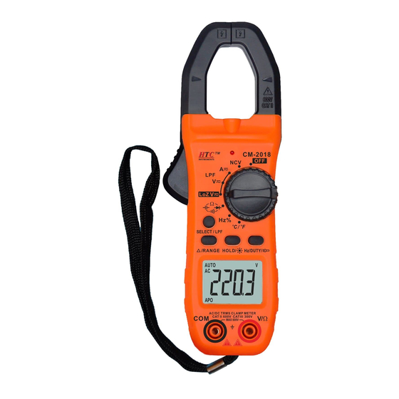
CM-2018 Digital AC/DC Clamp Meter Manual
This product is a precision instrument, be sure to read this "Instruction Manual" carefully before
use, so as not to cause damage and injury to you due to misuse.
1 . Summary
The meter is a stable performance, high reliability 3 5/6 digital AC/DC clamp meter, the meter
adopts 14mm word height LCD display, clear readings.
It can be used to measure DC voltage, AC voltage, DC current, AC current, variable frequency
voltage and current, LoZ (low impedance input) false voltage test, resistance, capacitance,
frequency, temperature, diode, continuity test and non-contact AC voltage detection. It is designed
with clamp jaw lightning function, backlight display, unit symbol display, data hold,
automatic/manual range conversion, automatic power off and alarm function. The whole machine
adopts a microprocessor capable of directly driving LCD and double-integral A/D conversion IC, a
digital display driver providing high resolution and high accuracy. The meter is fully functional,
highly accurate in measurement and easy to use, and is an ideal tool for laboratories, factories, radio
enthusiasts and families.
2 . Security guidelines
The meter complies with IEC1010-1 (EN61010-1) pollution2, CAT.III 600V and UL3111-1
standards. Please read this manual carefully before use.
2-1. Electrical symbols
"
"CAUTION: Refer to instructions before use. "
"Low voltage symbol. "
Danger of electric shock." "Double insulation.
2-2. Safety instructions and precautions for use
2-2-1. Read this manual before use, and operate in accordance with the requirements specified in the
manual to avoid accidents that endanger personal safety and damage the instrument!
2-2-2. Before opening the case, please disconnect the input signal and remove the test lead, in order
to avoid electric shock or damage to the meter, no water should leak into the case.
2-2-3. Do not use this meter for test work when the housing is not installed or its fixing screws are
not tightened.
2-2-4. Do not input the value higher than the limit at every range during measurement.
2-2-5. In the resistance range terminal, it is prohibited to access the voltage value.
2-2-6. Do not use the LPF low-pass filter option to verify the presence of dangerous voltages, which
may be present in excess of the indicated value. The voltage must be measured without the filter
connected to detect the presence of dangerous voltages.
2-2-7. Do not use LoZ mode to measure voltages in circuits that may be damaged by the low
impedance (300 kΩ) of this mode.
2-2-8. The power switch should be set to OFF after use.
2-2-9. For long-term storage, please remove the battery to avoid damage to the internal components
by battery leakage.
2-2-10. A voltage higher than 60V DC or 30V AC RMS will produce a serious risk of electric shock.
2-2-11. Be especially careful when clamping uninsulated conductors or busbars, accidental contact
with conductors can cause electric shock.
3.Integrated specification
3-1. General Characteristics
3-1-1. display mode: LCD liquid crystal display.
3-1-2. Maximum display: 6000 (3 5/6) digit automatic polarity display.
3-1-3. Maximum jaw opening: 28mm.
3-1-4. Over-range display: "OL" is displayed in the highest position.
3-1-5. Hold: Data hold.
3-1-6. Relative value measurement.
3-1-7. Sampling rate: 3 times/second.
3-1-8. Battery low voltage display: "
" s y m b o l a p p e a r s .
3-1-9. Continuity test: buzzer sounds when it is less than 50Ω.
3-1-10. Automatic range or manual range.
3-1-11. Automatic power off.
3-1-12. Power consumption: about 3mA.
3-1-13. Power source: two 1 . 5 V b a t t e r i e s ( " A A A " 7 # b a t t e r i e s ) .
3-1-14. Working environment: (0~40)℃, relative humidity<70%RH.
3-1-15. External dimensions: 1 8 5 m m × 6 5 m m × 3 2 m m ( L × W × H ) .
3-1-16. Weight: about 200g (including battery).
3-1-17. Accessories: user manual, a certificate of conformity,test leads, temperature sensor TP01
banana probe, handbag, gift box, two 1.5V batteries.
3-2. Technical specifications
3-2-1. Accuracy: ± (a% reading + word count), guaranteed for 1 year. ambient temperature (23±5)
°C, relative humidity <70%.
3-2-2. Temperature coefficient: When the temperature is <18℃ or >28℃, the additional
temperature coefficient error is 0.1 × t h e specified accuracy/℃.
3-2-3. DC Voltage
Measurement range
Accuracy
600mV
± (1.0% reading + 5)
6V
60V
± (0.5% of reading + 5)
600V
LoZ 0V-600V
± (2.0% reading + 10)
Input impedance: mV range > 40MΩ. other ranges input impedance is 10MΩ. LoZ V is 300kΩ. mV
range open circuit will have unstable digital display can be stable after connected to the load < ±3
words).
Maximum input voltage ±600V, ≥610V with alarm sound. LCD display "OL" when input >610V.
3- 2- 4. AC Voltage (A C V True RMS)
Measurement range
6V
60V
600V
LPF 0V-600V
LoZ 0V-600V
Input impedance: 10MΩ, LoZ V is 300kΩ. Accuracy guarantee range: 5~100% range, short circuit
allows less than 10 words of remaining reading.
Sine wave true RMS value is displayed. Frequency response: 40Hz~1kHz for the 600V range,
40Hz~2kHz for the rest of the range.
Maximum input voltage 600Vrms, ≥610V with alarm sound. LCD display "OL" when input
>610V.
3-2-5. DC Current
Measurement range
60A
600A
"WARNING!
800A
Overload protection: 1000A (input time not exceeding 60 seconds)
Note: Clear to zero before measurement. The measured current conductor should be placed through
the middle of the clamp jaw.
3-2-6. AC Current (True RMS)
Measurement range
60A
600A
800A
Frequency response: 40Hz- 1kHz for sine wave and triangle wave. 40Hz-200Hz for others.
Overload protection: 1000A (input time not exceeding 60 seconds)
Note: The measured current conductor should be placed through the middle of the clamp jaw.
3-2-7. Resistance (Ω)
Measurement range
600Ω
6 k Ω
60kΩ
600kΩ
6 MΩ
60MΩ
Open circuit voltage: 500mV.
Overload protection: 250 V rms.
Warning: Input of voltage values in this range is prohibited!
3-2-8. Capacitance (C)
Measurement range
6nF
60nF
600nF
6uF
60uF
600uF
6mF
60mF
Overload protection: 250V rms.
Warning: Input of voltage values in this range is prohibited!
3-2-9. Frequency: (F)
Measurement range
10Hz~10MHz
Input sensitivity: >0.7V. Overload protection: 250V rms
Resolving power
3-2-10. Temperature
0.1mV
Measurement range
0.001V
(-40~1000) °C
0.01V
0.1V
(-40~1832) ℉
0.1V
Sensor: K-type banana plug (NiCr-NiSi).
Warning: Input of voltage values in this range is prohibited!
Accuracy
Resolving power
0.001V
± (0.8% of reading + 5)
0.01V
0.1V
± (4.0% reading + 5)
0.1V
± (2.0% reading + 10)
0.1V
Accuracy
Resolving power
10mA
± (1.5% of reading + 5)
100mA
1A
Accuracy
Resolving power
10mA
± (1.5% of reading +5)
100mA
1A
Accuracy
Resolving power
± (0.8% of reading +5)
0.1Ω
1Ω
± (0.8% of reading +1)
10Ω
100Ω
1kΩ
± (1.0% of reading +5)
10kΩ
Accuracy
Resolving power
1pF
± (5.0% of reading +10)
10pF
100pF
1nF
± (2.5% of reading +5)
10nF
100nF
± (5.0% of reading +10)
1uF
10uF
Resolving power
Accuracy
± (0.5% of reading +4)
0.001Hz~1kHz
Accuracy
Resolving power
<400°C: ± (1.0% of reading +5)
1 ℃
≥400°C: ± (1.5% of reading +15)
<750°F: ± (1.0% of reading + 5)
1°F
≥750°F: ± (1. 5% of reading + 15)
3-2-11. Diode – Continuity Test
Measurement
Display value
range
Diode forward voltage drop.
Forward DC current 0.8mA, open circuit
voltage about 2.2V.
The buzzer sounds long when the resistance
Open circuit voltage is about 2V, press
value of two points is less than 50Ω.
"SELECT/LPF" function to switch.
Overload protection: 250V rms.
Warning: Input of voltage values in this range is prohibited!
4. OPERATION
4-1. Panel Description
(1)Clamp: 0A to 800A DC AC current and non-contact voltage detecting.
(2)Plier head trigger: pulling the plier head trigger can open the plier head.
(3)Hand protection: a safety design to protect the user's hands from
touching the dangerous area.
(4)Clamp light: open the clamp lightning function to illuminate the measured area in the dark to
avoid danger.
(5)NCV indicator: detect the existence of the high voltage in the surrounding area to prevent the
risk of electric shock.
(6)Knob switch: Used to switch and select the function and range, turn on/off the meter.
Function
Description
Non-contact AC voltage detection.
NCV
DC current and AC current measurement, press "SELECT/LPF" to switch the
measurement.
AC/DC voltage measurement. Long press "SELECT/LPF" key to switch low-pass
filter measurement. Press Hz/DUTY to toggle frequency/duty cycle measurement to
accommodate high frequency and voltage amplitude measurement.
Low impedance voltage measurement to determine if there is a spurious voltage in the
LoZ
circuit.
Press "SELECT/LPF" to select resistance measurement, diode, continuity
measurement, and capacitance measurement cycle switching.
Frequency measurement, press Hz/DUTY key to switch the frequency/duty cycle
Hz %
measurement, adapt to frequency voltage amplitude below 10V signal
measurement.
For temperature measurement, press the "SELECT/LPF" key to switch between °C
℃/℉
or °F.
(7)Function Keys
SELECT/LPF keys.
1) This is key fo selecting function, base on a working principle of trigger action. Short press this
key to choose measurement modes: choose DC or AC in
state. choose the Ω /
in
state. choose °C or °F in temperature measurement state. switch frequency/duty cycle
measurement in AC voltage measurement state.
2) In ACV/ACA mode, press SELECT/LPF to enter LPF low-pass filter.
An internal specific filtering circuit to filter out high-
frequency beyond 1kHz interference signals to ensure the accuracy. It can be applied to the
occasions with variable frequency voltage and current.
3) The meter will be auto power off when there is no operation within 15minutes, then it will enter
the sleeping mode, the buzzer will sound 5 times of alarm reminder within 1 minute before auto
power off, please press this key to turn on the meter if you need to restart the device.
4) Press this key and put it on Hold and then turn on the Power to awake the meter from sleeping
mode, and then auto power off function will be canceled.
REL/ RANGE keys.
1) In
and
measurement is "REL" function, press this key to clear the reading to zero and
enter the relative value measurement, the display appears "REL" symbol, press again to exit the
relative value measurement. (In
and
measurement, the display does not return to zero
before measurement, you need to press this key to make the display to "0" before measurement.)
2) In the voltage and resistance measurement is "RANGE" function, press this key to select the
automatic range or manual range working mode. The instrument starts in the auto range state,
displaying the "AUTO" symbol, press this function to change to manual range, press once to
increase one gear, cycle from low to high. Press this key continuously for more than 2 seconds to
return to the automatic range state.
HOLD/
key.
It is a key for Data Hold function to keep the display reading, based on a working principle of
trigger action, short press this key to lock the display value on
screen, kept unchanged, and then press other keys HOLD
function is canceled. Press this key for more than 2 seconds to
turn on the display Backlight function, press this key again for
2 seconds to turn off the backlight, if you do not press this key
after opening it will automatically go out after 30 seconds.
Hz/DUTY/
key.
1) When measuring AC voltage (current), follow this function
to switch the frequency/duty cycle/voltage (current), and
switch the frequency/duty cycle (1-99%) when measuring
frequency.
2) Lighting control key, press for more than 2 seconds lighting on, and then press for more than 2
seconds, the lighting will turn off.
Test conditions
/
/
Advertisement

Related Manuals for HTC CM-2018


Summary of Contents for HTC CM-2018
- Page 1 3- 2- 4. AC Voltage (A C V True RMS) 3-2-11. Diode – Continuity Test CM-2018 Digital AC/DC Clamp Meter Manual Measurement Display value Test conditions Measurement range Accuracy Resolving power This product is a precision instrument, be sure to read this "Instruction Manual" carefully before range 0.001V...
- Page 2 (8)Display: Shows the value and unit measured by the meter. (3)Press and hold the trigger to open the clamp jaw, use the forceps to clamp the (1)It is strictly forbidden to input voltage or current signals in the measuring capacity range. conductor to be measured, and then slowly release the trigger until the (2)Before each test, if the display has readings, you must press the "REL"...