Advertisement
Quick Links
Torque Sensor
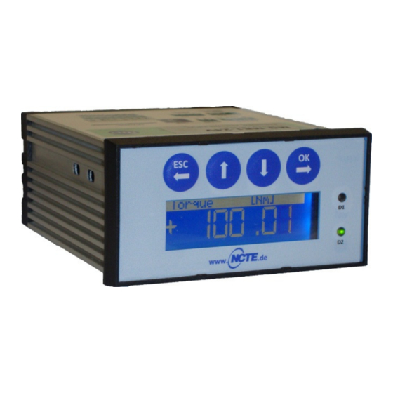
Read Out Unit
Quick Start Guide
1. Short description
This document is a short guide for connecting and using the read out unit together with standard NCTE torque
sensor families.
2. Basic connection diagram
USB
Read Out Unit
Pin
Label
3
V+
2
GND
Read Out Unit
Pin
Label
14
a. GND
15
ENCB
16
ENCA
17
AIN
20
GND
21
+12V
Revision B
Modifications reserved. All details describe our products in general form only. They are not to be
understood as a guarantee of quality or durability and do not constitute any liability whatsoever.
Sept. 30, 2013
Contents:
1. Short description
2. Basic connection diagram
3. Basic configuration (using MG-ME1 PC-Software)
4. Measurement data displays
5. Setting up data acquisition (PC)
DC Power Supply
Description
Supply Voltage +
(+15 .. 30 VDC)
Supply Voltage –
(GND)
Sensor Series 2000
(Connector: Binder Series 712 )
Pin
Color
Description
-
-
-
-
-
-
-
-
-
Signal Output
2
Brown
V
out
3
Black
Ground
Supply voltage
1
White
V
CC
• On Windows the read out unit is installed as HID
and does not require special drivers.
• The MG-ME1 PC Software runs as is and needs
no further installation. It can be downloaded at
www.ncte.com.
Power
Sensor
Sensor Series 3000 / 4000
(Connector: Binder Series
423/723/425 )
Pin
Color
Description
D
Yellow
Analog GND
Red
H
Angle Ch B
Pink
F
Angle Ch A
C
Green
Analog Out
Brown
B
Ground GND
Supply voltage
White
S
V
CC
www.ncte.de
Sensor Series 7000
(Connector: Binder Series M16
Connector IP67)
Pin
Color
Description
Grey
E
Analog GND
Angle Channel
Yellow
D
B
Angle Channel
Green
C
A
Analog voltage
F
Pink
signal output
Blue
G
Ground GND
Supply voltage
Red
H
V
CC
Page 1
Advertisement

Summary of Contents for NCTE Read Out Unit
- Page 1 4. Measurement data displays 5. Setting up data acquisition (PC) 1. Short description This document is a short guide for connecting and using the read out unit together with standard NCTE torque sensor families. 2. Basic connection diagram • On Windows the read out unit is installed as HID and does not require special drivers.
- Page 2 Torque Sensor www.ncte.de Read Out Unit Quick Start Guide 3. Basic configuration (using MG-ME1 PC Software) Torque Input: Select decimal precision for torque display and data recording and press the [Save] button. While sensor is unloaded (zero torque) press the [Set zero] button.
- Page 3 Torque Sensor www.ncte.de Read Out Unit Quick Start Guide 4. Measurement data displays The PC Software has two tabs which can display live measurement data • “Measurement” tab: numerical displays • “Chart” tab: data plot with various editable properties, print option and image export.
