
Related Manuals for LevelOne IFE-0501


Summary of Contents for LevelOne IFE-0501
- Page 1 LevelOne IFE-0501/IFE-0502 4-Port PoE + 1-Port SC Industrial Fast Ethernet Switch User Manual Ver. 1.0.0-0711...
-
Page 2: Fcc Warning
FCC Warning This Equipment has been tested and found to comply with the limits for a Class-A digital device, pursuant to Part 15 of the FCC rules. These limits are designed to provide reasonable protection against harmful interference in a residential installation. This equipment generates, uses, and can radiate radio frequency energy. -
Page 3: Table Of Contents
INTRODUCTION...4 ... 4 EATURES ... 5 ACKAGE ONTENTS HARDWARE DESCRIPTION...6 ... 6 HYSICAL IMENSION ... 6 RONT ANEL ... 7 LED I ... 8 NDICATORS ... 9 ORTS ...11 ABLING IRING THE OWER NPUTS IRING THE AULT LARM MOUNTING INSTALLATION ...14 DIN-R ... -
Page 4: Introduction
Introduction The 4-Port PoE + 1-Port SC Industrial Fast Ethernet Switch is a cost-effective solution and meets the high reliability requirements demanded by industrial applications. Using fiber port can extend the connection distance that increases the network elasticity and performance. In addition, the industrial switch provides the PoE function for kinds of Powered Devices to receive power as well as data over the RJ-45 cable. -
Page 5: Package Contents
Pluggable Terminal Block (attached on the switch) 2 wall mount plates with screws One DIN-Rail (attached on the switch) Compare the contents of the industrial switch with the standard checklist above. If any item is damaged or missing, please contact the local dealer for service. -
Page 6: Hardware Description
In this paragraph, the Industrial switch’s hardware spec, port, cabling information, and wiring installation will be described. Physical Dimension 4-Port PoE + 1-Port SC Industrial Fast Ethernet Switch dimension (W x D x H) is 30mm x 95mm x 140mm Front Panel... -
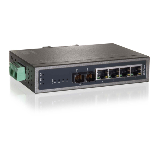
Page 7: Top View
Front Panel of the IFE-0502 Industrial Fast Ethernet Switch Top View The top view of the 4-Port PoE + 1-Port SC Industrial Fast Ethernet Switch has one terminal block connector of two DC power inputs. Top View of the IFE-0501/IFE-0502 Industrial Fast Ethernet Switch... -
Page 8: Led Indicators
LED Indicators The diagnostic LEDs located on the front panel of the industrial switch provide real-time information of system and optional status. The following table provides the description of the LED status and their meanings for the switch. Color Green... -
Page 9: Ports
RJ-45 ports The UTP (RJ-45) Fast Ethernet ports will auto-sense for 10Base-T or 100Base-TX connections. Auto MDI/MDIX means that the switch can connect to another switch or workstation without changing straight through or crossover cabling. See the below figures for straight through and crossover cable schematic. - Page 10 Fiber Port The fiber port of SC type connector can work in multi-mode (2Km) or single-mode (30Km). When you connect the fiber port to another one, please follow the figure below to connect accordingly. Wrong connection will cause the port cannot work normally.
-
Page 11: Cabling
(STP) cable. The cable must comply with the IEEE 802.3u 100Base TX standard for Category 5. The cable between the converter and the link partner (switch, hub, workstation, etc.) must be less than 100 meters (328 ft.) long. -
Page 12: Wiring The Power Inputs
Wiring the Power Inputs Please follow the steps below to insert the power wire. Insert the positive and negative wires into the V+ and V- contacts on the terminal block connector. Tighten the wire-clamp screws for preventing the wires from loosing. -
Page 13: Wiring The Fault Alarm Contact
Wiring the Fault Alarm Contact The fault alarm contact is in the middle of terminal block connector as the picture shows below. When the wires are inserted into ports 3 and 4, they automatically detect the fault status in the event of a power failure by forming an open circuit. An example for the fault alarm contact is shown as below: Insert the wires into the fault alarm contact. -
Page 14: Mounting Installation
Mounting Installation DIN-Rail Mounting The DIN-Rail is screwed on the industrial switch when out of factory. If the DIN-Rail is not screwed on the industrial switch, please see the following pictures to screw the DIN-Rail on the switch. Follow the steps below to hang the industrial switch. - Page 15 Then, lightly push the DIN-Rail into the track. Check if the DIN-Rail is tightened on the track or not. To remove the industrial switch from the track, reverse steps above.
-
Page 16: Wall Mount Plate Mounting
Wall Mount Plate Mounting Follow the steps below to mount the industrial switch with wall mount plate. Remove the DIN-Rail from the industrial switch; loose the screws to remove the DIN-Rail. Place the wall mount plate on the rear panel of the industrial switch. -
Page 17: Hardware Installation
Installation Steps Unpack the Industrial switch packing. Check if the DIN-Rail is screwed on the Industrial switch or not. If the DIN-Rail is not screwed on the Industrial switch, please refer to DIN-Rail Mounting section for DIN-Rail installation. If user want to wall mount the Industrial switch, then please refer to Wall Mount Plate Mounting section for wall mount plate installation. -
Page 18: Network Application
Network Application This segment provides the sample to help user have more actual idea of industrial switch application. For a sample application of the industrial switch, see the figure below. -
Page 19: Troubleshooting
If you still cannot resolve the problem, contact the local dealer for assistance. If the Industrial switch LED indicators are normal and the connected cables are correct but the packets still cannot transmit. Please check your system’s Ethernet... -
Page 20: Technical Specification
Technical Specification The IFE-0501/IFE-0502 4-Port PoE + 1-Port SC Industrial Fast Ethernet Switch technical specifications are shown as below. IFE-0501 4-Port PoE + 1-Port Multi-mode SC Industrial Fast Ethernet Switch IFE-0502 4-Port PoE + 1-Port Single-mode SC Industrial Fast Ethernet Switch IEEE 802.3 10Base-T Ethernet... - Page 21 Distance: Multi mode: 50/125μm ~ 62.5/125μm Single mode: 9/125μm Optical cable Available distance: 2km (multi-mode)/30km (single-mode) Wavelength: 1310nm (Multi-mode/Single-mode) Redundant power DC 48V with removable terminal block Power Supply 12VDC (without PoE); 48VDC (Full load with PoE) Power 4.6Watts (without PoE); 58Watts (Full load with PoE) Consumption DIN rail kit for DIN-type cabinet install and wall-mount ear Installation...