Advertisement
Quick Links
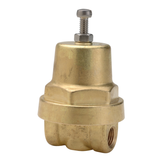
CASH VALVE TYPE FRM CRYOGENIC BACK PRESSURE OR ECONOMIZER VALVE
INSTALLATION, MAINTENANCE AND REPAIR PARTS INFORMATION
Before installation, these instructions must be read carefully and understood.
DESCRIPTION
The Type FRM is designed to function as a Back
Pressure or Economizer valve in Cryogenic
Circuits. The Back Pressure Function is to
open at a preset pressure and relieve inlet
pressure to the discharge side into a lower
pressure. The Economizer function is to open
at a preset pressure, above the Pressure Build
set pressure, and continue to open as gas
head pressure from heat leak builds during
non-use periods of the system. The Economizer
by-passes gas head pressure directly to the
Final Line circuit, when system draw resumes,
to draw down the excess pressure rapidly
and recloses before the Pressure Build
regulator opens. The Type FRM valve is small
and compact, yet is highly efficient making it
suitable for numerous applications that call for
a small, accurate back pressure regulator. The
Type FRM incorporates a "floating ring" design
that provides for smooth even pressure control.
Emerson.com/FinalControl
SPECIFICATION DATA
Service: Cryogenic liquids and gases. Well
suited for use in the Economizer circuit as a
heat leak economizer valve in systems having
relatively low flows.
Sizes: ¼" or ⅜"
Connections: Threaded female inlet and outlet
connections
Body: Bronze
Maximum Temperature: +150°F (66°C) to
-320°F (-196°C)
Maximum Set Pressure: 600 psi (41 bar)
Shipping Weight: 1⅛ lbs.
Capacity: For specific capacity information,
consult the factory.
CONSTRUCTION
Forged Bronze body; Stainless Steel seat
disc, seat ring and pressure spring; Phosphor
Bronze diaphragms with Teflon diaphragm
gaskets.
All parts commercially cleaned for cryogenic
service.
© 2019 Emerson. All rights reserved.
GENERAL INSTALLATION INSTRUCTIONS
Type FRM valves are available with three
different body styles for pipe connections to
enable it to be adapted to most any system:
side inlet-side outlet, side inlet-bottom outlet, 2
opposite side inlets-bottom outlet.
When installing the valve, connect the
supply line to the inlet connection. The outlet
connection should be connected to the bypass
or final vaporizer line. Valves with 2 opposite
side inlets and a bottom outlet may be installed
as an angle valve with one inlet plugged, or
alternitavely used as an in-line valve with
regulated pressure on both the inlet and
process sides of the valve.
It is recommended that Type FRM valves be
installed in the horizontal position with the
spring chamber upright. For ease of operation
and maintenance, it is suggested that manual
shut-off valves be installed upstream and
downstream from the valve. Use a compatible
sealant on the male pipe threads and do not
overtighten the valve connections.
Other considerations in making a good
installation are:
1. The valve should be sized properly for the
service conditions.
2. Type FRM valves are diaphragm operated
valves designed for the continuous
operating pressure control of a system. All
Type FRM valves are fitted with a diaphragm
travel stop to prevent the diaphragms from
extending beyond their limit; however,
should a diaphragm fail, the valve will fail in
the closed position. As a safeguard, it may
be desirable to protect the system against
damaging high pressures by a safety relief
valve or some other type of safety device.
VCIOM-13802-EN 19/08
Advertisement

Related Manuals for Emerson CASH VALVE FRM


Summary of Contents for Emerson CASH VALVE FRM
- Page 1 Type FRM incorporates a "floating ring" design disc, seat ring and pressure spring; Phosphor that provides for smooth even pressure control. Bronze diaphragms with Teflon diaphragm gaskets. All parts commercially cleaned for cryogenic service. Emerson.com/FinalControl VCIOM-13802-EN 19/08 © 2019 Emerson. All rights reserved.
- Page 2 CASH VALVE TYPE FRM CRYOGENIC BACK PRESSURE OR ECONOMIZER VALVE INSTALLATION, MAINTENANCE AND REPAIR PARTS INFORMATION OPERATING INSTRUCTIONS 4. The Diaphragm assembly, consisting of the pressure plate nut (8), lock washer (9), Adjusting the Back Pressure diaphragm pressure plate (10), diaphragms The regulator's back pressure setting is (11), seat disc gasket (13) and seat disc adjusted by turning the adjusting screw (1) at...
- Page 3 Responsibility for proper selection, use, and maintenance of any product remains solely with the purchaser and end user. Cash Valve is a mark owned by one of the companies in the Emerson Automation Solutions business unit of Emerson Electric Co. Emerson Automation Solutions, Emerson and the Emerson logo are trademarks and service marks of Emerson Electric Co.