Advertisement
Quick Links
Supplementary Service Station Manual
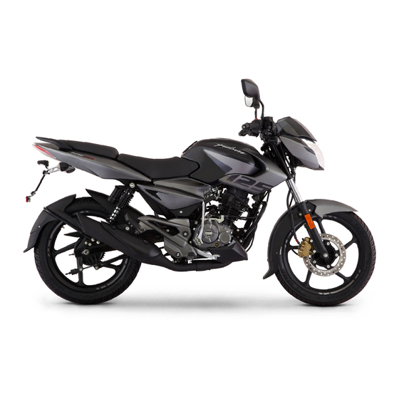
Pulsar 125 BS VI
Model :
Pulsar 125 Disc-Drum, Single seat: 00DH40ZZ
Pulsar 125 Drum-Drum, Single seat : 00DH36ZZ (Same as existing)
Pulsar 125 Disc-Drum, Split seat : 00DH34ZZ (Same as existing)
Pulsar 125 Drum-Drum, Split seat : 00DH38ZZ (Same as existing)
• Specification Information
- Technical Specifications
- Preventive Maintenance
- PDI Check Sheet
- Fuel Tank Cap &
• Part Identification
• Wiring Harness Routing
• Circuit Diagram
1
Chart
Speedometer Related
Information
- Side Stand Switch
Interlocking
Advertisement

Related Manuals for Bajaj pulsar 125


Summary of Contents for Bajaj pulsar 125
- Page 1 • Specification Information Model : Pulsar 125 Disc-Drum, Single seat: 00DH40ZZ - Technical Specifications Pulsar 125 Drum-Drum, Single seat : 00DH36ZZ (Same as existing) - Preventive Maintenance Chart Pulsar 125 Disc-Drum, Split seat : 00DH34ZZ (Same as existing) - PDI Check Sheet Pulsar 125 Drum-Drum, Split seat : 00DH38ZZ (Same as existing) - Fuel Tank Cap &...
-
Page 2: Specification Information
Technical Specification All specification are same as existing Pulsar 125 Disc-Drum, Single seat: 00DH32ZZ Pulsar 125 Drum-Drum, Single seat : 00DH36ZZ Pulsar 125 Disc-Drum, Split seat : 00DH34ZZ Pulsar 125 Drum-Drum, Split seat : 00DH38ZZ Refer supplementary SSM available on essm. - Page 3 SPECIFICATION INFORMATION Speedometer related information : 1. Side Stand Indicator: It glows when Side stand is down & 8. Trip Meter Reset Button: Both trip meters can be r e s e t t o igntion switch is ‘ON’ and kill switch in ‘Engine ON’ position. zero by pressing the button.
-
Page 4: Part Identification
PART IDENTIFICATION For Pulsar 125 Disc-Drum, Single seat: 00DH40ZZ, NOTE : For part numbers, always refer spare parts catalogue available on e-ssm. Model Pulsar 125 (00DH32ZZ) Pulsar 125 (00DH40ZZ) DC Flasher / Light Control Module Part Name Photograph Part Number... - Page 5 PART IDENTIFICATION For Pulsar 125 Drum-Drum, Single seat : 00DH36ZZ (Same as existing) NOTE : For part numbers, always refer spare parts catalogue available on e-ssm. Model Pulsar 125 (00DH36ZZ) Existing Pulsar 125 (00DH36ZZ) New Cable guide & Nail cable guide...
- Page 6 Model Pulsar 125 (00DH36ZZ) Existing Pulsar 125 (00DH36ZZ) New Holder Step Rider LH Part Name Photograph Part Number DH161825 DH161719 Design is different than Pulsar 125 (00DH36ZZ) Description Existing Wiring Harness Part Name Part Number DH201162 DH201177 Description • Speedometer branch with two couplers : •...
- Page 7 3 mm allen key. This screw set Socket is Locking shaft Rocker arm as shown in Photograph. Model Pulsar 125 (00DH36ZZ) Existing Pulsar 125 (00DH36ZZ) New Cover Cylinder Head (Sub part of Kit Cover Head & Cylinder Head) Part Name...
- Page 8 Part Name Camshaft Assembly Photograph Part Number PD511256 DH102546 • Cam lobe design is different than Pulsar 125 • NA Description • Identification : With punch marks (00DH36ZZ) Existing • Identification : Without punch marks Cam Sprocket / Crankshaft assembly / Cam chain...
- Page 9 PART IDENTIFICATION Model Pulsar 125 (00DH36ZZ) Existing Pulsar 125 (00DH36ZZ) New Assembly Silencer Part Name Part Number DH102528 DH103809 & DH102528 Description For DH103809 : Catalytic converter cell density more as compared to DH102528.After consumption of DH102528, DH103809 will be implemented...
- Page 10 PART IDENTIFICATION Pulsar 125 Disc-Drum, Split seat : 00DH34ZZ (Same as existing) NOTE : For part numbers, always refer spare parts catalogue available on e-ssm. Model Pulsar 125 (00DH34ZZ) Existing Pulsar 125 (00DH34ZZ) New DC Flasher / Light Control Module...
- Page 11 PART IDENTIFICATION Model Pulsar 125 (00DH34ZZ) Existing Pulsar 125 (00DH34ZZ) New Holder Step Rider LH Part Name Photograph Part Number DH161825 DH161719 Design is different than Pulsar 125 (00DH34ZZ) Description Existing Service Support - M/C Service Station Manual...
- Page 12 PART IDENTIFICATION Pulsar 125 Drum-Drum, Split seat : 00DH38ZZ (Same as existing) NOTE : For part numbers, always refer spare parts catalogue available on E-SSM. Model Pulsar 125 (00DH38ZZ) Existing Pulsar 125 (00DH38ZZ) New DC Flasher / Light Control Module...
- Page 13 Pulsar 125 (00DH38ZZ) Existing Pulsar 125 (00DH38ZZ) New Holder Step Rider LH Part Name Photograph Part Number DH161825 DH161719 Design is different than Pulsar 125 (00DH34ZZ) Description With Light control module Existing Part Name Bracket Assembly Number Plate Front Photograph Part Number...
- Page 14 PART IDENTIFICATION COMMON FOR Pulsar 125 Disc-Drum, Single seat: 00DH40ZZ Pulsar 125 Drum-Drum, Single seat : 00DH36ZZ (Same as existing) Pulsar 125 Disc-Drum, Split seat : 00DH34ZZ (Same as existing) Pulsar 125 Drum-Drum, Split seat : 00DH38ZZ (Same as existing) NOTE : For part numbers, always refer spare parts catalogue available on e-ssm.
- Page 15 PART IDENTIFICATION Model Pulsar 125 Existing (All variants) Pulsar 125 New (All variants) ECU EMS Assembly Part Name Part Number Refer SPC Refer SPC Software is different than Pulsar 125 Existing Description (All variants) Service Support - M/C Service Station Manual...
- Page 16 WIRING HARNESS ROUTING Pulsar 125 Disc Drum Single seat (DH40) • Route the wiring harness as shown in photograph. Service Support - M/C Service Station Manual...
- Page 17 WIRING HARNESS ROUTING • Route the wiring harness as shown in photograph. • Route the wiring harness as shown in photograph. Service Support - M/C Service Station Manual...
- Page 18 WIRING HARNESS ROUTING • Route the wiring harness as shown in photograph • Route the wiring harness as shown in photograph Service Support - M/C Service Station Manual...
- Page 19 WIRING HARNESS ROUTING • Route the wiring harness as shown in photograph. • Route the wiring harness as shown in photograph. Service Support - M/C Service Station Manual...
- Page 20 WIRING HARNESS ROUTING • Route the wiring harness as shown in photograph • Route the wiring harness as shown in photograph Service Support - M/C Service Station Manual...
- Page 21 WIRING HARNESS ROUTING • Route the wiring harness as shown in photograph • Route the wiring harness as shown in photograph Service Support - M/C Service Station Manual...
- Page 22 WIRING HARNESS ROUTING • Route the wiring harness as shown in photograph Service Support - M/C Service Station Manual...
- Page 23 WIRING HARNESS ROUTING •Pulsar 125 Disc Drum Split seat (DH34) • Route the wiring harness as shown in photograph...
- Page 24 WIRING HARNESS ROUTING • Route the wiring harness as shown in photograph. • Route the wiring harness as shown in photograph Service Support - M/C Service Station Manual...
- Page 25 WIRING HARNESS ROUTING • Route the wiring harness as shown in photograph • Route the wiring harness as shown in photograph Service Support - M/C Service Station Manual...
- Page 26 WIRING HARNESS ROUTING • Route the wiring harness as shown in photograph. • Route the wiring harness as shown in photograph Service Support - M/C Service Station Manual...
- Page 27 WIRING HARNESS ROUTING • Route the wiring harness as shown in photograph. • Route the wiring harness as shown in photograph. Service Support - M/C Service Station Manual...
- Page 28 WIRING HARNESS ROUTING • Route the wiring harness as shown in photograph. • Route the wiring harness as shown in photograph Service Support - M/C Service Station Manual...
- Page 29 WIRING HARNESS ROUTING • Route the wiring harness as shown in photograph. Service Support - M/C Service Station Manual...
- Page 30 WIRING HARNESS ROUTING Pulsar 125 Drum Drum Single seat (DH36) • Route the wiring harness as shown in photograph. Service Support - M/C Service Station Manual...
- Page 31 WIRING HARNESS ROUTING • Route the wiring harness as shown in photograph • Route the wiring harness as shown in photograph Service Support - M/C Service Station Manual...
- Page 32 WIRING HARNESS ROUTING • Route the wiring harness as shown in photograph. • Route the wiring harness as shown in photograph Service Support - M/C Service Station Manual...
- Page 33 WIRING HARNESS ROUTING • Route the wiring harness as shown in photograph • Route the wiring harness as shown in photograph Service Support - M/C Service Station Manual...
- Page 34 WIRING HARNESS ROUTING • Route the wiring harness as shown in photograph • Route the wiring harness as shown in photograph. Service Support - M/C Service Station Manual...
- Page 35 WIRING HARNESS ROUTING • Route the wiring harness as shown in photograph. • Route the wiring harness as shown in photograph Service Support - M/C Service Station Manual...
- Page 36 WIRING HARNESS ROUTING • Route the wiring harness as shown in photograph. Service Support - M/C Service Station Manual...
- Page 37 WIRING HARNESS ROUTING Pulsar 125 Drum Drum Split seat (DH38) • Route the wiring harness as shown in photograph. Service Support - M/C Service Station Manual...
- Page 38 WIRING HARNESS ROUTING • Route the wiring harness as shown in photograph. • Route the wiring harness as shown in photograph. Service Support - M/C Service Station Manual...
- Page 39 WIRING HARNESS ROUTING • Route the wiring harness as shown in photograph. • Route the wiring harness as shown in photograph. Service Support - M/C Service Station Manual...
- Page 40 WIRING HARNESS ROUTING • Route the wiring harness as shown in photograph • Route the wiring harness as shown in photograph Service Support - M/C Service Station Manual...
- Page 41 WIRING HARNESS ROUTING • Route the wiring harness as shown in photograph. • Route the wiring harness as shown in photograph Service Support - M/C Service Station Manual...
- Page 42 WIRING HARNESS ROUTING • Route the wiring harness as shown in photograph • Route the wiring harness as shown in photograph Service Support - M/C Service Station Manual...
- Page 43 WIRING HARNESS ROUTING • Route the wiring harness as shown in photograph Service Support - M/C Service Station Manual...
-
Page 44: Electric Circuit Diagram
ELECTRIC CIRCUIT DIAGRAM Speedometer Pin Details SPEED SENSOR SUPPLY IGNITION SUPLY HIGH BEAM Gr/R Gr/R KILL SWITCH SUPPLY FUEL UNIT SPEED SENSOR INPUT RIGHT TURN INDICATOR LEFT TURN INDICATOR GROUND GROUND BACKLIGHT CAN HIGH CAN LOW BATTERY Service Support - M/C Service Station Manual... - Page 45 ELECTRIC CIRCUIT DIAGRAM Control Unit Pin Details IGNITION (HT COIL) I AIR SOLENOID INTERMEDIATE RELAY HEADLAMP RELAY AUTO CHOKE SOLENOID CAN HIGH CAN LOW 8 ENGINE TEMP SENSOR KILL SWITCH SUPLLY (KEP) 10 IGNITION (HT COIL) II 11 V BATTERY 12 XDRG 13 XDRP 14 SIDE STAND SWITCH...
-
Page 46: Battery Charging Circuit
ELECTRIC CIRCUIT DIAGRAM BATTERY CHARGING CIRCUIT FUSE BOX Service Support - M/C Service Station Manual... - Page 47 ELECTRIC CIRCUIT DIAGRAM STARTER MOTOR CUM SIDE STAND CIRCUIT FUSE BOX Service Support - M/C Service Station Manual...
-
Page 48: Ignition Circuit
ELECTRIC CIRCUIT DIAGRAM IGNITION CIRCUIT FUSE BOX Service Support - M/C Service Station Manual... -
Page 49: Fuel Meter Circuit
ELECTRIC CIRCUIT DIAGRAM FUEL METER CIRCUIT FUSE BOX Service Support - M/C Service Station Manual... - Page 50 ELECTRIC CIRCUIT DIAGRAM CAN / MIL CIRCUIT FUSE BOX Service Support - M/C Service Station Manual...
- Page 51 ELECTRIC CIRCUIT DIAGRAM AIR SOLENOID VALVE CIRCUIT FUSE BOX Service Support - M/C Service Station Manual...
- Page 52 ELECTRIC CIRCUIT DIAGRAM VEHICLE SPEED INDICATION CIRCUIT FUSE BOX Service Support - M/C Service Station Manual...
- Page 53 ELECTRIC CIRCUIT DIAGRAM BRAKE LAMP CIRCUIT FUSE BOX Service Support - M/C Service Station Manual...
-
Page 54: Lighting Circuit
ELECTRIC CIRCUIT DIAGRAM LIGHTING CIRCUIT FUSE BOX Service Support - M/C Service Station Manual... - Page 55 ELECTRIC CIRCUIT DIAGRAM SIDE INDICATOR REAR INDICATOR RH REAR INDICATOR LH FUSE BOX FRONT INDICATOR RH Service Support - M/C Service Station Manual...