Table of Contents
Advertisement
Quick Links
Advertisement
Table of Contents

Summary of Contents for TBA KM5S-LCD
- Page 1 USERS GUIDE KM5S–LCD...
-
Page 2: Table Of Contents
ONTENTS ABOUT THE USER MANUAL APPEARANCE AND SIZE ATERIAL AND OLOUR FUNCTION SUMMARY AND BUTTON DEFINITION UNCTION SUMMARY ONITOR UTTON DEFINITION OPERATION CAUTIONS INSTALLATION INSTRUCTION NORMAL OPERATION OWER ON ISPLAY INTERFACE USH CRUISE CONTROL URN ON OFF BACKLIGHT LEVEL SELECTION ATTERY INDICATOR... - Page 3 OTOR POWER MONITOR RROR CODE INFORMATION USER SETTING REPARATION BEFORE STARTING ENERAL SETTING RIP DISTANCE AND TRIP TIME CLEARANCE ACKLIGHT CONTRAST OWER ON PASSWORD ENABLE DISABLE OWER ON PASSWORD ENABLE OWER ON PASSWORD MODIFY ORMAL PARAMETER SETTING HEEL DIAMETER SETTING PEED LIMIT SETTING PERSONALIZED PARAMETER SETTING...
- Page 4 ROPORTION PARAMETER SETTING OF PEED SENSOR SELECTION HROTTLE DEFINITION HROTTLE NABLE ISABLE HROTTLE LEVEL ENABLE DISABLE YSTEM SETTING ELAY TIME SETTING OF BATTERY POWER AX SPEED LIMIT UTTON SETTING SPEED SETTING LOWLY START UP SETTING NTERFACE OF SLOWLY SETTING UP XIT SETTING RECOVER DEFAULT SETTING BARCODE...
- Page 5 APPENDIX 1:E TTACHED LIST RROR CODE DEFINITION 2: P TTACHED LIST ASSWORD TABLE 3:P TTACHED LIST ERSONALIZED PARAMETER SETTING ATTACHED LIST 4:POWER ASSIST TABLE ATTACHED LIST 5:SYMBOL DEFINITION...
-
Page 6: About The User Manual
About the User Manual Dear users, To ensure the best performance of your e-bike, please read through the KM5S product introduction carefully before using it. We will detail all steps including: hardware installation, setting up software and normal operation of the display. The introduction will also help you to resolve the possible confusion or malfunctions. -
Page 7: Appearance And Size
Appearance and Size Material and Colour KM5S products are made of PC plastic. This material ensures normal operation & robust mechanical performance in the temperature range of -20℃ to 60℃. Real product and dimension figure (unit: mm) -
Page 8: Function Summary And Button Definition
Function Summary and Button Definition Function summary KM5S provides a wide range of functions and indicators to fit the user’s needs. The indicator contents are as follows. ◆Battery indicator ◆Motor power ratio ◆Speed display (including running speed, max speed and average speed) ◆Trip distance and total distance ◆Time display of single trip ◆Cruise control... -
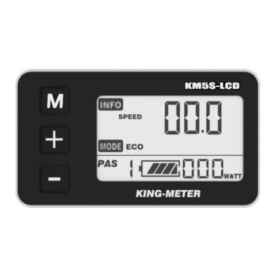
Page 9: Monitor Area
Monitor Area Monitor Area Button definition KM5S has three buttons. They are . In the following introduction, is named as “MODE”. is named as “UP” and is named as “DOWN”. Operation Cautions Take care to use safety. Don’t attempt to release the connector when the battery is powered on. - Page 10 Try to avoid hitting. Don’t remove the waterproof sticker to avoid affecting the waterproof performance. Don’t modify system parameters to avoid suboptimal performance. Take the display to be repaired when the error code appears.
-
Page 11: Installation Instruction
Installation Instruction Fix the display onto the handlebar and adjust to an appropriate visual angle. Tighten all the screws & connectors. Normal Operation Power on/off Long press MODE button (for 2 seconds) then the display & controller will. With the display on, long press MODE to turn off the power supply to the e-bike. -
Page 12: Display Interface
Display interface After starting up the display, the default display is running speed. Short press MODE to change the indicated information in sequence as follows: Running speed (Km/h) → Average speed (Km/h) → Max speed (Km/h) → Trip distance (km) → Total distance (km) → Travel time →... -
Page 13: Turn On/Off Backlight
Push cruise control 6Km/h “Push Cruise Control” function should only be used while pushing the e-bike by hand. Please don’t use this function when riding. Turn on/off backlight Hold UP for 2 seconds to turn on the backlight of the display, the headlight (if installed) will be power on at the same time. -
Page 14: Pas Level Selection
PAS level selection Short press UP/DOWN to change the output power of the motor. The power ranges from level 1 to level 5. Level 1 being the minimum power & level 5 the maximum power. The default value is level 1. PAS level Battery indicator The 5 battery bars represent the capacity of the... -
Page 15: Motor Power Monitor
Motor power monitor Motor power showed as below: Error code information If there is something wrong with the electronic control system, the error code will appear automatically. Detail information of the error codes can be found in Table 1. Error code Take the display to be repaired when error code appears. -
Page 16: User Setting
User Setting Preparation before starting Make sure all connectors are plugged in and the cables are without damage. General setting Long press the MODE button to start the display, and then hold both UP and DOWN for 2 seconds to enter the setting menu. -
Page 17: Backlight Contrast
Trip distance clearance Backlight contrast BL means backlight. Level 1 is the low brightness, level 2 is the middle brightness & level 3 is high brightness. The default level is 1. Bottom of the screen displays SET2. Short press UP or DOWN to modify the backlight brightness. -
Page 18: Power-On Password Enable/Disable
Power-on password enable/disable The character “-P-” on the bottom of the screen designates the password page. Hold both UP and DOWN for 2 seconds to enter normal settings and then hold both UP and MODE for another 2 seconds to enter the power-on password enable/disable page. -
Page 19: Power-On Password Modify
Password disable page Power-on password modify Use UP and DOWN to change the number, and short press MODE is to select the digits one by one, finally long press MODE to confirm the modification. Password modify page Normal parameter setting Hold both UP and DOWN for 2 seconds to enter User settings. -
Page 20: Wheel Diameter Setting
current parameters Use the same method described in the previous section to enter the password 0521. Password inputting page Wheel diameter setting Press UP and DOWN to select the correct value to match the wheel diameter. Selectable values include: 16”, 18”, 20”, 22”, 24”, 26”, 700C, 28”.Default diameter is 26inchs. -
Page 21: Speed-Limit Setting
Speed-limit setting When the running speed exceeds the MAX SPEED, the controller will cut off the motor power. MAX SPEED default setting is 25Km/h (12Km/h to 40Km/h is selectable).LS means Limit Speed. Press UP/DOWN to select the desired value, and then long press MODE (over 2 seconds) to save and quit the settings mode. -
Page 22: Personalized Parameter Setting
Personalized Parameter Setting Personalized parameter setting can be matched to requirements of the user. Setting options are: Battery power bar setting, pedal assistant level setting, over-current cut, pedal assistant sensor setting, speed sensor setting and delay time setting. For the details, please see Attached List 2 in the appendix. -
Page 23: Battery Power Bar Setting
System parameter password input Press UP/DOWN to select and press MODE to enter the corresponding setting page. Option select page Battery power bar setting Select VOL to enter the battery power bar setting. Each bar represents a voltage value. 5 voltage values MUST BE entered one by one. -
Page 24: Pedal Assistant Level Setting
Battery power bar setting Pedal assistant level setting Select SCA to enter the pedal assistant level setting. Pedal assistant level select In the pedal assistant level setting , there are 8 modes to select from: 0-3, 1-3, 0-5, 1-5, 0-7, 1-7, 0-9, 1-9. Press UP/DOWN to select the mode, and press MODE to confirm &... - Page 25 0-3 or PAS1 also shows PAS2 also shows 1-3: ECO, TOUR, PAS3 also shows BOOST. 0-5 or PAS1 also shows PAS2 also shows 1-5: ECO, CITY, PAS3 also shows PAS4 also shows TOUR, POWER, PAS5 also shows BOOST. 0-7 or PAS1 also shows PAS2 also shows 1-7:...
-
Page 26: Pas Ratio Modify
PAS ratio modify To modify the PAS ratio to meet different requirements: Take the 1 level for example, “45-55 percent” is the range value, bottom value can be modified, and the default is 50 percent. Press UP/DOWN to change the percentage. -
Page 27: Controller Over-Current Cut Setting
Controller over-current cut setting CUR means current. CUR value can be changed from 7.0A to 22.0A. Press UP/DOWN to change the value of the current, and hold MODE to save the setting and return to personalized parameter setting page.15A is the default value of controller over-current cut. -
Page 28: Direction Of Pedal Assistant Sensor Setting
Direction of pedal assistant sensor setting PAS means Pedal Assistant System, “run-F” means forward direction, “run-b” means backward direction. Press UP/DOWN to select F or b (The default direction is forward) and short press MODE to confirm and proceed to PAS sensitivity setting. Direction of PAS sensor setting Sensitivity of PAS setting SCN means the sensitivity of PAS. -
Page 29: Proportion Parameter Setting Of Pas
Sensitivity of PAS setting Proportion parameter setting of PAS N means the proportion parameter of PAS. Press UP/DOWN to select the parameter where the more power, the more PAS can be felt. Long press MODE to save the modification. Proportion parameter of PAS Speed sensor selection Select SPS to enter the speed sensor selection. -
Page 30: Throttle Definition
SPS means speed sensor. Press UP/DOWN to select the quantity of magnet heads (the range is from 1 to 9, default value is 1) and long press MODE to save the modification. Speed sensor selection Throttle definition Select Hnd to enter the throttle definition. Throttle Enable/Disable HL means throttle load, HL:N means function disable ,HL:Y means function enable . -
Page 31: Throttle Level Enable/Disable
Throttle enable/disable page Throttle level enable/disable HND means throttle. HF: Y means the throttle vector is enabled, HF:N means the throttle vector is disabled. Press UP/DOWN to select Y or N and long press MODE to save and quit the setting mode. Throttle Level enable/disable page System setting Select the SYS to enter the system setting. -
Page 32: Delay Time Setting Of Battery Power
Delay time setting of battery power DLY means delay time of battery power. Choose delay time 3/6/12s by pressing UP/DOWN, then shortly press MODE and enter the max speed limit. The default time is 3s. Delay time of battery power interface Max speed limit MAX SPD means max speed limit. -
Page 33: Button Pus Setting
Interface of max speed limited setting Button PUS setting PUS means pushing. Press UP/DOWN to choose Y/N. Short press MODE, Y means enable, N means disable. Short press the MODE button to select and enter PAS speed setting. The default value is Y. Interface of PAS pushing... -
Page 34: Pas Speed Setting
PAS speed setting Use the PAS speed setting to adjust push speed to meet the rider’s requirements. The scope is “20%-35%” selected by pressing UP/DOWN, short press MODE to enter into slowly start up. Default value is 25%. Interface of PAS speed setting Slowly start up setting SSP means slowly start up. -
Page 35: Interface Of Slowly Setting Up
Interface of slowly setting up Exit setting In the setting state, short press MODE (less than 2s) to select but not save and enter the next step of settings or go back to the previous step of settings. Long press MODE (more than 2s) to save the setting and quit the setting state. - Page 36 DOWN to convert Y or N. N means do not need to recover default setting; Y means entering into password setting. Otherwise, display will exit. The default state is Restore default setting interface The password to recover default settings is 0368. Short press MODE to select the digit, UP/DOWN can increase or reduce the number.
- Page 37 Input recovery password interface Start Complete Recover default interface...
-
Page 38: Faq
Q: Why is the display not able to start up? A: Check the connector between display and controller. Q: How to deal with the error code? A: Take it to the maintenance place immediately. Barcode The barcode is built up as follows: KM5S=Name 000001=Sequence No. -
Page 39: Quality Assurance And Warranty Scope
Quality Assurance and Warranty Scope Ⅰ、Warranty 1、 For any quality problems during normal operation and during the guarantee period, King-meter will be responsible for the warranty. 2、The warranty period is 24 months from when the display leaves the factory. Ⅱ、Other items The following items fall outside the warranty scope. -
Page 40: Connection Layout
Connection layout Connector line sequence Display-side Connector Male adapter Female adapter Line sequence table Line sequence Color Function Red(VCC) Blue(K) Lock Black(GND) Green(RX) Yellow(TX) Some wires use the water-proof connector, in such cases users are not able to see the inside colour. -
Page 41: Version History
Version History This operating instruction is a general-purpose version(V1.0). Some of the versions for the display software may vary from the specification, which will depend on current version. - Page 42 Appendix Attached list 1:Error code definition Error Code Definition Current Abnormality Throttle Abnormality Motor Abnormality Motor Hall Signal Abnormality Brake Abnormality Communication Abnormality...
- Page 43 Attached list 2: Password table Password Setting Using parameter setting 0512 password(settled) Default Starting up password 1234 Personalized setting 2962 password(settled) Recovery setting 0368 password(settled)
- Page 44 Attached list 3:Personalized parameter setting Setting Display Details Five battery power value Battery power Power assist level option Assistance Assistance proportion Limit current Current-limiting PAS direction PAS sensitivity Power assist sensor PAS magnet No Speed sensor magnet No Speed sensor Throttle-changing Throttle...
- Page 45 Throttle Time of battery power delay System setting Max speed Attached list 4:Power assist table Level Level Item 0-3/ 1-3 — — — — — — 0-5/ 1-5 — — — — 0-7/ 1-7 — — 0-9/ 1-9...
- Page 46 Attached list 5:symbol definition Symbol Definition Setting Password Power delayed time Recover default Trip and time to clear Backlight Throttle-changing Throttle power assist walk Speed limit Wheel diameter Question mark Backward Forward...