ADC HiGain HLU-200 User Manual
List 1d line unit for litespan-200 channel bank
Hide thumbs
Also See for HiGain HLU-200:
- User manual (58 pages) ,
- Quick installation manual (7 pages) ,
- User manual (26 pages)

Related Manuals for ADC HiGain HLU-200


Summary of Contents for ADC HiGain HLU-200
- Page 1 HiGain HiGain ANUAL HLU-200 List 1D Line Unit for Litespan-2000 Channel Bank Product Catalog: HLU-200-L1D CLEI: SLILNS0A...
- Page 2 Check the packing list to ensure complete and accurate shipment of each listed item. If the shipment is short or irregular, contact ADC DSL Systems, Inc. If you must store the equipment for a prolonged period, store the equipment in its original container.
-
Page 3: Table Of Contents
150-200-114-03, Issue 03 Table of Contents Product Overview............................2 Description and Features ......................2 Applications ..........................3 Installation, Maintenance, and Provisioning ................4 Maintenance......................6 Resource Usage......................7 I/O Cabling ...........................8 Functional Operation........................15 Alarms ............................18 Options ............................19 Installation ...........................21 Specifications ..........................23 Certification..........................23 Warranty............................23 Technical Assistance ........................24 Applications Without Using HiGain Doublers..................24 General ............................24 Power Parameters ........................24... -
Page 4: Product Overview
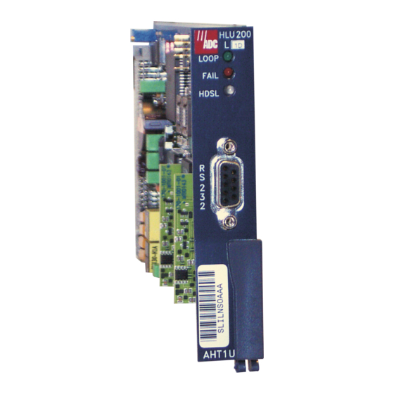
Product Overview Descriptions and Features ADC’s HiGain Line Unit Model HLU-200 List 1D (AHT1U) shown in Figure 1, is an asynchronous DS1 interface unit that plugs into the Channel Bank Assembly (CBA) of a DSC Litespan-2000 optical loop carrier system to provide an HDSL interface. The AHT1U is essentially an AT1U line unit with its T1 line interface circuit replaced by an HDSL line interface circuit. -
Page 5: Applications
150-200-114-03, Issue 03 HLU-200 List 1D features: • RS-232 maintenance port • Lightning and power cross protection on HDSL interfaces • 784 kbps full-duplex 2B1Q HDSL Transmission on two pairs • Front panel status indicating LEDs • Margin threshold alarm •... -
Page 6: Installation, Maintenance, And Provisioning
150-200-114-03, Issue 03 Figure 2 shows both doubler and non-doubler applications. Circuit A is a non-doubler application. The HRU can be placed up to 3000 feet into the network for extra range without doublers. This requires an external Network Interface Device (NID) to be placed at the Network Interface (NI). The HRU must have its SmartJack (LB) option set to DISABLE for these external NID applications. - Page 7 150-200-114-03, Issue 03 Provisioning. Note that all of the HLU-200 List 1D specific user options can only be set from its front panel RS-232 maintenance port. Only one of these options, the DS1 line code (B8ZS or AMI), is sent to the Litespan- 2000 system manager which reads the value and then provisions the Litespan Gate Array, shown in Figure 3, accordingly.
- Page 8 150-200-114-03, Issue 03 Line Circuit Settings Option. The AHT1U supports the following Line Circuit Settings Option. RETRIEVE LINE CIRCUIT SETTINGS (DLP-322) This retrieves the following information on a slot occupied by an AHT1U: Access Id. As above. b. AIS. This entry determines the type of Alarm Indicating Signal (AIS) that is sent upstream of the CBA when the AHT1U is in its alarm state.
-
Page 9: Maintenance
150-200-114-03, Issue 03 Maintenance Alarms. The AHT1U can generate two types of alarms toward the CBA. The first is caused by unplugging the HLU card after it has been ENTERED. This generates a MJ (Major), SA (service affecting) Eqpt. alarm along with the “UEQ-Unequipped”... -
Page 10: Resource Usage
150-200-114-03, Issue 03 Resource Usage Plug-In Equipment Detail. The AHT1U supports the following Plug-In Equipment Inventory Detail command; RETRIEVE PLUG-IN EQUIPMENT DETAIL (DLP-153) This command retrieves the following plug-in data: Access ID. As above b. Serial #. This field is not supported by the AHT1U CLEI Code. - Page 11 150-200-114-03, Issue 03 with minimum loss of cable pairs. In an Odd bank the last Narrowband cable pair (# 225) is not available. In an Even bank the first Narrowband cable pair (# 226) is not available. Table 3 lists the Narrowband cabling details for the Odd Litespan-2000 CBA shelves.
- Page 15 150-200-114-03, Issue 03 Table 5. ONU-96 Wideband Cabling/HDSL Loop Assignments Color Code Pin # (T - R) (Base/Ink) Tip - Ring 710 or Slot - Slot - Slot - Slot - Pair Pair Pair Pair Wh/Bl - Bl/Wh 1 - 2 26 - 1 Wh/Or - Or/Wh 3 - 4...
- Page 16 150-200-114-03, Issue 03 Table 6. ONU-96 Narrowband Cabling/HDSL Loop Assignments Color Code Pin # (T - R) (Base/Ink) Tip - Ring 710 or Slot - Slot - Slot - Slot - Circuit Circuit Circuit Circuit Wh/Bl - Bl/Wh 1 - 2 26 - 1 1 - L1 7 - L2...
-
Page 17: Functional Operation
L1 = HDSL Loop 1, L2 = HDSL Loop 2 Functional Operation The HiGain system uses ADC 2-Bit 1-Quartenary (2B1Q) HDSL transceiver systems to establish two full- duplex 784 kbps data channels between the HLU-200 List 1D and a HRU-412 HiGain Remote Unit. This provides a total capacity of 1.568 Mbps between the two units. - Page 18 150-200-114-03, Issue 03 Alternate Mark Inversion (AMI) and Bipolar 8 Bit Substitution (B8ZS) coding and decoding and hands the T1 payload off to the HDSL framer. The HLU-200 List 1D has a socket for the Interface Control Processor (ICP) which integrates the HLU-200’s Management System into the Litespan CBA Management System.
-
Page 19: Alarms
150-200-114-03, Issue 03 tip-ring reversals and for loop swaps caused by pair reversals. The HiGain system allows for tip-ring or pair reversals, but does not tolerate split pairs. By synchronizing to the Frame Sync Word (FSW) of each loop, the framer can reconstruct the original 1.544 Mbps DS1 stream from the payloads of the two HDSL loops. - Page 20 150-200-114-03, Issue 03 ALRM TLOS: A user option that causes the loss of the HRU DS1 input from the CI to initiate a logic loopback state in the HRU. ALRM H1ES: HDSL loop 1 has exceeded the 24-hour user-selected Errored Seconds CRC threshold.
-
Page 21: Options
150-200-114-03, Issue 03 Options The HLU-200 List 1D contains a non-volatile RAM (NVRAM) which stores the system option settings. All options, except the HDSL voltage polarity option, are provisioned through the RS-232 interface. They are retained if shelf power is lost or if the HLU-200 is unplugged. Table 10 lists the HLU-200 List 1D option settings. -
Page 22: Installation
Upon receipt of the equipment, visually inspect it for signs of damage. If the equipment has been damaged in transit, immediately report the extent of damage to the transportation company and to ADC. The HLU-200 List 1D mounts in a Litespan-2000 channel bank. The HLU-200 List 1D slot pinouts are shown in Figure 6. - Page 23 150-200-114-03, Issue 03 The HLU-200 is compatible with Release 7.1 and higher of the Litespan-2000 system. The HLU-200 List 1D must always be provisioned from the front panel RS-232 port as described in the Option section of this manual. Upon initial insertion into a Release 7.1.1 bank, the FAIL LED lights and remains lit. When plugged into a Release 7.1.2 or higher version, the FAIL LED lights until the handshake between the bank and HLU-200 is complete.
- Page 24 150-200-114-03, Issue 03 Row A Row B Row C Surge ground Tip 1 Loop 1 Test Loop 1 Ring 1 Tip 2 Loop 2 Test Loop 2 Ring 2 Tip 1 Loop 1 Ring 1 R222 Tip 2 Loop 2 Ring 2 Burn in SW BATT...
-
Page 25: Specifications
150-200-114-03, Issue 03 Specifications HDSL Line Code 784 kbps 2B1Q HDSL Output +13.5 dBm ±0.5 dB at 135 ohms HDSL Line Impedance 135 ohms Maximum Provisioning Loss 35 dB at 196 kHz, 135 ohms Line Clock rate Internal Stratum 4 clock HDSL Start-up Time 30 seconds (typical), 60 seconds (maximum) per span One-way DS1 Delay (HLU to HRU/HRU to HLU) -
Page 26: Loopback Operation
150-200-114-03, Issue 03 Loopback Operation The HiGain system has a family of loopback options. The most important of these is the SmartJack loopback which enables the HRU-412 to respond to the standard (2/3-in-5) SmartJack inband loopback codes and thus emulate the functions of a standard Network Interface Device (NID). This option can be enabled or disabled from the terminal SYSTEM SETTINGS MENU (Figure 12). -
Page 27: Testing
150-200-114-03, Issue 03 The green Loop LED on the HLU front panel lights whenever any of the circuit modules, HLU, HDU, or HRU, is in a loopback state. Testing Tables 11 through 16 provide step-by-step test procedures for the HLU-200 List 1D as a function of the loopback option selected. -
Page 28: Applications Using Higain Doublers
150-200-114-03, Issue 03 Table 8. HLU-200 List 1D Power Parameters for Non-Doubler Applications Power Bus HLU-200 HLU-200 HLU-200 HRU AT1U REBS CPE-I* Off CPE I On Local Power 590 mA 590 mA 590 mA 147 mA 155 mA 66 mA 66 mA 66 mA 0 mA... -
Page 29: Loopback Operation
150-200-114-03, Issue 03 Loopback Operation The HiGain system has a family of loopback options. The most important of these is the SmartJack loopback which enables the HRU-412 to respond to the standard (2/3-in-5) SmartJack inband loopback codes. This option can be enabled or disabled from the terminal SYSTEM SETTINGS Menu Screen (Figure 12). In addition to the SmartJack loopback, the HiGain system can be configured for one of five special inband loopback (SPLB) command sequences. -
Page 30: Testing
The HLU-200 List 1D and the HRU-412. The most complex HiGain system application includes the HLU-200 List 1D, HRU-412 and two inline HDU-451 Doublers. Refer to the ADC HiGain Intelligent Repeater Application Note #910, Part #325-910-100, for more SPLB details. - Page 31 150-200-114-03, Issue 03 HRU-412 HLU-200 HDSL span LOGIC TLOS HRU-412 HLU-200 HDSL span 2-in-5 Upstream SMJK* loopbacks toward HRU-412 AIS** Litespan HLU-200 HDSL span -in- backplane NREM HLU-200 Span 1 -in- 3-in-6 HRU-412 Span 2 Span 3 NDU1 NDU2 HLU-200 HRU-412 4-in-7 HDSL span...
-
Page 32: Tables
150-200-114-03, Issue 03 Tables Table 10. System Option Settings Mode Selection Description Tells HiGain that the ESF frame is operating in its ZBTSI mode. ZBTS Tells HiGain that the ESF frame is operating in its normal non-ZBTSI mode. OFF* Activates the alarm input signal to the Litespan microprocessor and flashes the red ESAL STATUS LED when 17 Errored Seconds (ES) (17 HDSL CRC errors on either HDSL loop or a total of 17 BPVs and FERR) occur within a 24-hour period. - Page 33 150-200-114-03, Issue 03 Table 10. System Option Settings (Continued) Mode Selection Description FRMG AUTO* Configures HiGain to operate in an auto-framing (AUTO) mode in which it continuously searches the input T1 bit stream for a valid SF or ESF frame pattern. This feature is required for fractional T1 applications (DS0 blocking) where it insures proper channel time slot alignment.
- Page 34 150-200-114-03, Issue 03 Table 11. HLU-200 GNLB Test Procedures Without HiGain Doublers Step Action Have the CO tester send the HRU-412 (3-in-7) inband loop-up code for five seconds. Observe that an HRU NREM loopback is in effect (see Figure 7 for non-doubler loopback configurations, Figure 8 for doubler loopback configurations).
- Page 35 150-200-114-03, Issue 03 Table 12. HLU-200 A1LB Test Procedures Step Action Send into the HLU-200 List 1D the inband ARMING and NI LPBK code 11000 for at least five seconds. Monitor the output of the HLU-200 List 1D for the return of the pattern. Return of pattern indicates that either the HRU-412 has looped-up (if the SMART-JACK LOOPBACK option is ENABLED) or that an external NI has looped up (if the SMART-JACK LOOPBACK option is DISABLED) and that the HLU-200 List 1D and HRU-412 units have been ARMED.
- Page 36 150-200-114-03, Issue 03 Table 12. HLU-200 A1LB Test Procedures (Continued) Step Action Using the following codes, a network tester can activate loopbacks NLOC or NREM or SMJK if enabled (shown in Figure 7 for non-doubler loopback configurations.) A tester at the CI can activate loopbacks CLOC or CREM.
- Page 37 150-200-114-03, Issue 03 Table 13. HLU-200 A2LB Test Procedures Step Action Send into the HLU-200 List 1D the inband ARMING and NI LPBK code 11000 for at least five seconds. Monitor the output of the HLU-200 List 1D for the return of the pattern. Return of pattern indicates that either the HRU-412 has looped-up (if the SMARTJACK LOOPBACK option is ENABLED) or that an external NI has looped up (if the SMARTJACK LOOPBACK option is DISABLED) and that the HLU-200 List 1D and HRU-412 units have been ARMED.
- Page 38 150-200-114-03, Issue 03 Table 13. HLU-200 A2LB Test Procedures (Continued) Step Action Using the following codes, a network tester can activate loopbacks NLOC or NREM or SMJK if enabled (shown in Figure 7 for non-doubler loopback configurations and Figure 16 for doubler loopback configurations.) A tester at the CI can activate loopbacks CLOC or CREM.
- Page 39 150-200-114-03, Issue 03 Table 14. HLU-200 A3LB Test Procedures Step Action The HiGain Line Unit can be looped back (NLOC in Figure 7 for non-doubler loopback configuration, NLOC in Figure 8 for doubler loopback configuration) by sending the Addressable Office Repeater (AOR) LPBK activation code 1111(F) 1111(F) 0001(1) 1110(E) for at least five seconds.
- Page 40 150-200-114-03, Issue 03 Table 15. HLU-200 A4LB Test Procedures Step Action The HiGain Line Unit can be looped back (NLOC in Figure 7 for non-doubler loopback configuration, NLOC in Figure 8 for doubler loopback configuration) by sending the Addressable Office Repeater (AOR) LPBK activation code 1111(F) 1111(F) 0001(1) 1110(E) for at least five seconds.
- Page 41 150-200-114-03, Issue 03 Table 16. HLU-200 A5LB Test Procedures (Continued) Step Action Send into the HLU-200 List 1D the inband ARMING and NI (Network Interface) LPBK code 11000 for at least five seconds, or at least four repetitions of the 16-bit ESF Data Link ARMING code 1111 1111 0100 1000 (FF48).
- Page 42 150-200-114-03, Issue 03 Table 16. HLU-200 A5LB Test Procedures (Continued) Step Action Using the following codes, a network tester can activate loopbacks NLOC or NREM or SMJK if enabled (see Figure 7 for non-doubler loopback configurations, Figure 8 for doubler loopback configurations.) A tester at the CI can activate loopbacks CLOC or CREM.
- Page 43 150-200-114-03, Issue 03 Table 17. HLU-200 Status Menu Messages Type Message Full Name Description NONE No Alarms ALARMS: RLOS Remote Loss of Signal No signal from HRU-412 remote T1 interface. LOSW1(2) Loss of Sync Word 1 HDSL loop 1 or 2 has lost sync. or 2 H1ES HDSL Loop 1 Errored...
- Page 44 150-200-114-03, Issue 03 Table 17. HLU-200 Status Menu Messages (Continued) Type Message Full Name Description NDU1 Network Doubler 1 The loopback at doubler 1 toward the CBA (Figure 8) LOOPBACKS: Loopback initiated by inband codes, or the maintenance terminal. (Doublers Only) NDU2 Network Doubler 2...
- Page 45 150-200-114-03, Issue 03 Table 18. Glossary of HiGain Terms Term Definition MARGINS Indicates the excess signal to noise ratio, at the HRU, HDU, or HLU HDSL ports, relative to a 10 BER. 1st value is current margin, 2nd value is minimum margin since (C)leared last, 3rd value is maximum value since cleared.
-
Page 46: System Maintenance Menu Screens
150-200-114-03, Issue 03 Table 19. HLU-200 GNLB Test Procedures Using HiGain Doublers Step Action Have the CO tester send the HRU-412 (3-in-7) inband loop-up code for five seconds. Observe that an HRU NREM loopback is in effect (Figure 8). The loopback state is indicated in the Span Status display screen, and by the Green Loop LED on the front panel. - Page 47 150-200-114-03, Issue 03 Figure 14 shows the PERFORMANCE DATA screen. Both the Errored and Unavailable Seconds for both HDSL loops and the remote DS1 input are listed at 15-minute intervals over a four hour time interval. Earlier and later data, in four-hour chunks on six different screens, can be accessed by pressing P (Previous) or N (Next) respectively.
- Page 48 150-200-114-03, Issue 03 Figure 10. HLU-200 List 1D Span Status Menu (Non-Doubler Applications) November 22, 1996 HLU-200 List 1D...
- Page 49 150-200-114-03, Issue 03 Figure 11. HLU-200 List 1D Set Clock Menu Figure 12. HLU-200 List 1D Terminal System Settings Main Menu HLU-200 List 1D November 22, 1996...
- Page 50 150-200-114-03, Issue 03 Figure 13. HLU-200 List 1D Terminal Loopback Menu Figure 14. HLU-200 List 1D Terminal Performance Data November 22, 1996 HLU-200 List 1D...
- Page 51 150-200-114-03, Issue 03 Figure 15. HLU-200 List 1D 7-Day Performance Data History Figure 16. HLU-200 List 1D Alarm History HLU-200 List 1D November 22, 1996...
-
Page 52: Doublers
150-200-114-03, Issue 03 Doublers Figure 17 is the Maintenance Terminal MAIN MENU Screen. Its eight sub-menus provide many useful provisioning, test and monitoring tools. Selection “H” from the MAIN MENU Screen allows the Circuit ID# to be set. It is limited to 24 alphanumeric characters. - Page 53 150-200-114-03, Issue 03 screens at both the HLU-200 List 1D and the HRU-412. The RS-232 terminal interface at the HRU-412 does not allow the counters to be cleared. Figures 33 through 35 show the ALARM HISTORY screens for Doubler applications. The alarms are defined in Paragraph 6.1.
- Page 54 150-200-114-03, Issue 03 Figure 18. HLU-200 List 1D Status Display - Span 1 (1 or 2 Doublers) Figure 19. HLU-200 List 1D Status Display - Span 2 (1 Doubler). November 22, 1996 HLU-200 List 1D...
- Page 55 150-200-114-03, Issue 03 Figure 20. HLU-200 List 1D Status Display - Span 2 (2 Doublers) Figure 21. HLU-200 List 1D Status Display - Span 3 (2 Doublers) HLU-200 List 1D November 22, 1996...
- Page 56 150-200-114-03, Issue 03 Figure 22. HLU-200 List 1D Set Clock Menu Figure 23. HLU-200 List 1D System Settings Menu November 22, 1996 HLU-200 List 1D...
- Page 57 150-200-114-03, Issue 03 Figure 24. HLU-200 List 1D Doubler Loopback Menu Figure 25. HLU-200 List 1D Performance Data - Span 1 (1 or 2 Doublers) HLU-200 List 1D November 22, 1996...
- Page 58 150-200-114-03, Issue 03 Figure 26. HLU-200 List 1D Performance Data - Span 2 (1 Doubler). Figure 27. HLU-200 List 1D Performance Data - Span 2 (2 Doublers) November 22, 1996 HLU-200 List 1D...
- Page 59 150-200-114-03, Issue 03 Figure 28. HLU-200 List 1D Performance Data - Span 3 (2 Doublers) Figure 29. HLU-200 List 1D Performance Data History - Span 1 (1 or 2 Doublers) HLU-200 List 1D November 22, 1996...
- Page 60 150-200-114-03, Issue 03 Figure 30. HLU-200 List 1D Performance Data History - Span 2 (1 Doubler) Figure 31. HLU-200 List 1D Performance Data History - Span 2 (2 Doublers) November 22, 1996 HLU-200 List 1D...
- Page 61 150-200-114-03, Issue 03 Figure 32. HLU-200 List 1D Performance Data History - Span 3 (2 Doublers) Figure 33. HLU-200 List 1D Alarm History - Span 1 (1 or 2 Doublers) HLU-200 List 1D November 22, 1996...
- Page 62 150-200-114-03, Issue 03 Figure 34. HLU-200 List 1D Alarm History - Span 2 (1 or 2 Doublers) Figure 35. HLU-200 List 1D Alarm History - Span 3 (2 Doublers) November 22, 1996 HLU-200 List 1D...
- Page 63 UPPORT ADC Customer Service Group provides expert pre-sales and post-sales support and training for all its products. Technical support is available 24 hours a day, 7 days a week by contacting the ADC Technical Assistance Center (TAC). • Quotation Proposals Sales Assistance •...
- Page 64 ADC during the 90-day warranty period is, at ADC’s option, either (a) return of the price paid or (b) repair or replace of the software. ADC also warrants that, for a period of thirty (30) days from the date of purchase, the media on which software is stored will be free from material defects under normal use.
- Page 65 ADC DSL Systems, Inc. 14402 Franklin Avenue Tustin, CA 92780-7013 Tel: 714.832.9922 Fax: 714.832.9924 Technical Assistance Tel: 800.638.0031 Tel: 714.730.3222 Fax: 714.730.2400 : 150-200-114-03, I OCUMENT SSUE ISO 9001/TL 9000 ´,4|¶3!¨ 1220923 DNV Certification, Inc. REGISTERED FIRM...