Takara Belmont YUME DX Installation Instructions Manual
Shampoo unit
Hide thumbs
Also See for YUME DX:
- Operating instructions manual (16 pages) ,
- Quick operation manual (14 pages) ,
- Operating instructions manual (20 pages)
Table of Contents
Advertisement
Quick Links
SHAMPOO UNIT
This manual provides information and instructions for YUME DX
SHAMPOO UNIT. The instructions contained in this booklet should be
thoroughly read and understood before attempting to install the equipment.
After the installation is completed, le this manual and refer back to it
for future maintenance.
YUME DX
IMPORT ANT
INSTALLATION
INSTRUCTIONS
Version 4
2018.07
1E002DC0
Advertisement
Table of Contents

Related Manuals for Takara Belmont YUME DX


Summary of Contents for Takara Belmont YUME DX
- Page 1 INSTALLATION INSTRUCTIONS IMPORT ANT This manual provides information and instructions for YUME DX SHAMPOO UNIT. The instructions contained in this booklet should be thoroughly read and understood before attempting to install the equipment. After the installation is completed, le this manual and refer back to it for future maintenance.
-
Page 2: Table Of Contents
TA B L E OF C ONT E NT S INSTA L L AT ION INST R UCT IONS 1. Overall V iew and Major Components ..1 2. Dimension & Specifications ......2 3. Plumbing L ayout........... 3 4. Contents of Unpacked Products....4 5. -
Page 3: Overall V Iew And Major Components
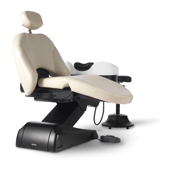
1. Overall View and Major C omponents Headres t ■Main B ody S hampoo bas in S hower head B ackres t S eat Legres t lever Legres t Original Installation date Month Year Main power s witch Service History Maintenance cover S ervice outlet Hose replacement (1 ) -
Page 4: Dimension & Specifications
2. Dimens ion & S pecifications 8° 2000 Type ------------------------------ E X -Y M2NL , E X -Y M2NR , SU-Y M2 Drive System -------------------- Motorized Hydraulic System Measurement -------------------- 760 x 2000 x 990 mm (W x L x H) A ngle of B ackrest ---------------- 67°... -
Page 5: Plumbing Layout
3. Plumbing Layout... -
Page 6: Contents Of Unpacked Products
4. Contents of Unpacked Product ●YUME DX Main Body ●Carriage Jig • Jig A • Jig B Support Bar • Jig B Bracket Screws • Jig B Neck Cushion Head Pillow Drain Cap Hair Catcher Floor Bolts Moistureproof Moistureproof Noise Reduction Tape... - Page 7 œSeat and Backrest set <SU-YM2A/SU-YM2AM> ・S eat C over (R ) ・Legres t C over ・S eat C over (L) ・S eat ・B ackres t ・Legres t fixing s crew s et ・S crew s et ・B ackres t C over ・Headres t for backres t cover ・...
-
Page 8: Installation Instruction
5. Ins tallation Ins truction 5-1. Preparations for Installations 1. Unpacking R emove nails from lower part of wooden crate. L ift up the upper portion of wooden crate. Chair will be left on the skid. Nails Nails 2. R emove the pump cover 1. -
Page 9: Marking For Unit Fixing Position
Marking 5-3. Marking for unit fixing position Use supplied full scale template to mark the fixing position on the floor. Check the piping Hot water supply pipe and power outlet position before marking. Water supply pipe 1. Put the supplied templete on the floor and hold with the tape etc. - Page 10 2. Hold the carriage jig and move the main unit to marked position on the floor. 3. Decide the installation position and remove the carriage jig A and B from main unit base. CA UT ION Hold the Jig A and B to lift the unit by 2 workers to move it.
-
Page 11: Drain Pipe Connection
5-6. Drain Pipe Connection Drain pipe(V U40) E lbow and drain pipe(V U40) are not included Drain Hos e P acking with shipment. Please prepare it beforehand. S tepped S ection Ins ert the drain hos e packing 1. Insert the elbow to the drain pipe from floor with seals. to the drain pipe(V U40) until the s tepped s ection hit to the end of drain pipe(V U40). -
Page 12: 5-8A. Remove The Fixing Bolt
5-8A. Remove the fixing bolt fixing plate 1. Remove the fixing boltb and fixing plate.(EX-YM2NA only) Fixing bolt Screw M6 Screw M6 2. Remove the fixing bolt for carriage. Fixing Bolt for carriage -10-... -
Page 13: 5-8B . Unit Power Supply L Ine
5-8B . Unit Power Supply L ine Power Cable Fix the plug on the end of the unit power cable. Power Supply Outlet Plug the unit power cable into the suitable power supply outlet. 5-9. Installation of B ase Cover 1. -
Page 14: Mount The Seat Cushion
5-10. Mount the seat cushion Apron Seat Leg-rest frame <Model. SU-YM2A / SU-YM2AM> 1. Attach the seat to the main body (M6x15). 2. Fix the seat to the leg-rest frame. (Shoulder screw (M8), plastic washer and metal washer) Leg-rest 3. Mount the leg-rest cover on the frame. cover Plastic washer (M4x10) -
Page 15: Attach The Backrest
seat apron Note: In attaching the seat cover, the apron to be put on the seat cover as the figure shows. seat cover backrest frame 5-12. Attach the backrest braces 1. Raise the backrest frame by pressing P2 button. 2. Fit the backrest into the braces of the frame, then fix it with the screws (M6x20). -
Page 16: Fix The Backrest Cover
<Without headrest model no. SU-YM2A and SU-YM2B only> 1. Insert the short-circuit connector enclosed with the backrest into the one from the main body. Connector from the backrest Connector from the backrest Connector from mainbody Connector from the main body 2. -
Page 17: Attach The Neck Cushion
5-15. Attach the Neck Cushion Neck Cushion Hook 1. Attach the neck cushion on metal fittings as shown in the figure. Fixed Pin Metal Fitting 2. Both side hooks of the neck cushion are fixed to pins. Hook Hook 5-16. Attach the Head Pillow 1. - Page 20 NOTE TAK AR A B E LMONT C OR P OR AT ION 1-1, 2-C home, Higas hi-s hins aibas hi,C huo-ku,Os aka,J apan T E L : (06) 6213-5945 FAX : (06) 6212-3680 P rinted in J apan...