Panasonic MC-CG717 Service Manual
Hide thumbs
Also See for MC-CG717:
- Operating instructions manual (10 pages) ,
- Operating instructions manual (10 pages) ,
- Operating instructions manual (20 pages)
Table of Contents
Advertisement
Quick Links
TABLE OF CONTENTS
1 Specifications ----------------------------------------------------- 2
2 Schematic Diagram ---------------------------------------------- 2
3 Wiring Connection ----------------------------------------------- 3
3.1. CDS ----------------------------------------------------------- 3
3.2. ECM (Alternative)------------------------------------------ 4
4 Trouble Shooting Chart ---------------------------------------- 5
5 Disassembly and Assembly Instruction ------------------ 7
5.1. Disassembly of Upper and Lower Body ------------- 7
5.2. Disassembly of Motor Case Set ----------------------- 9
5.3. Disassembly of Cord Reel Unit ------------------------ 9
5.4. Disassembly of Rail Base Unit ------------------------10
5.5. Disassembly of Fan Motor Unit -----------------------10
5.6. Disassembly of P.C.B. Ass'y---------------------------12
6 Exploded View and Replacement Parts List -----------13
6.1. Exploded View --------------------------------------------13
6.2. Attachment Exploded View ----------------------------14
6.3. Packing Instruction ---------------------------------------15
6.4. Replacement Parts List ---------------------------------16
Model No.
PAGE
© 2011 Panasonic Manufacturing Malaysia Berhad
(6100-K). Unauthorized copying and distribution is a
violation of law.
Vacuum Cleaner
MC-CG717
PMMA110825CE
PAGE
Advertisement
Table of Contents

Related Manuals for Panasonic MC-CG717


Summary of Contents for Panasonic MC-CG717
-
Page 1: Table Of Contents
6 Exploded View and Replacement Parts List -----------13 6.1. Exploded View --------------------------------------------13 6.2. Attachment Exploded View ----------------------------14 6.3. Packing Instruction ---------------------------------------15 6.4. Replacement Parts List ---------------------------------16 © 2011 Panasonic Manufacturing Malaysia Berhad (6100-K). Unauthorized copying and distribution is a violation of law. -
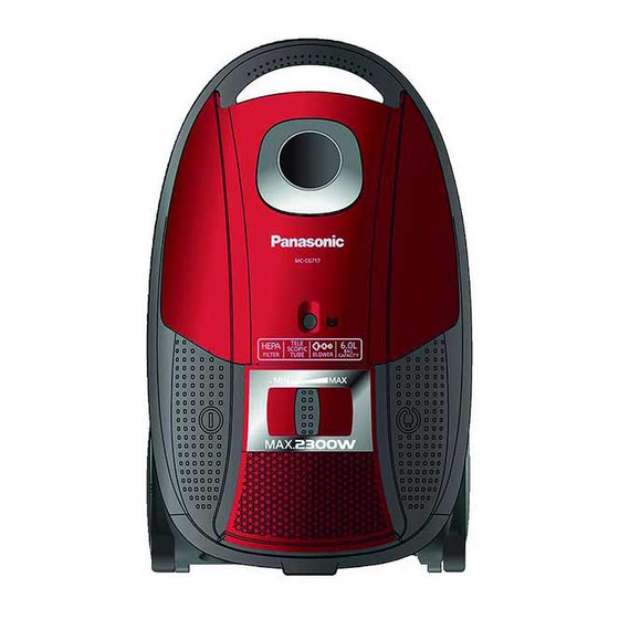
Page 2: Specifications
1 Specifications Model MC-CG717 Power Source 220V~240V~50/60Hz Input Power (Max) 2300W Input Power (IEC) 1600-2000W Power Control SLIDE Dust Capacity 6.0L Automatic Cord Rewind Vac Gauge Exhaust Filter HEPA Extension Wands MAGIC TELESCOPIC WAND Blower Operation Floor Nozzle 2-STEP Dust Bag... -
Page 3: Wiring Connection
3 Wiring Connection 3.1. -
Page 4: Ecm (Alternative)
3.2. ECM (Alternative) -
Page 5: Trouble Shooting Chart
4 Trouble Shooting Chart... -
Page 7: Disassembly And Assembly Instruction
5 Disassembly and Assembly Instruction 5.1. Disassembly of Upper and Step 4 Pull out Exhaust Cover. Lower Body Step 1 Open Dust Cover & remove Dust Bag. Step 2 Release Dust Cover from Hanger. Step 5 Remove 3 screws from back side of body. Step 3 Remove 5 screws from the Front Side and 2 screws from Bottom Side of the body.. - Page 8 Step 7 Remove Body Lining Upper using philip screwdriver. Step 10 Lift up Upper Body. Step 11 Remove Upper Body from Lower Body. Step 8 Push one by one follow the arrow to take out the pedal. Step 9 Pull the On/Off switch to change position.
-
Page 9: Disassembly Of Motor Case Set
5.2. Disassembly of Motor Case Set 5.3. Disassembly of Cord Reel Unit Step 1 Release Rear Cover from Screw Holders. Step 1 Release the pretension of the Cord Reel Unit slowly by Step 2 Remove Rear Cover. holding on the Power Plug and pressing on the Brake Lever. Step 3 Pull up Motor Case Set from Lower Body. -
Page 10: Disassembly Of Rail Base Unit
5.4. Disassembly of Rail Base Unit Disassembly of Fan 5.5. Step 1 Remove 1 screw. Motor Unit Step 1 Remove Swivel Cap. Step 2 Remove 1 screw from top and 2 screws bottom Motor Case Set. Step 2 Release Catch and pull upward. Step 3 Remove Tabs. - Page 11 Step 4 Lift up Motor Case Unit Step 6 Remove Noise Supprassor Unit and Motor Support Rubbers. Step 5 Disconnect Wire Terminal and remove Motor Set.
-
Page 12: Disassembly Of P.c.b. Ass
Disassembly of P.C.B. 5.6. Ass’y Step 1 Disassemble Volume by widening the Tab using Screw- driver. Step 2 Remove Volume Upward. Step 3 Release Tabs and remove P.C.B. Cover. To reassemble the unit, reverse the disassembly proce- dure above. -
Page 13: Exploded View And Replacement Parts List
6 Exploded View and Replacement Parts List 6.1. Exploded View Plug E2 Plug C3... -
Page 14: Attachment Exploded View
6.2. Attachment Exploded View... -
Page 15: Packing Instruction
6.3. Packing Instruction EXTENSION WAND UNIT HOSE UNIT PARTITION BOARD A CONNECTION PIPE CURVED WAND FLOOR NOOZLE ASS'Y DUSTING BRUSH A CREVICE NOZZLE BODY INSTRUCTION BOOK... -
Page 16: Replacement Parts List
6.4. Replacement Parts List Safety Ref. No. Part No. Part Name & Description Remarks XTN4+20BFJ PAN TAP SCREW XTN4+10FFJ SCREW XTN4+14BFJ TAPPING SCREW XTN4+12BFJ PAN TAP SCREW XTN4+12BFJ PAN TAP SCREW YMV02ABW000 UPPER BODY YMV32KBW000 FILTER SUPPORTER YMV42KBW000 FILTER CASE YMV95KBW000 FILTER ASS'Y YMV96LBW000...