Table of Contents
Advertisement
Advertisement
Table of Contents

Related Manuals for Kohler CH11-16


Summary of Contents for Kohler CH11-16
- Page 1 ERVICE ANUAL COMMAND CH11-16 ORIZONTAL RANKSHAFT...
-
Page 2: Table Of Contents
Section 1. Safety and General Information ... Section 2. Tools & Aids ... Section 3. Troubleshooting ... Section 4. Air Cleaner and Air Intake System ... Section 5. Fuel System and Governor ... Section 6. Lubrication System ... Section 7. Retractable Starter ... Section 8. -
Page 3: Section 1. Safety And General Information
Safety and General Information Safety Precautions To ensure safe operation please read the following statements and understand their meaning. Also refer to your equipment manufacturer's manual for other important safety information. This manual contains safety precautions which are explained below. Please read carefully. WARNING Warning is used to indicate the presence of a hazard that can cause severe personal injury, death, or substantial property damage if the warning is ignored. - Page 4 Section 1 Safety and General Information WARNING Explosive Fuel can cause fires and severe burns. Do not fill the fuel tank while the engine is hot or running. Explosive Fuel! Gasoline is extremely flammable and its vapors can explode if ignited. Store gasoline only in approved containers, in well ventilated, unoccupied buildings, away from sparks or flames.
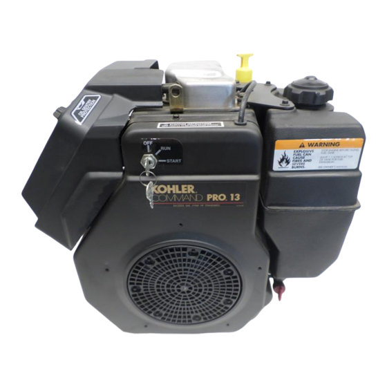
- Page 5 2005 2006 2007 Section 1 Identification Decal MODEL NO. CH12.5ST 1903 SPEC. NO. SERIAL NO. 2005810334 REFER TO OWNER'S MANUAL FOR SAFETY, MAINTENANCE SPECS AND ADJUSTMENTS. FOR SALES AND SERVICE IN US/CANADA CALL: 1-800-544-2444. www.kohlerengines.com KOHLER CO. KOHLER, WI USA...
- Page 6 Gasoline/Alcohol blends Gasohol (up to 10% ethyl alcohol, 90% unleaded gasoline by volume) is approved as a fuel for Kohler engines. Other gasoline/alcohol blends are not approved. Gasoline/Ether blends Methyl Tertiary Butyl Ether (MTBE) and unleaded gasoline blends (up to maximum of 15% MTBE by volume) are approved as a fuel for Kohler engines.
- Page 7 • Have solenoid shift starter disassembled and cleaned Perform these maintenance procedures more frequently under extremely dusty, dirty conditions. Only required for Denso starters. Not necessary on Delco starters. Have a Kohler Engine Service Dealer perform this service. Storage If the engine will be out of service for two months or more, use the following storage procedure: 1.
- Page 8 Section 1 Safety and General Information Figure 1-4. Typical Engine Dimensions. Dimensions in millimeters. Inch equivalents shown in ( ).
- Page 9 General Specifications Power (@ 3600 RPM, exceeds SAE J1940 HP standards) CH11 ... 8.20 kW (11 HP) CH12.5 ... 9.33 kW (12.5 HP) CH13 ... 9.75 kW (13 HP) CH14 ... 10.50 kW (14 HP) CH15 ... 11.20 kW (15 HP) CH16 ...
- Page 10 Section 1 Safety and General Information Camshaft End Play (Free) ... 0.0875/0.3925 mm (0.0034/0.0154 in.) End Play (with Shims) ... 0.0762/0.1270 mm (0.0030/0.0050 in.) Running Clearance ... 0.025/0.1050 mm (0.00098/0.0041 in.) Bore I.D. New ... 20.000/20.025 mm (0.7874/0.7884 in.) Max. Wear Limit ... 20.038 mm (0.7889 in.) Camshaft Bearing Surface O.D.
- Page 11 Crankshaft End Play (Free) ... 0.0575/0.4925 mm (0.0022/0.0193 in.) End Play (Thrust Bearing with Shims) ... 0.0500/0.5300 mm (0.0019/0.0208 in.) Crankshaft Bearing I.D. (In Crankcase) Sleeve Bearing (Installed) - New ... 44.965/45.003 mm (1.7703/1.7718 in.) Sleeve Bearing - Max. Wear Limit ... 45.016 mm (1.7723 in.) Parent Material (No Sleeve Bearing) - New ...
- Page 12 Section 1 Safety and General Information Cylinder Bore I.D. cont'd. Max. Out-of-Round CH11-14 ... 0.12 mm (0.0047 in.) CH15, CH16 ... 0.12 mm (0.0047 in.) Max. Taper CH11-14 ... 0.05 mm (0.0020 in.) CH15, CH16 ... 0.05 mm (0.0020 in.) Cylinder Head Cylinder Head Fastener Torque (torque in 2 increments) ...
- Page 13 Ignition Spark Plug Type (Champion ® or equivalent) ... RC12YC or Platinum 3071 Spark Plug Gap CH11-15 ... 1.02 mm (0.040 in.) CH16 ... 0.76 mm (0.030 in.) Spark Plug Torque ... 38.0-43.4 N·m (28-32 ft. lb.) Ignition Module Air Gap ... 0.203/0.305 mm (0.008/0.012 in.) Ignition Module Fastener Torque ...
- Page 14 Section 1 Safety and General Information Piston Thrust Face-to-Cylinder Bore Running Clearance - New CH11-14 ... 0.041/0.044 mm (0.0016/0.0017 in.) CH15, CH16 ... 0.031/0.043 mm (0.0012/0.0016 in.) Retractable Starter Center Screw Torque ... 7.4-8.5 N·m (65-75 in. lb.) Throttle/Choke Controls Governor Control Lever Fastener Torque ...
- Page 15 General Torque Values Metric Fastener Torque Recommendations for Standard Applications Tightening Torque: N·m (in. lb.) + or - 10% Size 1.2 (11) 1.7 (15) 2.5 (22) 3.2 (28) 4.3 (38) 5.7 (50) 10.5 (93) 13.6 (120) Tightening Torque: N·m (ft. lb.) + or - 10% 21.7 (16) 27.1 (20) 36.6 (27)
-
Page 16: Section 2. Tools & Aids
By using tools designed for the job, you can properly service engines easier, faster, and safer! In addition, you’ll increase your service capabilities and customer satisfaction by decreasing engine downtime. Here is the list of tools and their source. Separate Tool Suppliers: Kohler Tools Contact your source of supply. &... - Page 17 Section 2 Tools & Aids ) . t t f i l l a c i l f i l i t i & l i o i f i i f i i f i . s r a l i l a i l l a l l a...
- Page 18 - l e i l i ® e t i l i o s i s e t i ® ® e t i e t i ® e t i ® ® e t i ) t f . r e , s t s i l s i r...
- Page 19 4. Use a flat washer with the correct I.D. to slip on the capscrew and approximately 1” O.D. (Kohler Part No. 12 468 05-S). Assemble the capscrew and washer to the joint surface of the rod, as shown in Figure 2-2.
-
Page 20: Section 3. Troubleshooting
Troubleshooting Guide When troubles occur, be sure to check the simple causes which, at first, may seem too obvious to be considered. For example, a starting problem could be caused by an empty fuel tank. Some common causes of engine trouble are listed below. - Page 21 Section 3 Troubleshooting Engine Knocks 1. Excessive engine load. 2. Low crankcase oil level. 3. Old or improper fuel. 4. Internal wear or damage. Engine Loses Power 1. Low crankcase oil level. 2. High crankcase oil level. 3. Dirty air cleaner element. 4.
- Page 22 Basic Engine Tests Crankcase Vacuum Test A partial vacuum should be present in the crankcase when the engine is operating at normal temperatures. Pressure in the crankcase (normally caused by a clogged or improperly-assembled breather) can cause oil to be forced out at oil seals, gaskets, or other available spots.
- Page 23 Section 3 Troubleshooting Compression Test These engines are equipped with an automatic compression release (ACR) mechanism. Because of the ACR mechanism, it is difficult to obtain an accurate compression reading. As an alternate, use the leakdown test described below. Cylinder Leakdown Test A cylinder leakdown test can be a valuable alternative to a compression test.
-
Page 24: Section 4. Air Cleaner And Air Intake System
Air Cleaner and Air Intake System Air Cleaner General These engines are equipped with a replaceable, high- density paper air cleaner element. Most are also equipped with an oiled-foam precleaner which surrounds the paper element. See Figures 4-1 and 4-2. Air Cleaner Cover Knob Air Cleaner... -
Page 25: Section 4 Air Cleaner And Air Intake System
4. Do not wash the paper element or use pressurized air, as this will damage the element. Replace a dirty, bent, or damaged element with a genuine Kohler element. Handle new elements carefully; do not use if the sealing surfaces are bent or damaged. -
Page 26: Section 5. Fuel System And Governor
(see Figure 5-1), must use Low Permeation SAE 30 R7 rated fuel line; certified to meet CARB requirements. Standard fuel line may not be used. Order replacement hose by part number through a Kohler Engine Service Dealer. IMPORTANT ENGINE INFORMATION THIS ENGINE MEETS U.S. - Page 27 Section 5 Fuel System and Governor Fuel System Tests When the engine starts hard, or turns over but will not start, it is possible that the problem is in the fuel system. To find out if the fuel system is causing the problem, perform the following tests. Troubleshooting - Fuel System Related Causes Test 1.
- Page 28 Replacing the Fuel Pump Nonmetallic fuel pumps are not serviceable and must be replaced when faulty. Replacement pumps are available in kits that include the pump, fittings, and mounting gasket. 1. Disconnect the fuel lines from the inlet and outlet fittings.
- Page 29 Section 5 Fuel System and Governor Carburetors These engines, based upon when produced, are equipped with either an adjustable main jet carburetor, or an emission compliant fixed jet carburetor manufactured be Walbro or Nikki. See Figure 5-4. Walbro carburetors have a low idle speed screw and a low idle fuel adjusting needle.
- Page 30 Condition 1. Engine starts hard, or 1. Low idle fuel mixture or speed are improperly adjusted. Adjust the low idle runs roughly or stalls at speed screw, then adjust the low idle fuel needle (adjustable carburetors), or idle speed. clean the carburetor as required (fixed jet carburetors). 2.
- Page 31 Section 5 Fuel System and Governor Adjustment NOTE: Carburetor adjustments should be made only after the engine has warmed up. Emission Compliant Non-Adjustable Carburetors In compliance with current government emission standards, carburetors on later production engines are calibrated to deliver the correct fuel-to-air mixture to the engine under all operating conditions, without external adjustments, except for low idle speed (RPM).
- Page 32 Adjust Carburetor (Adjustable Main Jet) 1. With the engine stopped turn the low and high idle fuel adjusting needles in (clockwise) until they bottom lightly. NOTE: The tip of the idle fuel and high idle fuel adjusting needles are tapered to critical dimensions.
- Page 33 Section 5 Fuel System and Governor Disassembly 1. Remove the power screw, needle and spring, main jet, power screw gasket and fuel bowl. 2. Remove the bowl gasket, float shaft, float, and fuel inlet needle. Throttle Plate Screw(s) Throttle Plate Low Idle Speed Adjusting Screw and Spring Low Idle Fuel Adjusting...
- Page 34 Welch Plug Removal In order to clean the “off-idle” ports and bowl vent thoroughly, remove the welch plug covering these areas. Use Tool No. KLR1018 and the following procedure to remove the welch plug. See Figure 5-9. 1. Pierce the welch plug with the tip of the tool. NOTE: To prevent damage to the carburetor, do not allow the tool to strike the carburetor body.
- Page 35 Section 5 Fuel System and Governor 4. Remove the throttle lever/shaft assembly with foam dust seal. Cleaning WARNING: Flammable Solvents! Carburetor cleaners and solvents are extremely flammable. Keep sparks, flames, and other sources of ignition away from the area. Follow the cleaner manufacturer’s warnings and instructions on its proper and safe use.
- Page 36 4. Apply finger pressure to the throttle lever/shaft to keep it firmly seated against the pivot in the carburetor body. Rotate the throttle shaft until the throttle plate closes the bore around its entire perimeter; then tighten the screws. See Figure 5-12.
- Page 37 Section 5 Fuel System and Governor 5. Install the bowl gasket, fuel bowl, bowl retainer gasket, and bowl screw/shut-off solenoid/power screw, as equipped. Torque to: 5.1-6.2 N·m (45-55 in. lb.). High Altitude Operation When operating the engine at altitudes of 1830 m (6000 ft.) and above, the main fuel mixture tends to get overrich.
- Page 38 4. Remove the upper brass bushing using one of the following procedures: a. Use a slide hammer type bearing puller. b. Use a #3 (for 5-32 dia. hole) screw extractor. Secure extractor in a vise. Turn carburetor on to the extractor. While pulling on the carburetor, lightly tap the carburetor casting with a hammer or use a size 12-28 tap if a #3 screw extractor is not available.
- Page 39 Section 5 Fuel System and Governor The regulating pin contacts the tab on the cross shaft, causing the shaft to rotate when the engine speed changes. One end of the cross shaft protrudes through the side of the crankcase. Through external linkage attached to the cross shaft, the rotating action is transmitted to the throttle lever of the carburetor.
-
Page 40: Section 6. Lubrication System
Lubrication System Oil Recommendations Using the proper type and weight of oil in the crankcase is extremely important. So is checking oil daily and changing oil regularly. Failure to use the correct oil, or using dirty oil, causes premature engine wear and failure. - Page 41 Figure 6-4. Oil Filter and Oil Sentry™. Change Oil Filter Replace the oil filter at least every other oil change (every 200 hours of operation). Always use a genuine Kohler oil filter. Replace the oil filter as follows. Oil Filter...
-
Page 42: Lubrication System
1. Drain the oil from the engine crankcase. 2. Allow the oil filter to drain. 3. Before removing the oil filter, clean the area around the oil filter to keep dirt and debris out of the engine. Remove the old oil filter. Wipe off the surface where the oil filter mounts. - Page 43 Section 6 Lubrication System Figure 6-9. New Relief Valve. Oil Sentry™ Oil Pressure Monitor Some engines are equipped with an optional Oil Sentry™ oil pressure monitor. See Figure 6-5. Oil Sentry™ will either stop the engine or activate a “low oil”...
-
Page 44: Section 7. Retractable Starter
Retractable Starter WARNING: Spring Under Tension! Retractable starters contain a powerful, recoil spring that is under tension. Always wear safety goggles when servicing retractable starters and carefully follow instructions in this section for relieving spring tension. Starter Housing Flange Screws Spring and Keeper Pulley... - Page 45 Section 7 Retractable Starter 3. Remove the rope retainer from inside the starter handle. Untie the single knot and remove the rope retainer and handle. 4. Hold the pulley firmly and untie the slip knot. Allow the pulley to rotate slowly as the spring tension is released.
- Page 46 2. Replace all worn or damaged components. Use only genuine Kohler replacement parts as specified in the Parts Manual. All components shown in Figure 7-1, are available as service parts. Do not use nonstandard parts.
- Page 47 Section 7 Retractable Starter Housing Figure 7-9. Installing Pulley and Spring into Housing. 4. Install the pawl springs and pawls into the starter pulley. See Figure 7-10. Pawl Figure 7-10. Installing Pawls and Pawl Springs. 5. Place the brake washer in the recess in starter pulley;...
-
Page 48: Section 8. Electrical System And Components
The standard spark plug is a Champion RC12YC (Kohler Part No. 12 132 02-S). A high-performance spark plug, Champion Platinum 3071 (used on Pro Series engines, Kohler Part No. 25 132 12-S) is also available. Equivalent alternate brand plugs can also be used. Gap: CH11-15 1.02 mm (0.040 in.) - Page 49 Section 8 Electrical System and Components Inspection Inspect the spark plug when it is removed from the cylinder head. The deposits on the tip are an indication of the general condition of the piston rings, valves, and carburetor. Normal and fouled plugs are shown in the following photos.
- Page 50 Battery General A 12 volt battery with a rating of approximately 32 amp hours/250 cold cranking amps is normally used. Refer to the operating instructions of the equipment this engine powers for specific information. Recharge the battery if the charge is not sufficient to crank the engine.
- Page 51 Section 8 Electrical System and Components Electronic Magneto Ignition System, CH11-15 Engines Air Gap 0.2-0.3 mm (0.008-0.012 in.) Flywheel Kill Switch or Off Position of Key Switch Figure 8-3. Electronic Magneto Ignition System, CH11-15 Engines. These engines are equipped with a dependable electronic magneto ignition system.
- Page 52 Magneto Ignition System Troubleshooting Guide The following guide will help locate and correct ignition system-related starting problems. Refer to Section 2, “Tools & Aids” for ignition system tester. NOTE: Use a low-voltage (2 volts or less) ohmmeter when ohmmeter is required. Always zero ohmmeter on each scale before testing to ensure accurate readings.
- Page 53 Section 8 Electrical System and Components Electronic Ignition System with Spark Advance (Smart Spark Kill Switch or Off Position of Key Switch Figure 8-5. Capacitive Discharge Ignition System with Spark Advance. CH16 engines are equipped with an electronic capacitive discharge ignition system with electronic spark advance.
- Page 54 The trigger pulse exiting the SAM activates the reset circuit, discharging the capacitor and resetting the circuits for the next cycle. From rown Conditioning Input Circuit Coil Spark Advance Module (SAM) Brown Figure 8-7. Troubleshooting CD Ignition Systems The CD ignition system is designed to be trouble-free for the life of the engine.
- Page 55 Section 8 Electrical System and Components ™ Testing of Smart Spark Ignition Systems The following procedure is provided for troubleshooting ignition problems on CH16 engines. It will allow you to pinpoint the failed components. Special Tools Required: • Ignition System Tester* (see Section 2) •...
- Page 56 Electrical Systems Wiring Diagrams and Battery Charging Systems This engine is equipped with a regulated battery charging system. Refer to the following wiring diagram and troubleshooting guide to test and service this system. NOTE: Observe the following guidelines to prevent damage to the electrical system and components.
- Page 57 Section 8 Electrical System and Components Troubleshooting Guide - 15/20 amp Battery Charging System NOTE: Zero ohmmeters and voltmeters on each scale to ensure accurate readings. Voltage tests should be made with the engine running at 3600 RPM - no load. The battery must be fully charged. Problem 1.
- Page 58 Electric Starters Some engines in this series use inertia drive starting motors while others use solenoid shift type. Inertia drive types are covered first and the solenoid shift type is covered starting on page 8.16. NOTE: Do not crank the engine continuously for more than 10 seconds at a time.
- Page 59 4. Clean the splines on the drive shaft thoroughly with solvent. Dry the splines thoroughly. 5. Apply a small amount of Kohler electric starter drive lubricant, (see Section 2) to the splines. The use of other lubricants may cause the drive pinion to stick or bind.
- Page 60 If the splines are dirty, clean them with solvent. 7. The splines should have a light film of lubricant. Relubricate as necessary with Kohler bendix starter lubricant (see Section 2). Reinstall or replace the drive components, assembling them in the same sequence as they were removed.
- Page 61 Section 8 Electrical System and Components Retaining Ring Installation 1. Position the retaining ring in the groove in one of the inner halves. Assemble the other half over the top and slide on the outer collar. 2. Be certain the drive components are installed in correct sequence onto the armature shaft.
- Page 62 Figure 8-18. Style "B" Commutator End Cap with Brushes. 6. Install the thru bolts and tighten securely. 7. Lubricate the drive shaft with Kohler bendix starter drive lubricant (see Section 2). Install the drive components following the instructions for servicing the drive.
- Page 63 Section 8 Electrical System and Components Solenoid Shift Electric Starters The following subsection covers the solenoid shift electric starters. Some of the information in the preceding subsection relates also to this style of starter, so it is not repeated here. A Nippondenso or Delco-Remy solenoid shift starter may be used.
- Page 64 Reinstall the springs. Snap the insulator into the brush holder to keep the springs from popping out. Starter Service Clean drive lever and armature shaft. Apply Kohler electric starter drive lubricant (See Section 2) to lever and shaft. Starter Reassembly 1.
- Page 65 Section 8 Electrical System and Components Figure 8-22. Mounting Brush Holder to Frame. 8. Position the insulator over the brushes and springs. Hold it firmly in place so the springs do not come out. See Figure 8-23. Figure 8-23. Holding Insulator in Place. 9.
- Page 66 Figure 8-27. Installing Solenoid. 14. Connect the braided (brush) lead to lower main solenoid terminal and secure with the hex flange nut. See Figure 8-28. Figure 8-28. Connecting Brush Lead. Delco-Remy Starters Figure 8-29. Delco-Remy Starter. Starter Disassembly 1. Remove the hex nut and disconnect the positive (+) brush lead/bracket from the solenoid terminal.
- Page 67 Section 8 Electrical System and Components Figure 8-32. Removing Plunger. 4. Remove the two thru (larger) bolts. See Figure 8-33. Figure 8-33. Removing Thru Bolts. 5. Remove the commutator end plate assembly, containing the brush holder, brushes, springs, and locking caps. Remove the thrust washer from inside the commutator end.
- Page 68 Figure 8-37. Armature and Lever Removed. 10. Push the stop collar down to expose the retaining ring. See Figure 8-38. Figure 8-38. Retaining Ring Details. 11. Remove the retainer from the armature shaft. Save the stop collar. NOTE: Do not reuse the old retainer. Figure 8-39.
- Page 69 Brush Replacement The brushes and springs are serviced as a set (4). Use Brush and Spring Kit, Kohler Part No. 52 221 01-S, if replacement is necessary. 1. Perform steps 1-5 in Starter Disassembly. 8.22 2.
- Page 70 Starter Reassembly 1. Apply new drive lubricant (See Section 2) to the armature shaft splines. Install the drive pinion onto the armature shaft. 2. Install and assemble the stop collar/retainer assembly. a. Install the stop collar down onto the armature shaft with the counter bore (recess) b.
- Page 71 Section 8 Electrical System and Components 8. Install the frame with the small notch forward, onto the armature and drive end cap. Align the notch with the corresponding section in the rubber grommet. Install the drain tube in rear cutout, if it was removed previously. See Figure 8-49.
- Page 72 Figure 8-53. Brush Installation Tool with Extension. d. Hold the starter assembly vertically on the end housing, and carefully place the tool (with extension) and assembled original brush holder assembly onto the end of the armature shaft. Slide the brush holder assembly down into place around the commutator, install the positive (+) brush lead grommet in the cutout of the frame.
- Page 73 Section 8 Electrical System and Components Solenoid Test Procedure Solenoid Shift Style Starters Disconnect all leads from the solenoid including the positive brush lead attached to the lower stud terminal. Remove the mounting hardware and separate the solenoid from the starter for testing. Test 1 Solenoid Pull-In Coil/Plunger Actuation Use a 12 volt power supply and two test leads.
- Page 74 Test 4 Solenoid Hold-In Coil/Contact Continuity Test Use an ohmmeter set to the audible or Rx2K scale, and connect the two ohmmeter leads to the two large post terminals. Perform the preceding test (3) and check for continuity. See Figure 8-61. The meter should indicate continuity, if no continuity is indicated the solenoid should be replaced.
-
Page 75: Section 9. Disassembly
WARNING: Accidental Starts! Disabling engine. Accidental starting can cause severe injury or death. Before working on the engine or equipment, disable the engine as follows: 1) Disconnect the spark plug lead(s). 2) Disconnect negative (-) battery cable from battery. General The following sequence is suggested for complete engine disassembly. - Page 76 Section 9 Disassembly Remove Muffler 1. Remove the four hex flange screws securing the muffler to the upper and lower mounting brackets. See Figures 9-2 and 9-3. 2. Remove the muffler from the mounting brackets and exhaust inlet pipe. 3. Remove the two hex flange nuts from the exhaust port studs and take off the exhaust inlet pipe and gasket.
- Page 77 3. Remove the hex flange nuts from the mounting studs, and take off the air cleaner mounting bracket, spitback cup or collector plate, and gasket as equipped. See Figure 9-6. Air Cleaner Base Intake Studs Figure 9-6. Removing Spitback Cup and Air Cleaner Base.
- Page 78 Section 9 Disassembly Remove Carburetor and Governor Lever WARNING: Explosive Fuel! Gasoline may be present in the carburetor and fuel system. Gasoline is extremely flammable, and its vapors can explode if ignited. Keep sparks, open flames, and other sources of ignition away from the engine.
- Page 79 Remove Fuel Pump WARNING: Explosive Fuel! Gasoline may be present in the carburetor and fuel system. Gasoline is extremely flammable, and its vapors can explode if ignited. Keep sparks, open flames, and other sources of ignition away from the engine. 1.
- Page 80 Section 9 Disassembly d. If removal of the mounting studs is required, use the two hex flange nuts from the mounting studs, tightened flange to flange, to remove. See Figure 9-18. Hex Flange Nuts Figure 9-18. Removing Mounting Studs. If the starter is mounted with two hex flange screws, remove the screws and pull the starter out from behind the pinion cover.
- Page 81 Remove Valve Cover 1. Remove the five hex flange valve cover screws. Note the assembly orientation of any attached brackets (lift, fuel tank, muffler) and loose spacers if used. See Figure 9-22. NOTE: The valve cover is sealed to the cylinder head using RTV silicone sealant.
- Page 82 Section 9 Disassembly Remove Carburetor Adapter and Heat Deflector 1. Remove the two socket head cap screw securing carburetor adapter, gaskets and heat deflector to the cylinder head. See Figure 9-27. 2. Remove the carburetor adapter, heat shield, and gaskets from the engine. See Figure 9-27. Figure 9-27.
- Page 83 Disassemble Cylinder Head Two basic types of heads are used. One type utilizes a rocker bridge arrangement as shown in Figure 9-33. The second type uses individually mounted rocker arm assemblies, with or without a guide plate, rather than a bridge. This type is shown in Figure 9-32. Components are unique to each style of head.
- Page 84 Section 9 Disassembly Figure 9-36. Removing Valves. Remove Drive Cup, Grass Screen, Flywheel, and Fan NOTE: Always a the flywheel strap wrench or holding tool to hold the flywheel when loosening or tightening the flywheel and fan retaining fasteners. Do not use any type of bar or wedge between the fins of cooling fan as the fins could become cracked or damaged.
- Page 85 Figure 9-40. Removing Stator. Remove Closure Plate 1. Remove the twelve hex flange screws securing the closure plate to the crankcase. See Figure 9-41. Figure 9-41. Removing Closure Plate. 2. Locate the splitting notches in the seam of the closure plate and crankcase. See Figure 9-42. Pry the closure plate from the crankcase using a large flat-blade screwdriver.
- Page 86 Section 9 Disassembly Figure 9-45. Later Style Oil Pressure Relief Valve. *NOTE: Later style one-piece relief valves (Figure 9-45) are staked in place and do not require removal unless replacement is intended. 4. Remove the three hex flange screws, oil pump cover, O-Ring, and oil pump rotors.
- Page 87 Remove Balance Shaft 1. Remove the balance shaft from the crankcase. See Figure 9-49. Figure 9-49. Removing Balance Shaft. Remove Connecting Rod and Piston 1. Remove the two hex flange screws and connecting rod cap. See Figure 9-50. NOTE: If a carbon ridge is present at the top of the bore, use a ridge reamer tool to remove it before attempting to remove the piston.
- Page 88 Section 9 Disassembly Remove Crankshaft 1. Remove the woodruff key from the flywheel end of crankshaft. 2. Remove the crankshaft from the crankcase. See Figure 9-53. Crankshaft Figure 9-53. Removing Crankshaft. Remove Flywheel End Oil Seal 1. Remove the oil seal from crankcase. Remove Governor Cross Shaft and Governor Gear 1.
-
Page 89: Section 10. Inspection And Reconditioning
Inspection and Reconditioning This section covers the operation, inspection, and repair/reconditioning of major internal engine components. The following components are not covered in this section. They are covered in sections of their own: Air Cleaner, Section 4 Carburetor & External Governor, Section 5 Ignition, Charging &... - Page 90 Section 10 Internal Components Inspect the crankshaft keyways. If worn or chipped, replacement of the crankshaft will be necessary. Inspect the crankpin for score marks or metallic pickup. Slight score marks can be cleaned with crocus cloth soaked in oil. If wear limits, as stated in “Specifications and Tolerances”...
- Page 91 Replace the flywheel, the crankshaft, and the key if flywheel key is sheared or the keyway damaged. Inspect the ring gear for cracks or damage. Kohler does not provide ring gears as a serviceable part. Replace the flywheel if the ring gear is damaged.
- Page 92 Section 10 Internal Components Exhaust Valve Dimension Seat Angle Insert O.D. Guide Depth Guide I.D. Valve Head Diameter Valve Face Angle Valve Margin (Min.) Valve Stem Diameter Figure 10-3. Valve Details. Hard starting, or loss of power accompanied by high fuel consumption may be symptoms of faulty valves.
- Page 93 Valve Seat Inserts Intake valve seats are usually machined into the cylinder head, however, certain applications may specify hard alloy inserts. The valve seats are not replaceable. If cracked or badly warped, the cylinder head should be replaced. Use a standard valve seat cutter (see Figure 10-4) and cut seat to dimensions shown in Figure 10-3 (valve details illustration).
- Page 94 Section 10 Internal Components Stuck, Broken Rings Overheated or Deteriorated Oil Figure 10-5. Common Types of Piston and Ring Damage. Replacement pistons are available in STD bore size, and in 0.25 mm (0.010 in.), and 0.50 mm (0.20 in.) oversizes. Replacement pistons include new piston ring sets and new piston pins.
- Page 95 Figure 10-6. Measuring Piston Ring End Gap. 4. After installing the new compression (top and middle) rings on the piston, check the "piston-to- ring" side clearance. See Figure 10-7 Compare findings against the maximum recommended side clearances listed below. If side clearance are greater than specified, a new piston must be used.
- Page 96 Check the base surface of the hydraulic lifters for wear or damage. If the lifters need to be replaced, apply a liberal coating of Kohler lubricant (see Section 2) to the base of each new lifter before it is installed.
-
Page 97: Section 11. Reassembly
The following sequence is suggested for complete engine reassembly. This procedure assumes that all components are new or have been reconditioned, and all component subassembly work has been completed. This procedure may be varied to accommodate options or special equipment. NOTE: Make sure the engine is assembled using all specified torque values, tightening sequences, and clearances. - Page 98 Section 11 Reassembly 3. Using the an oil seal installer, install a new governor cross shaft oil seal into the crankcase. See Figure 11-2. Cross Shaft Oil Seal Figure 11-2. Cross Shaft Oil Seal. 4. Install one plain washer to the cross shaft and insert the cross shaft (from inside crankcase) through the crankcase and oil seal.
- Page 99 2. Lubricate the cylinder bore, piston, and rings with engine oil. Compress the piston rings using a piston ring compressor. See Figure 11-6. Push the piston through the compressor so the oil control (bottom) ring is just above the lower edge of the compressor.
-
Page 100: Install Hydraulic Lifters And Camshaft
Install Hydraulic Lifters and Camshaft 1. See Hydraulic Lifters in Section 10 for lifter preparation (bleed down) procedures. 2. Apply camshaft lubricant (Kohler Part No. 25 357 14-S) to the bottom surface of each lifter. See Figure 11-11a. Lubricate the hydraulic lifters and the lifter bores in the crankcase with engine oil. - Page 101 4. Align the timing marks the camshaft gear and the smaller gear on the crankshaft. Lower the camshaft into the bearing surface in crankcase. 5. Make sure the camshaft gear and the smaller gear on the crankshaft mesh and the timing marks are aligned.
- Page 102 Section 11 Reassembly One-Piece Valve (if removed previously) Figure 11-15. One-Piece Oil Pressure Relief Valve. 1. Use a piece of thin wall metal tubing or deep socket with a slightly smaller O.D. than the base. Press or tap the new relief valve into the bore of the closure plate until it bottoms.
-
Page 103: Install Oil Pump
Figure 11-19. Closure Plate Sealant Pattern. 3. Install the closure plate to the crankcase and install the twelve hex flange screws. Tighten the screws hand tight. 4. Torque the fasteners, in the sequence shown in Figure 11-20 to 24.4 N·m (216 in. lb.). Figure 11-20. -
Page 104: Install Stator And Wiring Harness
Section 11 Reassembly Install Oil Seals (PTO End and Flywheel End) 1. Slide a seal protector sleeve, over the crankshaft. Generously lubricate the lips of the oil seal with light grease. Slide the oil seal over the sleeve. 2. Use a seal driver, install the PTO end and flywheel end oil seals. - Page 105 Hex Flange Screws (4) Figure 11-25. Installing Fan To Flywheel. 3. Install the woodruff key into the keyway in the crankshaft. 4. Place the flywheel over the keyway/crankshaft. Install grass screen, drive cup, plain washer (flat side of plain washer towards the drive cup), and the hex flange screw.
- Page 106 Section 11 Reassembly 3. Tighten the hex flange screws as follows: First Time Installation On A New Short Block: 6.2 N·m (55 in. lb.). All Reinstallations: 4.0 N·m (35 in. lb.). 4. Rotate the flywheel back and forth; check to make sure the magnet does not strike the module.
- Page 107 Rocker Shaft Figure 11-32. Installing Rocker Arms. Heads with Separate Pivots/Rocker Arms Position the pivots in the sockets of the rocker arms. Insert the screws through the pivots, rocker arms, and guide plate (some models only). Start the screws into the head and finger tighten only at this time.
-
Page 108: Install Carburetor Adapter And Heat Deflector
Section 11 Reassembly 4. Rocker Bridge Heads - Figure 11-36 Compress the valve spring and seat the push rods into sockets under the end of the rocker arms. Rocker Arms Compress Valve Spring Push Rods Figure 11-36. Installing Push Rods Under Rocker Arms (Rocker Bridge Style Heads). -
Page 109: Install Valve Cover And Muffler Bracket
Cylinder (Starter Side) Baffle Hex Flange Screws Blower Housing Figure 11-40. Installing Cylinder (Starter Side) Baffle. Cylinder (Intake Side) Baffle Figure 11-41. Installing Cylinder (Intake Side) Baffle. NOTE: Leave all hardware slightly loose until all sheet metal pieces are in position. 3. -
Page 110: Install Fuel Pump
Section 11 Reassembly 3. Install the valve cover, any attached mounting brackets (muffler, fuel tank, and/or lift*) along with any loose spacers (stamped steel cover) as originally attached onto the cylinder head. Secure with the five hex flange screws. See Figure 11-44. *Lifting bracket must be toward the flywheel. -
Page 111: Install Fuel Tank
Studs with Spacers/or Spacers Mounting Bolts Figure 11-47. Installing Electric Starter. 3. Install fuel tank/solenoid bracket (if equipped) onto the mounting studs. Secure with the two hex flange screws through the closure plate, with the single spacer behind the bracket on the lower screw. -
Page 112: Install Rectifier-Regulator
Section 11 Reassembly Lower Mounting Bracket Figure 11-51. Installing Fuel Tank Lower Mounting Flange Nuts. Install Rectifier-Regulator 1. Install the rectifier-regulator and secure with the hex flange screws. Attach the separate ground lead if used (plastic blower housing models) to one of the screws. - Page 113 2. Install the governor spring in the appropriate hole in the governor arm and throttle control lever, as indicated in the chart. Note that hole positions are counted from the top of the lever. See Figure 11-55. Figure 11-55. Installing Governor Spring. RPM should be checked with a tachometer.
-
Page 114: Install Muffler
Section 11 Reassembly 6. Ensure the seal* is installed on the air cleaner stud and in good condition. Install the element and precleaner, element cover and wing nut. See Figure 11-59. *Early models used a washer under the wing nut instead of the seal. Replace with new seal on air cleaner stud when reassembling. - Page 115 Figure 11-63. Installing Upper Muffler Bracket and Mounting Screws. Figure 11-64. Installing Lower Muffler Bracket and Mounting Screws. Prepare the Engine for Operation The engine is now completely reassembled. Before starting or operating the engine, be sure to do the following: 1.
- Page 116 FOR SALES AND SERVICE INFORMATION IN U.S. AND CANADA, CALL 1-800-544-2444 ENGINE DIVISION, KOHLER CO., KOHLER, WISCONSIN 53044 FORM NO.: TP-2402-A ISSUED: 6/90 REVISED: 8/06 LITHO IN U.S.A.