Table of Contents
Advertisement
Advertisement
Chapters
Table of Contents

Related Manuals for Honda FOURTRAX RUBICON 2018


Summary of Contents for Honda FOURTRAX RUBICON 2018
- Page 1 TRX500FA6/FA7 FOURTRAX RUBICON...
- Page 2 This manual should be considered a permanent part of the ATV and should remain with the ATV when it is resold. This publication includes the latest production information available before printing. Honda Motor Co., Ltd. reserves the right to make changes at any time without notice and without incurring any obligation.
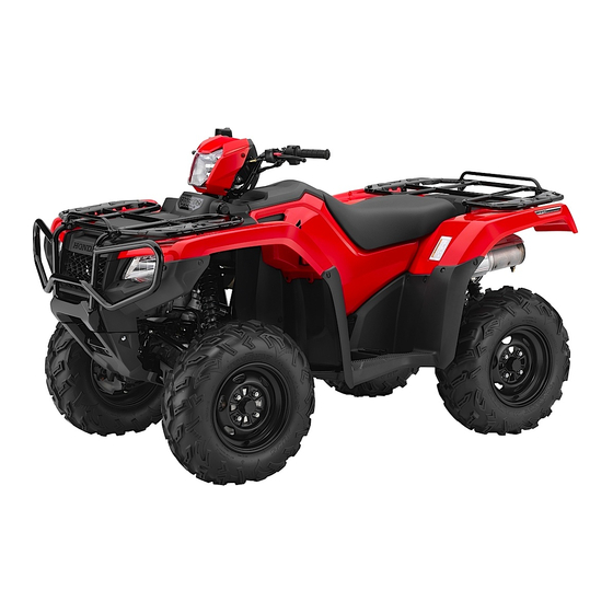
- Page 3 Honda TRX500FA6 4×4 with Power Steering TRX500FA7 4×4 with Power Steering/Aluminium Wheel OWNER’S MANUAL...
- Page 4 Introduction Congratulations on choosing your Honda ATV. Introduction When you own a Honda, you’re part of a worldwide family of satisfied customers — people who appreciate Honda’s reputation for building quality into every product. Your Honda was designed as a recreational ATV for off-road use by one rider only.
- Page 5 Introduction If you have any questions, or if you ever need special service or repairs, remember that your dealer knows your ATV best and is dedicated to your complete satisfaction. Happy riding! Introduction...
- Page 6 A Few Words About Safety Your safety, and the safety of others, is very important. And A Few Wo rds About Safety operating this ATV safely is an important responsibility. To help you make informed decisions about safety, we have provided operating procedures and other information on labels and in this manual.
- Page 7 A Few Words About Safety These signal words mean: You WILL be KILLED or DANGER SERIOUSLY HURT if you don't follow instructions. You CAN be KILLED or SERIOUSLY WARNING HURT if you don’t follow instructions. You CAN be HURT if you don’t CAUTION follow instructions.
- Page 8 Contents These pages give an overview of the contents of your owner’s Con ten ts manual. The first page of each section lists the topics covered in that section. ATV Safety ..................1 Important safety information you should know, plus a look at the safety related labels on your ATV.
-
Page 9: Table Of Contents
Contents Servicing Your Honda ............115 Why your ATV needs regular maintenance, what you need to know before servicing your Honda, an owner maintenance schedule, and instructions for specific maintenance and adjustment items. Tips ..................205 How to store and transport your ATV and how to be an environmentally responsible rider. - Page 10 Contents...
-
Page 11: Atv Safety
ATV Safety This section presents some of the most important information and ATV Safety recommendations to help you ride your ATV safely. Please take a few moments to read these pages. This section also includes information about the location of safety labels on your ATV. Important Safety Information............ - Page 12 Important Safety Information Your ATV can provide many years of service and pleasure if you take responsibility for your own safety and understand the challenges you can meet while riding. There is much that you can do to protect yourself when you ride. You’ll find many helpful recommendations throughout this manual.
- Page 13 Important Safety Information Ride Off-road Only Your ATV is designed and manufactured for off-road use only. The tyres are not made for pavement, and the ATV does not have turn signals and other features required for use on public roads. If you need to cross a paved or public road, get off and walk your ATV across.
- Page 14 So don’t drink and ride, and don’t let your friends drink and ride either. Keep Your Honda in Safe Condition It’s important to keep your ATV properly maintained and in safe riding condition. Having a breakdown can be difficult, especially if you are stranded off-road far from your base.
- Page 15 Safety Labels Your ATV comes with several labels containing important safety information. Anyone who rides the vehicle should read and understand this information before riding. The labels should be considered permanent parts of the vehicle. If a label comes off or becomes hard to read, contact your dealer for replacements.
- Page 16 Safety Labels WARNING Improper ATV use can result in SEVERE INJURY or DEATH ALWAYS USE NEVER USE NEVER CARRY NEVER USE AN APPROVED ON PUBLIC PASSENGERS WITH DRUGS HELMET AND ROADS OR ALCOHOL PROTECTIVE GEAR NEVER operate: without proper training or instruction at speeds too fast for your skills or the conditions on public roads - a collision can occur with another vehicle...
- Page 17 Safety Labels Improper tire pressure or overloading can cause loss of control. Loss of control can result in severe injury or death. Cold tire pressure : Front : 4.4psi (30kPa) Rear : 4.4psi (30kPa) Maximum weight capacity : 573lbs. (260kg) WARNING Overloading this ATV or carrying cargo improperly can change handling,stability...
- Page 18 Safety Labels BRAKING INFORMATION With four-wheel drive, operating any brake control causes braking at both the front and rear wheels. NEVER ride as a passenger. For detailed braking information, refer to the Owner's Manual. Passengers can cause a loss of control, resulting in SEVERE INJURY or DEATH.
-
Page 19: Instruments & Controls
Instruments & Controls This section shows the location of all indicators and controls you Inst ruments & Contro ls would normally use before or while riding your ATV. The items listed on this page are described in this section. Instructions for other components are presented in other sections of this manual where they will be most useful. - Page 20 Instruments & Controls Controls & Features ..............35 Ignition Switch................. 35 Range Select Lever..............36 4WD Switch ................37 Front Differential Lock and Speed Limiter Over-Ride (Differential Lock Switch and Start/Over Ride Button)......... 38 Start/Over Ride Button ............. 41 Engine Stop Switch ..............42 Headlight Switch ..............
-
Page 21: Operation Component Locations
Operation Component Locations rear brake lever/ headlight switch parking brake lever headlight differential lock switch dimmer switch P/R lever 4WD switch front brake lever gearshift ignition throttle lever switches switch horn button engine stop switch start/over ride button range select lever drive mode select switch Instruments &... - Page 22 Operation Component Locations rear cargo rack front cargo rack flag pole bracket rear brake pedal recoil starter Instruments & Controls...
- Page 23 Operation Component Locations accessory socket utility box storage compartment trailer hitch Instruments & Controls...
-
Page 24: Indicators & Displays
Indicators & Displays The indicators and displays on your ATV keep you informed, alert you to possible problems, and make your riding safer and more enjoyable. Refer to the indicators frequently. Their functions are described on the following pages. (1) neutral indicator (6) PS (Electric Power Steering) (2) reverse indicator indicator... - Page 25 Indicators & Displays Lamp Check Initial lamp check: The indicators come on for a few seconds and then go off when you turn the ignition switch to ON (q). The PS (Electric Power Steering) indicator comes back on and remains on until the engine is started after initial lamp check. The high coolant temperature indicator and PGM-FI indicator come back on for a few seconds and then go off after initial lamp check.
- Page 26 Indicators & Displays Display Check When the ignition switch is turned on, the multi-function display (1) will temporarily show all the modes and digital segments and initial message. So you can make sure the liquid crystal display is functioning properly. The displays are identified in the table on page 18 with the words: Display Check.
- Page 27 Indicators & Displays Neutral indicator Lights when the transmission is in neutral. Lamp Check. Reverse Lights when the transmission is in indicator reverse. Lamp Check. Differential lock Lights when the front differential lock indicator mode is engaged. Should also light for a few seconds and go off when the ignition switch is turned on, and then come back on and remain on until the...
- Page 28 Indicators & Displays Multi-function The display includes the following display functions. Display Check 4WD indicator Shows when the 4WD drive mode is engaged. If the indicator blinks with the differential lock indicator when there is any abnormality in the front final gear system.
- Page 29 Indicators & Displays Mode select Selects display in the lower parts button of multi-function display. Adjusts the digital clock (page 27). Changes the speed and mileage units (page 22). Resets the tripmeter to zero (0) (page 28). This button also used to reset the maintenance tripmeter and maintenance hour meter (page 34).
-
Page 30: Multi-Function Display
Indicators & Displays Multi-function Display The multi-function display (1) includes the following functions: 4WD indicator Odometer Gear position indicator Tripmeter LOW indicator Coolant temperature gauge Speedometer Hour meter Maintenance minder indicator Maintenance tripmeter Fuel gauge Maintenance hour meter Digital clock (1) multi-function display (6) lower part of the multi-function display... - Page 31 Indicators & Displays Each time you press the mode select button, mode will change as shown in the illustration. Fuel gauge (page 25) Digital clock (page 27) Odometer (page 28) Hour meter (page 31) Tripmeter (page 28) Maintenance tripmeter (page 32) Coolant temperature gauge (page 29) Maintenance hour...
-
Page 32: Speed And Mileage Unit Changing
Indicators & Displays Speed and Mileage Unit Changing The speedometer, odometer, tripmeter, and maintenance tripmeter show in either “MPH” and “MILE” or “KM/H” and “KM”. To change the speed and mileage units, press and hold the mode select button (1) for more than 5 seconds in the odometer mode (page 21) with the ATV stopped. -
Page 33: Low Indicator
Indicators & Displays LOW Indicator The LOW indicator (1) will be displayed when low (L) range is engaged with the ignition switch in the ON (q) position (page 94). (1) LOW indicator Instruments & Controls... -
Page 34: Gear Position Indicator
Indicators & Displays Gear Position Indicator The gear position indicator (1) shows the gear position when the ignition switch is in the ON (q) position. AUTO (automatic shift mode) The indicator displays N for neutral, R for reverse, and D for drive. ESP (manual shift mode) The indicator displays N for neutral, R for reverse, and 1 –... -
Page 35: Fuel Gauge
Indicators & Displays Fuel Gauge The fuel gauge (1) shows the approximate fuel supply available with the fuel mark (2). The fuel tank capacity is: 14.7 ℓ (3.88 US gal, 3.23 Imp gal) (1) fuel gauge (2) fuel mark Regardless of what mode the display is in, when the fuel level reaches 1st segment (3), the display will automatically switch to the fuel gauge display. - Page 36 Indicators & Displays (4) “E _ _ _ _ _ F” (5) “LO FUEL” When the fuel gauge show “E _ _ _ _ _ F” (4) and “LO FUEL” (5) blink 3 times alternately and fuel mark blinks, you should refuel as soon as possible.
-
Page 37: Digital Clock
Indicators & Displays Digital Clock The digital clock (1) shows time with the clock mark (2) when the ignition switch is ON (q). (1) digital clock (3) mode select button (2) clock mark To adjust the time, proceed as follows: 1. -
Page 38: Odometer
Indicators & Displays Odometer The odometer (1) registers total distance traveled in mileage while the ignition switch is ON (q) with the “ODO” mark (2). The odometer locks at 999,999 when the read-out exceeds 999,999. (1) odometer (2) “ODO” mark Tripmeter The tripmeter (1) shows mileage per trip since you last reset the tripmeter while the ignition switch is ON (q) with the “TRIP”... -
Page 39: Coolant Temperature Gauge
Indicators & Displays Coolant Temperature Gauge The coolant temperature gauge (1) shows coolant temperature with the coolant temperature mark (2) while the ignition switch is ON (q). The normal operating temperature range is within the section between the 1st segment (3) and 4th segment (4). When coolant temperature is low, the coolant temperature gauge will display “Lo”... - Page 40 Indicators & Displays When the coolant is over specified temperature, the 5th segment (6) appears and the high coolant temperature indicator (7) lights. If this occurs, stop the engine and check the reserve tank coolant level. Read pages 229 – 230 and do not ride the ATV until the problem has been corrected.
-
Page 41: Hour Meter
Indicators & Displays Hour meter The hour meter (1) shows accumulated hours while the ignition switch is ON (q) with the hour meter mark (2). The hour meter provides accurate service period information for initial and regular maintenance. The hour meter locks at 99,999.9 when the read-out exceeds 99,999.9. -
Page 42: Maintenance Tripmeter/Maintenance Hour Meter
Indicators & Displays Maintenance Tripmeter/Maintenance Hour meter The maintenance tripmeter (1) shows mileage to maintenance while the ignition switch is ON (q) with the maintenance minder indicator (2). The maintenance hour meter (3) shows remaining time to maintenance while the ignition switch is ON (q) with the maintenance minder indicator. - Page 43 Indicators & Displays Maintenance Minder Indicators: Initial Maintenance Appears at 150 km (100 miles) or 20 operating hours, whichever comes first. Regular Maintenance Interval 1 Appears 1,000 km (600 miles) or 100 operating hours after the Initial Maintenance or Regular Maintenance Interval 2 is performed and maintenance minder is reset, whichever comes first in the maintenance schedule.
- Page 44 Indicators & Displays Reset the maintenance tripmeter/maintenance hour meter after maintenances. To reset the maintenance tripmeter/maintenance hour meter, proceed as follows: Press and hold the mode select button (5) and turn the ignition switch (6) to ON (q). The maintenance minder indicator will appear, then it will blinks twice, and the multi-function display will temporarily show all the modes and digital segments.
-
Page 45: Controls & Features
Controls & Features Ignition Switch The ignition switch (1) is used for starting and stopping the engine (page 82). Insert the key and turn it to the right for the ON (q) position. The ignition switch is also used to reset the maintenance tripmeter/ maintenance hour meter (page 34). -
Page 46: Range Select Lever
Controls & Features Range Select Lever The range select lever (1) has two positions: Drive (D), Low (L). See Shifting Gears, page 94. LEFT SIDE OF FUEL TANK (1) range select lever Instruments & Controls... -
Page 47: 4Wd Switch
Controls & Features 4WD Switch Your ATV is equipped with a 4WD switch (1), which permits a choice between the “2WD” and “4WD” drive modes. Select a drive mode that’s suitable for your riding. Keep both hands on the handlebar while machine is in motion and come to a complete stop before using the 4WD switch. -
Page 48: Front Differential Lock And Speed Limiter Over-Ride (Differential Lock Switch And Start/Over Ride Button)
Controls & Features Front Differential Lock and Speed Limiter Over-Ride (Differential Lock Switch and Start/Over Ride Button) Your ATV is equipped with a front differential lock feature that includes a speed limiter and speed limiter over-ride. This system is designed to provide maximum use of available traction to help you escape from situations where the vehicle might otherwise become stuck, in the mud for example. - Page 49 Controls & Features To select the front differential lock mode: When the 4WD mode is engaged, reduce the speed of your ATV to below 16 km/h (10 mph) and slide the differential lock switch (1) over the 4WD switch. The differential lock indicator (2) will flash fast and the front differential locking process begins.
- Page 50 Controls & Features To activate the speed limiter over-ride mode: Push the start/over ride button (3) when the front differential lock mode is activated. LEFT HANDLEBAR (3) start/over ride button Front final gear system failure: The differential lock indicator and 4WD indicator (4) will both flash when there is any abnormality in the front final gear system.
-
Page 51: Start/Over Ride Button
Controls & Features Start/Over Ride Button LEFT HANDLEBAR (1) start/over ride button START or SPEED LIMITER OVER-RIDE MODE The start/over ride button (1) is used for starting the engine and activate the speed limiter over-ride mode. Pushing the button in starts the engine. See Starting Procedure, page 84. -
Page 52: Engine Stop Switch
Controls & Features Engine Stop Switch LEFT HANDLEBAR (1) engine stop switch r OFF e RUN The engine stop switch (1) is used to stop the engine in an emergency. To operate, slide the switch to the OFF (r) position. The switch must be in the RUN (e) position to start the engine, and it should normally remain in the RUN (e) position even when the engine is OFF. -
Page 53: Headlight Switch
Controls & Features Headlight Switch LEFT HANDLEBAR (1) headlight switch y ON t OFF (2) headlight dimmer switch u HI i LO (3) horn button The headlight switch (1) is used to turn the headlights and assist headlight ON (y) or OFF (t). The assist headlight turns on only when the headlight dimmer switch (2) is in the HI (u) position. -
Page 54: Recoil Starter
Controls & Features Recoil Starter RIGHT SIDE (1) recoil starter The recoil starter (1) is used to start the engine when the battery is low. See Using the Recoil Starter, page 87. Instruments & Controls... -
Page 55: Throttle Lever
Controls & Features Throttle Lever RIGHT HANDLEBAR (1) throttle lever (A) to open the throttle The throttle controls engine rpm (speed). To increase engine rpm, press the throttle lever (1) with your thumb. To reduce engine rpm, release pressure on the throttle lever. The throttle will automatically return to the closed position (engine idle) when you remove your thumb. -
Page 56: Drive Mode Select Switch
Controls & Features Drive Mode Select Switch The drive mode select switch (1) has two positions: AUTO (automatic shift mode) and ESP (manual shift mode). See Shifting Gears, page 89. RIGHT HANDLEBAR (1) drive mode select switch Instruments & Controls... -
Page 57: Gearshift Switch
Controls & Features Gearshift Switch AUTO (automatic shift mode): These gearshift switches [upshift switch (1) and downshift switch (2)] are used to select the drive (D), neutral (N) and reverse (R). See Shifting Gears, page 88 and Riding in Reverse, page 95. ESP (manual shift mode): These gearshift switches are used to select the next higher or lower gear in the transmission. -
Page 58: Front Brake Lever
Controls & Features Front Brake Lever The front brake lever is used to slow or stop your ATV. To operate, pull the lever. For information on braking techniques, see page 97. Rear Brake Lever/Parking Brake Lever The rear brake lever/parking brake lever is used to slow or stop your ATV. -
Page 59: Parking Brake/Reverse Lever (P/R Lever)
Controls & Features Parking Brake/Reverse Lever (P/R Lever) LEFT HANDLEBAR (1) P/R lever (2) rear brake lever/parking brake lever The P/R lever (1) on the rear brake lever/parking brake lever (2) is used to apply the parking brake or to shift the transmission into reverse. - Page 60 Controls & Features To apply the parking brake: Bring the vehicle to a complete stop, then make sure the transmission is in neutral. Squeeze the rear brake lever/parking brake lever (1), then rotate the P/R lever (2) clockwise until it engages the slot on the rear brake lever/parking brake lever bracket.
-
Page 61: Flag Pole Bracket
Controls & Features Flag Pole Bracket RIGHT REAR (1) flag pole bracket Flag poles are optional equipment available from your dealer. To mount a pole in the bracket (1), follow the instructions that come with the flag pole kit. Flag poles are required in some riding areas. Check local regulations before riding. -
Page 62: Trailer Hitch
Controls & Features Trailer Hitch REAR (1) trailer hitch (2) ball The trailer hitch (1) is located on the rear frame. To use the hitch, you’ll need a proper size ball (2) as specified by the trailer manufacturer. To attach the ball and properly hook up a trailer, follow the trailer manufacturer’s instructions. -
Page 63: Accessory Socket
Controls & Features Accessory Socket LEFT FRONT (1) accessory socket (3) accessory socket cap (2) front centre cover The accessory socket (1) is attached to the left side of the front centre cover (2). You can use the accessory socket to power a trouble light, spotlight, CB radio, or cell phone, etc. - Page 64 Controls & Features Be sure the engine is on and the headlights are turned off before using the accessory socket, otherwise you may drain the battery. The accessory socket’s rated capacity is DC 12 V, 120 Watts (10 A) or less. If you exceed this limit, you may blow a fuse. See If a Fuse Blows, page 231.
-
Page 65: Utility Box
Controls & Features Utility Box The utility box (1) is located on the left side of the front fender. You may store small, lightweight items in the box. To open: Pull up the front of the utility box cover (2). To close: Push down the front of the utility box cover until it locks in place. -
Page 66: Storage Compartment
Controls & Features Storage Compartment The storage compartment (1) is located below the rear cargo rack (2). To open the compartment, unhook the rubber strap (3). Be careful not to flood this area when washing your ATV. REAR (1) storage compartment (3) rubber strap (2) rear cargo rack Instruments &... -
Page 67: Ps (Electric Power Steering)
Controls & Features PS (Electric Power Steering) This ATV is equipped with an electronically controlled, electric- power-assisted steering system. While the engine is running, the PS (Electric Power Steering) system provides power from the electric motor, which helps you to turn the ATV’s handlebar more easily. - Page 68 Instruments & Controls...
-
Page 69: Before Riding
Before Riding Before each ride, you need to make sure you and your Honda are Befor e Riding both ready to ride. To help get you prepared, this section discusses how to evaluate your riding readiness, what items you should check on your ATV, and adjustments to make for your comfort, convenience, or safety. -
Page 70: Are You Ready To Ride
Are You Ready to Ride? Before you ride your ATV for the first time, we urge you to: • Read this owner’s manual and the labels on your ATV carefully. • Make sure you understand all the safety messages. • Know how to operate all the controls. Before each ride, be sure: •... - Page 71 Are You Ready to Ride? An open-face helmet offers some protection, but a full-face helmet offers more. Always wear a face shield or goggles to protect your eyes and help your vision. WARNING WARNING Operating this ATV without wearing an approved motorcycle helmet, eye protection, and protective clothing could increase your chances of severe injury or death in the event...
-
Page 72: Rider Training
Beginning and inexperienced operators should complete the certified training course offered by Honda. They should then regularly practice the skills learned in the course and the operating techniques described in the owner’s manual. -
Page 73: Age Recommendation
Are You Ready to Ride? Age Recommendation The minimum recommended age for this ATV model is 16. For safety, never let children under 16 years old operate this vehicle. WARNING WARNING A child using an ATV that is not recommended for their age could lose vehicle control while riding, resulting in severe injury or death. -
Page 74: No Alcohol Or Drugs
Are You Ready to Ride? No Alcohol or Drugs Alcohol, drugs and ATVs don’t mix. Even a small amount of alcohol can impair your ability to operate an ATV safely. Likewise, drugs — even if prescribed by a physician — can be dangerous while operating an ATV. -
Page 75: Is Your Atv Ready To Ride
Is Your ATV Ready to Ride? Before each ride, it’s important to inspect your ATV and make sure any problem you find is corrected. A pre-ride inspection is a must, not only for safety, but because having a breakdown, or even a flat tyre, can be a major inconvenience. - Page 76 Is Your ATV Ready to Ride? Fuel Check the level and add fuel (page 135) if needed. Also make sure the fuel fill cap is securely fastened. Check for leaks. Tyres Use a gauge to check the air pressure. Adjust if needed.
- Page 77 Is Your ATV Ready to Ride? Lights Make sure the headlights, brakelight and taillight are working properly. If you are carrying cargo, also check the following: Loading Limits Make sure you do not exceed the load limits (page 70). Cargo Check that all cargo is secure.
- Page 78 Is Your ATV Ready to Ride? Headlights and Check for proper function (page 43). Headlight Dimmer Switch Engine Stop Switch Check for proper function (page 42). Steering Check that the wheels turn properly as you steer the handlebar. Move the handlebar right and left and check that there is no excessive backlash.
-
Page 79: Load Limits & Guidelines
Load Limits & Guidelines Your Honda was designed as a rider-only ATV. It was not designed to carry a passenger. It can carry cargo on the cargo racks, however, carrying cargo anywhere else or carrying a passenger could interfere with your balance and control of the ATV. -
Page 80: Load Limits
Load Limits & Guidelines Load Limits Following are the load limits for your ATV: There are limits to how much weight can be carried on your ATV and be pulled in a trailer. The following load limits apply to standard equipment only. Modifying your ATV, using non-standard equipment, or riding on terrain that is not flat and smooth could further reduce these limits. -
Page 81: Loading Guidelines
Load Limits & Guidelines Loading Guidelines Carrying cargo or pulling a trailer will affect how your ATV handles and greatly reduce its ability in accelerating, braking and making turns and other maneuvers. Be sure to observe the weight limits and follow these guidelines: •... -
Page 82: Accessories & Modifications
We strongly recommend that you use only Honda Genuine Accessories that have been specifically designed and tested for your ATV. Because Honda cannot test all other accessories, you must be personally responsible for proper selection, installation, and use of non-Honda accessories. -
Page 83: Modifications
Accessories & Modifications Modifications We strongly advise you not to remove any original equipment or modify your ATV in any way that would change its design or operation. Such changes could seriously impair your ATV’s handling, stability, and braking, making it unsafe to ride. Removing or modifying your lights, exhaust system, emission control system, or other equipment can also make your ATV illegal. - Page 84 Before Riding...
-
Page 85: Basic Operation & Riding
Basic Operation & Riding This section gives basic riding instructions, including how to start and Basic Operation & R iding stop your engine, and how to use the throttle and brakes. It also provides important information on riding with cargo. To protect your new engine and enjoy optimum performance and service life, refer to Break-in Guidelines (page 248). - Page 86 Basic Operation & Riding Braking..................97 Riding Your ATV................. 99 Making Turns ................99 Skidding or Sliding ..............101 Riding Up Hills ............... 102 Riding Down Hills ..............106 Crossing or Turning on Hills or Slopes ........107 Riding Over Obstacles ............109 Riding Through Water ............
-
Page 87: Safe Riding Precautions
Safe Riding Precautions Before riding your ATV for the first time, please review the ATV Safety section beginning on page 1, and the Before Riding section beginning on page 59. Even if you have ridden other ATVs, take time to become familiar with how this ATV works and handles. -
Page 88: Keep Hands And Feet On Controls
Safe Riding Precautions You should never ride your ATV on public streets, roads or highways, even if they are not paved. Drivers of street vehicles may have difficulty seeing and avoiding you, which could lead to a collision. In many states it is illegal to operate ATVs on public streets, roads and highways. -
Page 89: Control Speed
Safe Riding Precautions Control Speed Riding at excessive speed increases the chance of a crash. In choosing a proper speed, you need to consider the capability of your vehicle, the terrain, visibility and other operating conditions, plus your own skills and experience. WARNING WARNING Operating this ATV at excessive speeds... -
Page 90: Use Care On Unfamiliar Or Rough Terrain
Safe Riding Precautions Use Care on Unfamiliar or Rough Terrain Before riding in a new area, always check the terrain thoroughly. Don’t ride fast on unfamiliar terrain or when visibility is limited. (It’s sometimes difficult to see obstructions like hidden rocks, bumps, or holes in time to react.) WARNING WARNING... -
Page 91: Do Not Perform Stunts
Safe Riding Precautions Never ride past the limit of visibility. Maintain a safe distance between your ATV and other off-road vehicles. Always exercise caution, and use extra care on rough, slippery and loose terrain. WARNING WARNING Failure to use extra care when operating on excessively rough, slippery or loose terrain could cause loss of traction or vehicle control, which could result in an accident, including an... -
Page 92: Starting & Stopping The Engine
Starting & Stopping the Engine Always follow the proper starting procedure described below. For your safety, avoid starting or operating the engine in an enclosed area such as a garage. Your ATV’s exhaust contains poisonous carbon monoxide gas which can collect rapidly in an enclosed area and cause illness or death. -
Page 93: Preparation
Starting & Stopping the Engine Preparation (1) ignition switch (3) engine stop switch (2) neutral indicator 1. Before starting, make sure the vehicle is on a level surface and lock the parking brake (page 50). 2. Turn the ignition switch (1) to ON (q). Confirm the following: •... -
Page 94: Starting Procedure
Starting & Stopping the Engine Starting Procedure This ATV is fuel-injected engine with an automatic choke. Follow the procedure indicated below. Any Air Temperature • Press the start/over ride button with the throttle completely closed. The engine will not start if the throttle is fully open (because the electronic control module cuts off the fuel supply). -
Page 95: Flooded Engine
Starting & Stopping the Engine Flooded Engine If the engine fails to start after repeated attempts, it may be flooded with excess fuel. To clear a flooded engine: 1. Leave the engine stop switch set to RUN (e). 2. Open the throttle fully. 3. -
Page 96: Stalled Engine
Starting & Stopping the Engine Stalled Engine You can restart the engine while the vehicle is stopped by squeezing the front brake lever and pressing the start/over ride button. Do not press the throttle lever while starting in gear. The engine will not start if the throttle is fully open (because the electronic control module cuts off the fuel supply). -
Page 97: Using The Recoil Starter
Starting & Stopping the Engine Using the Recoil Starter The recoil starter is used to start the engine when the battery is low. To operate the recoil starter: 1. Turn the ignition switch to ON and the engine stop switch to RUN. 2. -
Page 98: Shifting Gears
Shifting Gears Your ATV has two shift modes: AUTO (automatic shift mode) and ESP (manual shift mode). You can select the desired shift mode with the drive mode select switch. AUTO (automatic shift mode): Use this mode for everyday riding. The transmission automatically shifts to keep the engine at the best speed for riding condition. - Page 99 Shifting Gears Drive mode select (AUTO/ESP) The drive mode select switch (1) is located on the right handlebar. To select the drive mode, release the throttle, then slide the drive mode select switch to the desired position. With the throttle fully closed, the drive mode can be changed while riding.
- Page 100 Shifting Gears To select a forward gear (D or 1) from neutral (N), press the upshift switch (2) once. • In AUTO (automatic shift mode) the gear position indicator shows “D” • In ESP (manual shift mode) the gear position indicator shows “1” To select reverse (R) from neutral (N), use the P/R lever and press the downshift switch (3) once.
- Page 101 Shifting Gears Driving in ESP (manual shift mode). After starting the engine and letting it warm up, follow these procedures: 1. With the transmission in neutral, release the parking brake (page 50), but continue to squeeze the rear brake lever/parking brake lever.
- Page 102 Shifting Gears The transmission cannot be upshifted from neutral to 1st gear when the engine speed is above 2,300 min (rpm) or the ground speed is above 3 km/h (2 mph). The transmission cannot be downshifted from 1st gear to neutral when the ground speed is above 1.5 km/h (1 mph) or engine speed is above 2,300 min (rpm).
- Page 103 Shifting Gears Learning when to shift gears comes with experience. Keep the following tips in mind: • As a general rule, shift while moving in a straight line. • Close the throttle completely before shifting. Improper shifting may damage the engine, transmission, and drivetrain. •...
- Page 104 Shifting Gears Your ATV has two gear ranges: Drive (D), and Low (L). The range select lever (4) is located on the left side of the fuel tank. To select a transmission range, bring the ATV to a complete stop. NOTICE If the range select lever is moved while the vehicle is moving, the sub-transmission may be damaged.
-
Page 105: Riding In Reverse
Riding in Reverse If you need to ride in reverse, make sure the area behind you is clear and only operate the ATV at low speed. WARNING WARNING Improperly operating in reverse could cause you to hit an obstacle or person behind you, resulting in serious injury. - Page 106 Riding in Reverse NOTICE Your ATV may be equipped with a reverse speed limiter, which helps the vehicle to maintain a safe speed while riding in reverse gear. 6. Release the rear brake lever/parking brake lever. 7. Open the throttle gradually and ride slowly. Do not open the throttle suddenly or make abrupt turns.
-
Page 107: Braking
Braking Your ATV is equipped with disc brakes on both front wheels which are hydraulically activated by operating the front brake lever. The single disc brake of the rear drivetrain is hydraulically activated by pressing down on the brake pedal and mechanically activated by operating the rear brake lever/parking brake lever. - Page 108 Braking When possible, reduce your speed or complete braking before entering a turn. Avoid braking or closing the throttle quickly while turning. Either action may cause one or more wheels to slip and reduce your control of your ATV. Your ability to brake in a turn and to brake hard in an emergency situation are important riding skills.
-
Page 109: Riding Your Atv
Riding Your ATV Making Turns Learn how to turn your ATV properly. Practice the techniques outlined in this section on level ground and at low speeds until you are confident in making turns. WARNING WARNING Turning improperly can make the ATV go out of control, causing a collision or overturn. - Page 110 Riding Your ATV Lean your body to the inside of a turn and forward. To make a turn on level ground: Steer the handlebar and lean your body toward the inside of the turn. Leaning helps balance the vehicle, and it feels more comfortable. Leaning into a turn is an important technique to master in riding an ATV.
-
Page 111: Skidding Or Sliding
Riding Your ATV Skidding or Sliding The terrain surface can be a major factor affecting turns. Skidding during a turn is more likely to occur on slippery surfaces, such as snow, ice, mud and loose gravel. If you skid on ice, you may lose all directional control. -
Page 112: Riding Up Hills
Riding Your ATV Riding Up Hills The ATV’s ability to safely climb hills largely depends on the rider’s skill and judgement. Begin by practicing on smooth, gentle slopes. As you gain experience, you’ll learn the hazards and your own limitations. You may then proceed to ride on more difficult terrain. However, you must be able to decide which hills or hazards might cause the ATV to overturn. - Page 113 Riding Your ATV Shift weight forward when climbing hills. • Always check the terrain carefully before you start up any hill. • Never climb hills with excessively slippery or loose surfaces. • To climb a hill, take a running start in an appropriate gear and speed for the conditions.
- Page 114 Riding Your ATV Stalling the ATV and/or Rolling Backwards: If you incorrectly estimate climbing capability or terrain conditions, the ATV may not have enough power or traction to continue uphill. If this happens, the ATV can stall and/or roll backwards. WARNING WARNING Stalling, rolling backwards or improperly...
- Page 115 Riding Your ATV What to do after the ATV has stalled or rolled backwards: If the hill is too steep or too slippery, or if you have any doubt whether you can safely walk the ATV back down the hill, leave the vehicle where it is and get help.
-
Page 116: Riding Down Hills
Riding Your ATV Riding Down Hills It’s usually advisable to descend hills with the ATV pointed straight downhill. Avoid angles that would cause the vehicle to lean sharply to one side. WARNING WARNING Going down a hill improperly could cause loss of control or cause the ATV to overturn. -
Page 117: Crossing Or Turning On Hills Or Slopes
Riding Your ATV When you’ve selected a safe downhill path, shift into a lower gear, shift your weight back with your arms extended and braced against the handlebar, then go down slowly with the throttle closed. Use mainly the rear brake to control speed. Avoid using either the front brake or rear brake hard or abruptly when riding down hills. - Page 118 Riding Your ATV Crossing Hills or Slopes • To maintain balance and stability when riding across a slope, you need to shift weight toward the uphill side of the vehicle. To do this, move your body off the centre of the seat and lean toward the uphill side.
-
Page 119: Riding Over Obstacles
Riding Your ATV Riding Over Obstacles Before operating in a new area, check for obstacles. Watch out for bumps, rain ruts, potholes and other obstacles in the terrain. When you approach any obstacle, reduce your speed and be prepared to stop. -
Page 120: Riding Through Water
Riding Your ATV Riding Through Water Your ATV is designed to travel through water up to approximately 254 mm (10 in) deep. Before crossing a stream, make sure the water is not too deep or flowing too fast. WARNING WARNING The ATV tyres have some ability to float. - Page 121 Riding Your ATV 1. Choose a path where both banks have gradual slopes. 2. Proceed through the water at a slow, steady speed. 3. Watch out for submerged obstacles and slippery rocks. 4. Avoid getting the spark plug or air cleaner wet, as this would cause the engine to stop.
-
Page 122: Parking
Parking 1. Look for level parking area. Make sure the ground surface is firm. 2. After bringing your ATV to a stop, hold the brakes while you shift into neutral. 3. Set the parking brake (page 50). 4. Turn the ignition switch OFF (w). If it is necessary to start the engine when your ATV in gear and is stopped on a grade, rock the vehicle back and forth to allow shifting the transmission into neutral. - Page 123 Parking Parking on a Steep Incline or a Loose or Slippery Surface If you must park your ATV on a steep incline or loose or slippery surface, use the following procedure: 1. While holding the brakes, set the parking brake. 2.
- Page 124 Basic Operation & Riding...
-
Page 125: Servicing Your Honda
Maintenance Schedule for required service and step-by-step instructions for specific maintenance tasks. You’ll also find important safety precautions, information on fuels and oils, and tips for keeping your Honda looking good. For information about replacing fuses, see page 231. Before You Service Your Honda The Importance of Maintenance .......... - Page 126 Servicing Your Honda Service Procedures Fluids & Filters Fuel ..................134 Engine Oil & Filter ..............137 Rear Final Gear Oil..............147 Front Final Gear Oil..............150 Coolant ..................152 Air Cleaner ................160 Engine Throttle ..................166 Reverse Inhibitor System ............168 Spark Plug ................
-
Page 127: The Importance Of Maintenance
Before You S ervice Your Honda The Importance of Maintenance A well-maintained ATV is essential for safe, economical, and trouble- free riding. It will also help reduce air pollution. Careful pre-ride inspections and good maintenance are especially important because your ATV is designed to be ridden over rough off-road terrain. -
Page 128: Maintenance Safety
Other tasks that are more difficult and require special tools are best performed by professionals. Removing the wheels should normally be handled only by a Honda technician or other qualified mechanic. Instructions are included in this manual only to assist in emergency service. -
Page 129: Important Safety Precautions
Keep cigarettes, sparks, and flames away from all fuel-related parts. Remember that your Honda dealer knows your ATV best and is fully equipped to maintain and repair it. To ensure the best quality and reliability, use only new Honda Genuine Parts or other equivalents for repair and replacement. -
Page 130: Maintenance Schedule
Procedures for such items in this schedule are provided in an official Honda Shop Manual available for purchase. If you do not feel capable of performing a given task or need assistance, remember that your Honda dealer knows your ATV best and is fully equipped to maintain and repair it. - Page 131 Should be serviced by your dealer, unless you have the proper tools and service data, and are mechanically qualified. Refer to the official Honda Shop Manual. ** In the interest of safety, we recommend these items be serviced only by your dealer.
- Page 132 — RADIATOR COOLANT NOTE 3 COOLING SYSTEM NOTE 2 — * Should be serviced by your dealer, unless you have the proper tools and service data, and are mechanically qualified. Refer to the official Honda Shop Manual. Servicing Your Honda...
- Page 133 * Should be serviced by your dealer, unless you have the proper tools and service data, and are mechanically qualified. Refer to the official Honda Shop Manual. ** In the interest of safety, we recommend these items be serviced only by your dealer.
-
Page 134: Maintenance Record
12 or 200 3,000 (1,800) or 18 or 300 4,000 (2,400) or 24 or 400 5,000 (3,000) or 30 or 500 6,000 (3,600) or 36 or 600 7,000 (4,200) or 42 or 700 8,000 (4,800) or 48 or 800 Servicing Your Honda... -
Page 135: Maintenance Component Locations
Maintenance Component Se rvice Preparations Locations reverse assist lever front brake fluid reservoir P/R lever front brake lever rear brake lever/ fuel fill cap throttle lever parking brake lever Servicing Your Honda... - Page 136 Servicing Your Honda...
- Page 137 Servicing Your Honda...
-
Page 138: Tool Kit
10 × 12 mm open end wrench 14 × 17 mm open end wrench spark plug wrench and handlebar pliers tool case 5 mm hex wrench REAR (1) tool kit (3) rubber band (2) gear change tool Servicing Your Honda... -
Page 139: Owner's Manual Storage
Be careful not to flood this area when washing your ATV. REAR FENDER COVER UNDERSIDE (1) owner’s manual (4) air pressure gauge (2) plastic document bag (5) 40 A spare fuse (3) rear fender cover (6) rubber band Servicing Your Honda... -
Page 140: Seat Removal
1. Insert the front prongs (3) into the backside of the tank cover (4) and hooks (5) on the frame, and press the studs (6) into the grommets (7). 2. Press down on the seat until locks. Servicing Your Honda... -
Page 141: Rear Fender Cover Removal
3. Firmly pull the studs (2) from the grommets (3). 4. Slide the rear fender cover (4) forward to disengage the tabs (5). 5. Remove the rear fender cover. Installation Install the rear fender cover in the reverse order of removal. Servicing Your Honda... -
Page 142: Tank Cover Assembly Removal
2. Carefully remove the right studs (1) and left studs from the grommets. 3. Remove the tank cover assembly (2) by releasing the right tabs (3) and left tabs from the slits. Installation Install the tank cover assembly in the reverse order of removal. Servicing Your Honda... -
Page 143: Clip Removal
1. Pull up the centre pin to release the lock. 2. Pull out the clip of the hole. Installation 1. Insert the clip into the hole. 2. Press down the centre pin securely to lock the clip. Servicing Your Honda... -
Page 144: Fuel
91 (or higher) Use only unleaded fuel in your Honda. If you ride your Honda in a country where leaded fuel might be available, take precautions to use only unleaded fuel. Your engine is designed to use any unleaded petrol that has a pump octane number (R + M)/2 of 86 or higher, or a research octane number of 91 or higher. - Page 145 When there is only one segment left in the fuel gauge (page 25), fuel will be low and you should refuel as soon as possible. Refuelling Procedure Refer to Safety Precautions on page 119. (1) fuel fill cap (2) lower edge of filler neck Servicing Your Honda...
- Page 146 • Stop the engine and keep heat, sparks and flame away. • Handle fuel only outdoors. • Wipe up spills immediately. 3. After refuelling, turn the fuel fill cap clockwise securely. If you replace the fuel fill cap, use only a Honda Genuine replacement part. Servicing Your Honda...
-
Page 147: Engine Oil & Filter
Change the engine oil as specified in the maintenance schedule on page 122. When running in very dusty conditions, oil changes should be performed more frequently than specified in the maintenance schedule. Servicing Your Honda... - Page 148 • Do not use API SH or higher oils displaying a circular API “energy conserving” or “resource conserving” service label on the container. They may affect lubrication and clutch performance. NOT RECOMMENDED RECOMMENDED • Do not use non-detergent, vegetable, or castor based racing oils. Servicing Your Honda...
- Page 149 The JASO T 903 standard is an index for engine oils for 4-stroke motorcycle engines. There are two classes: MA and MB. Oil conforming to the standard is labeled on the oil container. For example, the following label shows the MA classification. (1) oil code (2) oil classification Servicing Your Honda...
- Page 150 3. Stop the engine and wait for 2 – 3 minutes. 4. Remove the oil check lid (1) by disengaging the stud (2) from the grommet (3) and releasing the tabs (4) from the slits. LEFT SIDE (1) oil check lid (3) grommet (2) stud (4) tabs Servicing Your Honda...
- Page 151 The oil level should be between the upper level mark (6) and the lower level mark (7) on the dipstick. LEFT SIDE (5) dipstick (6) upper level mark (7) lower level mark (cont’d) Servicing Your Honda...
- Page 152 9. Install the tank cover assembly. 10. Install the seat. 11. Install the oil check lid. NOTICE Running the engine with an improper oil level can cause serious engine damage. RIGHT SIDE (8) engine oil fill cap Servicing Your Honda...
- Page 153 Changing Engine Oil & Filter Refer to Safety Precautions on page 119. Your ATV’s oil filter has very specific performance requirements. Use a new Honda Genuine oil filter specified for your model or a filter of equal quality. NOTICE Using the wrong oil filter may result in leaks or engine damage.
- Page 154 Engine Oil & Filter 2. Place an oil drain pan under the crankcase and remove the engine oil drain bolt (1) and sealing washer (2). UNDER ENGINE (1) engine oil drain bolt (2) sealing washer Servicing Your Honda...
- Page 155 (TOWARDS FILTER COVER)” mark (7) faces away from the engine, toward the oil filter cover. Use only the Honda Genuine oil filter or a filter of equivalent quality specified for your model. Using the wrong Honda filter or a non-Honda filter which is not of equivalent quality may cause engine damage.
- Page 156 6. Check that there are no oil leaks. 7. Install the tank cover assembly (page 132). 8. Install the seat (page 130). If a torque wrench is not used for installation, see your dealer as soon as possible to verify proper assembly. Servicing Your Honda...
-
Page 157: Rear Final Gear Oil
Oil Recommendation type hypoid gear oil viscosity (weight) SAE 80W-90 Changing Oil Refer to Safety Precautions on page 119. Change the oil with the rear final gear at normal operating temperature to assure complete and rapid draining. Servicing Your Honda... - Page 158 12 N·m (1.2 kgf·m, 9 lbf·ft) 5. Pour the drained oil into a suitable container and dispose of it in an approved manner (page 214). NOTICE Improper disposal of drained fluids is harmful to the environment. Servicing Your Honda...
- Page 159 7. Coat a new O-ring with grease and install it into the fill cap groove and tighten it to the specified torque: 12 N·m (1.2 kgf·m, 9 lbf·ft) REAR (1) oil drain bolt (4) sealing washer (2) oil fill cap (5) oil fill inspection hole (3) O-ring Servicing Your Honda...
-
Page 160: Front Final Gear Oil
Oil Recommendation type hypoid gear oil viscosity (weight) SAE 80W-90 Changing Oil Refer to Safety Precautions on page 119. Change the oil with the front final gear at normal operating temperature to assure complete and rapid draining. Servicing Your Honda... - Page 161 7. Coat a new O-ring with grease and install it into the fill cap groove and tighten it to the specified torque: 12 N·m (1.2 kgf·m, 9 lbf·ft) FRONT (1) oil drain bolt (4) sealing washer (2) oil fill cap (5) oil fill inspection hole (3) O-ring Servicing Your Honda...
-
Page 162: Coolant
The factory provides a 50/50 solution of antifreeze and water in this ATV. This coolant solution is recommended for most operating temperatures and provides good corrosion protection. Decreasing the concentration of antifreeze to less than 40% will not provide proper corrosion protection. Servicing Your Honda... - Page 163 (1). It should be between the UPPER (2) and LOWER (3) level marks. If the reserve tank is empty, or if coolant loss is excessive, check for leaks and see your dealer for repair. (cont’d) Servicing Your Honda...
- Page 164 5. Add coolant to the reserve tank as required to bring the coolant level to the UPPER level mark. FRONT (4) radiator cap lid (6) grommet (5) stud (7) reserve tank cap 6. After adding coolant, reinstall the reserve tank cap. 7. Install the radiator cap lid. Servicing Your Honda...
- Page 165 Refer to Safety Precautions on page 119. Coolant should be replaced by your dealer, unless you have the proper tools and service data, and are mechanically qualified. Refer to the official Honda Shop Manual. WARNING WARNING Removing the radiator cap while the engine is hot can cause the coolant to spray out, seriously scalding you.
- Page 166 20% of the radiator surface. Clean the radiator core after riding the ATV in mud. The left and centre radiator grill covers must be removed to clean the radiator core. Servicing Your Honda...
- Page 167 2. Remove the reserve tank (1) by removing the bolt (2) and clips (3) (page 133). 3. Release the hoses (4) from the guides. 4. Hold the reserve tank being careful not to spill the coolant. LEFT FRONT (1) reserve tank (3) clips (2) bolt (4) hoses (cont’d) Servicing Your Honda...
- Page 168 B (7), tab C (8), hook A (9) and hook B (10). LEFT FRONT (10) (3) clips (7) tab B (5) left radiator grill (8) tab C cover (9) hook A (6) tab A (10) hook B Servicing Your Honda...
- Page 169 8. Wash the radiator core (12) and radiator grill covers. NOTICE Do not apply pressured water directly to the radiator core. The pressured water can damage the radiator core. 9. Install the removed parts in reverse order of removal. Servicing Your Honda...
-
Page 170: Air Cleaner
Your dealer can help you determine the correct service interval for your riding conditions. Your ATV’s air cleaner has very specific performance requirements. Use a new Honda Genuine air cleaner specified for your model or an air cleaner of equal quality. NOTICE Using the wrong air cleaner may result in premature engine wear. - Page 171 1. Remove the seat (page 130). UNDER SEAT (1) spring hooks (3) air cleaner housing cover (2) retainer clips 2. Unlatch the spring hooks (1) and retainer clips (2). 3. Remove the air cleaner housing cover (3). (cont’d) Servicing Your Honda...
- Page 172 Gently squeeze out any excess oil. (To keep your hands dry, place the air cleaner in a clean plastic bag before spreading the oil into the air cleaner.) UNDER SEAT (4) screw (7) air cleaner (5) air cleaner assembly (8) air cleaner body (6) clamp Servicing Your Honda...
- Page 173 • Install the air cleaner housing cover with the FRONT mark (9) facing forward and fit the cut out of the tab (10) at the end of the air cleaner. UNDER SEAT (10) (10) (9) FRONT mark (10) tab Servicing Your Honda...
- Page 174 Air Cleaner Dust Cover UNDER SEAT (1) dust cover (2) breather joint Do not push the dust cover (1) too far into the breather joint (2). If the dust cover is dirty, clean it. Servicing Your Honda...
- Page 175 (3) air cleaner housing (2) clip 1. Remove the drain tube (1) by removing the clip (2) under the air cleaner housing (3). 2. Drain the deposits. 3. Reinstall the drain tube, securing it with the clip. Servicing Your Honda...
-
Page 176: Throttle
3. Turn the adjuster to obtain the correct freeplay. 4. Tighten the lock nut and reinstall the sleeve. 5. After adjustment, check for smooth operation of the throttle lever from fully closed to fully open in all steering positions. Servicing Your Honda... - Page 177 If the cable is kinked or chafed, have it replaced. 4. Check the throttle cable for tension or stress in all steering positions. 5. Lubricate the throttle cable with a commercially available cable lubricant to prevent premature wear and corrosion. Servicing Your Honda...
-
Page 178: Reverse Inhibitor System
After adjustment, tighten the lock nut securely. 4. Return the dust cover and rubber sleeve. Other Checks Check the reverse assist lever and cable for loose connections or other damage. If the cable is worn or kinked, have it replaced by your dealer. Servicing Your Honda... -
Page 179: Spark Plug
3. Disconnect the spark plug cap (1). Take care to avoid damaging the spark plug wire when disconnecting the cap. 4. Using a spark plug wrench provided in the tool kit, remove the spark plug. LEFT SIDE (1) spark plug cap (cont’d) Servicing Your Honda... - Page 180 The gap should be: 1.00 – 1.10 mm (0.039 – 0.043 in) 1.00 – 1.10 mm (0.039 – 0.043 in) (2) centre electrode (4) spark plug gap (3) side electrode Servicing Your Honda...
- Page 181 If a plug is too tight, the threads may be damaged. 10. Connect the spark plug cap. Take care to avoid pinching any cables or wires. 11. Install the remaining parts in the reverse order of removal. Servicing Your Honda...
-
Page 182: Valves
For those who are mechanically proficient and have the proper tools, instructions on adjusting valve clearances are given in the official Honda Shop Manual. Otherwise, the valves should be adjusted by your dealer. Servicing Your Honda... -
Page 183: Spark Arrester
3. Start the engine and rev it up approximately twenty times while momentarily creating exhaust system back pressure by blocking the end of the muffler with a shop towel. 4. Stop the engine and allow the exhaust pipe to cool. 5. Reinstall the bolt securely. Servicing Your Honda... -
Page 184: Suspension
Do not attempt to disassemble, service, or dispose of the damper; see your dealer. The instructions found in this owner’s manual are limited to adjustments of the shock assembly only. Servicing Your Honda... - Page 185 1 2 3 4 5 (1) spring pre-load adjuster (2) pin spanner The spring pre-load adjuster (1) has 5 positions for different load or riding conditions. Use the pin spanner (2) to adjust the shock spring pre-load. Servicing Your Honda...
- Page 186 Make sure that both shock absorbers are adjusted to the same position. Always adjust the shock absorber position in sequence (1-2-3-4-5 or 5-4-3-2-1). Attempting to adjust directly from 1 to 5 or 5 to 1 may damage the shock absorber. Servicing Your Honda...
-
Page 187: Brakes
Use fresh brake fluid from a sealed container. Be sure to read the label before opening the sealed container. An opened container may be contaminated or may have absorbed moisture from the air. Servicing Your Honda... - Page 188 If it comes in contact with your eyes, wash them out with clean water and immediately call a doctor. If it comes in contact with your skin, wash with clean water and, if necessary, call a doctor. Servicing Your Honda...
- Page 189 It should be above the LOWER level mark (1). If the level is at or below the LOWER level mark, check the brake pads for wear (page 181). Worn brake pads should be replaced. If the pads are not worn, have your brake system inspected for leaks. Servicing Your Honda...
- Page 190 Other Inspections • Make sure there are no fluid leaks. • Check for deterioration or cracks in the hoses and fittings. If the hoses are worn or cracked, have them replaced by your dealer. Servicing Your Honda...
- Page 191 Check the wear indicator (1). If the wear indicator aligns with the edge of the reference mark (2), both pads must be replaced, see your dealer for this replacement. Always inspect both pads in both the right and left front brake calipers. (cont’d) Servicing Your Honda...
- Page 192 Brakes RIGHT REAR (3) wear indicator (4) reference mark Check the wear indicator (3). If the wear indicator aligns with the reference mark (4), both pads must be replaced, see your dealer for this replacement. Servicing Your Honda...
- Page 193 Freeplay (measurement at the tip of the end of the brake lever) should be: 25 – 30 mm (1.0 – 1.2 in) 3. If necessary, adjust to the specified range. Servicing Your Honda...
- Page 194 • Check that the brake lever and brake pedal assemblies are positioned properly and the securing bolts are tight. • Make sure that the brake cable, brake arm, spring, P/R lever, and fasteners are in good condition. Servicing Your Honda...
- Page 195 (2). Hold the rear brakelight switch and turn the nut in direction (A) if the switch operates too late and in direction (B) if the switch operates too soon. RIGHT REAR (1) rear brakelight switch (2) adjusting nut Servicing Your Honda...
-
Page 196: Tyres
Overinflated tyres make your ATV ride harshly, are more prone to damage from surface hazards, and wear unevenly. Make sure the air valve caps are secure. If necessary, install new caps. Servicing Your Honda... - Page 197 Be sure to check tyre pressure at the riding site, since changes in altitude can affect air pressure. The recommended “cold” tyre pressures are: FRONT REAR RECOMMENDED 30 kPa (4.4 psi) 30 kPa (4.4 psi) PRESSURE Servicing Your Honda...
- Page 198 • Cuts, slits, or cracks in the tyres. Replace the tyre if you can see fabric or cord. • Nails or other foreign objects embedded in the side of the tyre or tread. • Excessive tread wear. Servicing Your Honda...
- Page 199 (2). For best performance, you should replace a tyre before the tread depth at the centre reaches the following limits: front 4 mm (0.16 in) rear 4 mm (0.16 in) Servicing Your Honda...
- Page 200 If you choose to have a tyre repaired, be sure the repair work is performed by a professional. If you have a tyre professionally repaired at a non-Honda facility, we recommend that you have the work checked by your dealer.
- Page 201 When you replace a tyre, remember: Have the tyre replaced by your dealer if possible. If you have a tyre professionally replaced at a non-Honda facility, we recommended that you have the work checked by your dealer. Servicing Your Honda...
-
Page 202: Guards
Check the guards and plate for cracks, damage or looseness at intervals shown in the Maintenance Schedule. Have the guards and skid plate replaced if they are cracked or damaged. If the guard and plate bolts are loose, tighten them securely. Servicing Your Honda... -
Page 203: Drivetrain Boots
(2) rubber propeller shaft boots (3) rubber yoke joint boot Check the rubber driveshaft boots (1), rubber propeller shaft boots (2) and rubber yoke joint boot (3) for cuts, damage or leaking grease. If necessary, have your dealer replace them. Servicing Your Honda... -
Page 204: Battery
(negative cable first). If you plan to store your ATV, see Battery Storage, page 195. If your battery seems weak and/or is leaking electrolyte (causing slow starting or other electrical problems), see your dealer. Servicing Your Honda... - Page 205 A spark or flame can cause the battery to explode with enough force to kill or seriously hurt you. Wear protective clothing and a face shield, or have a skilled mechanic do the battery maintenance. Servicing Your Honda...
- Page 206 4. Release the rings and remove the rubber band (1). 5. Disconnect the negative (–) terminal lead (2) from the battery (3) first, then disconnect the positive (+) terminal lead (4). 6. Remove the battery taking care not to drop the terminal nuts (5). Servicing Your Honda...
- Page 207 4. Make sure all bolts and other fasteners are secure. 5. Install the removed parts in reverse order of removal. (6) battery rubber After the battery is reconnected, check the clock. Readjust the clock if necessary (page 27). Servicing Your Honda...
- Page 208 We recommend using a charger (1) designed specifically for your Honda, which can be purchased from your dealer. These units can be left connected for long periods without risking damage to the battery. However, do not intentionally leave the charger connected longer than the time period recommended in the charger’s...
-
Page 209: Appearance Care
Appearance Care Frequent cleaning and polishing will keep your Honda looking newer longer. Frequent cleaning also identifies you as an owner who values his ATV. A clean ATV is also easier to inspect and service. General Recommendations Refer to Safety Precautions on page 119. - Page 210 Any condensation inside the headlight should dissipate after a few minutes of running the engine with the headlight(s) on. However, if you see a large amount of water or ice accumulated inside the lens(es), have your vehicle inspected by your dealer. Servicing Your Honda...
- Page 211 If necessary, rub with a sponge. Rinse and dry. Apply a spray cleaner/polish and wipe with a non-abrasive cloth. Dull, corroded chrome Apply a high quality chrome/ or aluminium. aluminium polish and wipe with a non-abrasive cloth. Servicing Your Honda...
- Page 212 After washing, rinse with plenty of water and dry with a clean cloth. Then apply a mild, commercially available spray cleaner/polish or wax. For stained or dull-looking wheels, use a quality chrome/aluminium polish to restore the finish. Servicing Your Honda...
- Page 213 Dry with chamois or a soft towel. If necessary, remove heat stains by using a commercially available fine texture compound. Then rinse by the same manner as removing mud or dust. Servicing Your Honda...
- Page 214 Servicing Your Honda...
-
Page 215: Tips
Tips Here’s helpful advice on how to prepare for an off-road adventure, Tips how to transport and store your Honda, and how to be an environmentally responsible ATV owner. Preparing for a Ride..............206 What to Take to the Riding Area..........206 What to Take on the Trail ............ -
Page 216: Preparing For A Ride
Preparing for a Ride A safe and enjoyable ride begins with good planning and preparation. Always ride with at least one other person in case you have trouble, and let someone know where you’re going and when you expect to return. Before riding in an unfamiliar area, find out in advance if you need special permits, get maps so you can study the terrain, and talk to other riders who know the area. -
Page 217: What To Take On The Trail
Preparing for a Ride What to Take on the Trail What you take with you during a ride depends on the kind of terrain, how long you expect to ride, how far you might go from your base camp or help, and how experienced you or your companions are in making repairs. -
Page 218: Transporting Your Honda
Transporting Your Honda Do not tow your ATV behind a car or other vehicle. When you transport your ATV, we recommend that you carry the vehicle in its normal operating position (on all four wheels). Do not incline the vehicle upright on its rear end. This can damage the vehicle, and leaking petrol could be a hazard. - Page 219 Transporting Your Honda 2. Secure the vehicle with tie-down straps in the areas shown. • Suitable tie-down straps are available from your dealer. • Ordinary rope is not recommended because it can stretch under load. • Using tie-down straps in any other areas can damage your ATV.
-
Page 220: Storing Your Honda
Storing Your Honda If you won’t be riding for an extended period, such as during the winter, thoroughly inspect your ATV and correct any problem before storing it. That way, needed repairs won’t be forgotten and it will be easier to get your ATV running again. -
Page 221: Preparation For Storage
Storing Your Honda Preparation for Storage Refer to Safety Precautions on page 119. 1. Change the engine oil and filter (page 143). 2. Make sure the cooling system is filled with a 50/50% antifreeze solution (page 152). 3. Fill the fuel tank. Make sure the fuel fill cap is properly installed. - Page 222 Storing Your Honda 5. Remove the battery and charge it fully. Store it in an area protected from freezing temperatures and direct sunlight. Slow charge the battery (page 198) once a month. WARNING WARNING The battery gives off explosive hydrogen gas during normal operation.
-
Page 223: Removal From Storage
Storing Your Honda Removal from Storage Refer to Safety Precautions on page 119. 1. Uncover and clean your ATV. 2. If your ATV has been stored for more than four months — change the engine oil (page 143). 3. If your ATV has been stored for more than two months — ask your dealer to drain and replace the fuel. -
Page 224: You & The Environment
You & the Environment Owning and riding an ATV can be enjoyable, but you must do your part to protect nature. When you show respect for the land, wildlife, and other people, you also help preserve the sport of off-road riding. Following are tips on how you can be an environmentally responsible ATV owner. -
Page 225: Taking Care Of The Unexpected
Taking Care of the Unexpected With all the challenges you can encounter off-road, there’s a chance Taking Care of the Unexpected that sometime something may go wrong. This section gives practical advice to help you deal with a wide range of problems. Take time to read this section before you ride. -
Page 226: General Guidelines
Taking Care of the Unexpected General Guidelines Keeping your ATV well-maintained is the best way to reduce the possibility of having a problem while riding. However, problems can arise even with well-maintained machines. Remember to take along your owner’s manual, the tool kit that came with your ATV, and any other items (such as tyre repair supplies and additional tools) that might help you solve a problem on your own. - Page 227 Taking Care of the Unexpected Should you ever have a problem while riding, please follow these guidelines: • Always put personal safety first. • Take time to assess the situation and your options before deciding what to do. • If the problem is relatively minor and you have the tools, supplies, and skills to make a temporary repair, be sure to have permanent repairs made as soon as possible.
-
Page 228: If Your Engine Quits Or Won't Start
If Your Engine Quits or Won’t Start Proper operation and maintenance can prevent starting and engine performance problems. In many cases, the cause of the problem may be a simple operational oversight. If you have a problem starting the engine — or experience poor engine performance —... - Page 229 If Your Engine Quits or Won’t Start SYMPTOM: Starter motor doesn’t operate. POSSIBLE CAUSE WHAT TO DO ignition switch OFF Turn the ignition switch ON. engine stop switch Slide the engine stop switch to RUN. transmission not in Shift into neutral or squeeze the neutral front brake lever.
- Page 230 If Your Engine Quits or Won’t Start SYMPTOM: Engine starts, but runs poorly. POSSIBLE CAUSE WHAT TO DO high coolant Check the coolant temperature temperature gauge and high coolant temperature indicator. Refer to If the High Coolant Temperature Indicator Lights, page 229. runs erratically, See your dealer.
-
Page 231: If The Transmission Is Not Functioning Properly
If the Transmission Is Not Functioning Properly ESP (manual shift mode): If one or both shift switches do not function, see the following instructions. If proper function cannot be restored, see your dealer. 1. Stop the ATV. 2. Turn the ignition switch to the OFF (w) position. 3. - Page 232 If the Transmission Is Not Functioning Properly AUTO (automatic shift mode): When the automatic transmission is not shifting properly, the gear position indicator will show “–” and blink. See your dealer to check and restore the automatic transmission. If the gear position indicator shows “–” and blink while riding, perform the following: 1.
- Page 233 If the Transmission Is Not Functioning Properly If the ATV does not move, even through “–” is not blinking in the gear position indicator: If your ATV won’t move, it is possible the transmission system has malfunctioned. Use the following procedure to manually over-ride the clutch of the transmission.
-
Page 234: Emergency Gear Selection & Operation
Emergency Gear Selection & Operation If the shift switches do not operate, use the following procedure to manually select a gear so you may drive the vehicle to a location where it can be loaded and transported to your dealer. 1. - Page 235 Emergency Gear Selection & Operation How to Shift Gears Manually: (1) gear change tool (A) downshift (counterclockwise) (B) upshift (clockwise) • With the ATV unoccupied, align the hexagonal hole of the gear change tool (1) with the hexagonal end of the secondary spindle which is located on the front crankcase next to the front propeller shaft.
-
Page 236: If You Have A Flat Tyre
If You Have a Flat Tyre How you handle a flat tyre on the trail depends on how serious the tyre damage is, and what tools and supplies you have with you. If you have a slow leak or a minor puncture, use the plug method to make a temporary repair. - Page 237 If You Have a Flat Tyre Emergency Wheel Removal/Installation Refer to Safety Precautions on page 119. TRX500FA6 TRX500FA7 (Steel wheel model): (Aluminium wheel model): Wheel nuts: Wheel nuts: 64 N·m (6.5 kgf·m, 47 lbf·ft) 84 N·m (8.6 kgf·m, 62 lbf·ft) (1) wheel nuts (2) wheel rim Removal...
- Page 238 If You Have a Flat Tyre 5. Remove the wheel. • Avoid getting grease, oil, or dirt on the front brake disc or pad surfaces when removing and installing each wheel. Any contamination can cause poor brake performance or rapid pad wear after reassembly.
-
Page 239: If The High Coolant Temperature Indicator Lights
If the High Coolant Temperature Indicator Lights Normally, the high coolant temperature indicator will only light momentarily when you turn the ignition to ON (q). High coolant temperature may be caused by restriction of air flow to the radiator (such as mud caked on the radiator), extended idling, an oil leak, a coolant leak, a low oil level, a low coolant level, or extended operation under adverse conditions. - Page 240 If the High Coolant Temperature Indicator Lights • If the reserve tank is low or empty, don’t ride without adding coolant (page 152). After adding coolant, turn the engine on and check the coolant temperature gauge and high coolant temperature indicator. If the indicator doesn’t turn off, do not ride.
-
Page 241: If A Fuse Blows
If a Fuse Blows All of the electrical circuits on your ATV have fuses to protect them from damage caused by excess current flow (short circuit or overload). If something electrical on your ATV stops working, the first thing you should check for is a blown fuse (1). - Page 242 If a Fuse Blows Main Fuses Access 1. To prevent an accidental short circuit, turn the ignition switch to OFF (w) before checking or replacing the fuses. 2. Remove the seat (page 130). 3. Remove the rear fender cover (page 131). 4.
- Page 243 If a Fuse Blows Circuit Fuses Access (7) circuit fuses (8) spare fuses 8. To check or replace a circuit fuse (7), pull the old fuse out of its retaining clips. If the fuse is blown, replace it with a spare fuse (8) of the same rating.
- Page 244 If a Fuse Blows PS (Electric Power Steering) Fuse Access 1. Turn the ignition switch to OFF (w) before checking the fuse. 2. Remove the seat (page 130). 3. Remove the rear fender cover (page 131). 4. To access the PS fuse (1), remove the PS fuse box cover (2). If the PS fuse is blown, install the spare fuse (page 129).
- Page 245 If a Fuse Blows If you do not have a spare fuse and you cannot ride the ATV without fixing the problem, take a fuse of the same rating or a lower rating from one of the other circuits that you can do without temporarily. If you replace a blown fuse with a spare fuse that has a lower rating, replace the fuse with the correct rating as soon as you can.
-
Page 246: If You Crash
If You Crash Personal safety is your first priority after a crash. If you or anyone else has been injured, take time to assess the severity of the injuries and whether it is safe to continue riding. If you cannot ride safely, send someone for help. -
Page 247: If You Lose Your Key
If you lose your key and aren’t carrying a duplicate, either get your spare or have one made. If you don’t know your key number, call the dealer where you purchased your Honda ATV. They may have it listed in their records. If they don’t, transport your ATV to them or the nearest dealer. -
Page 248: If The Battery Is Low (Or Dead)
If the Battery Is Low (or Dead) Jump starting is not recommended, especially if you use an automobile battery. The greater amperage of an automobile battery when the car engine is running can damage your ATV’s electrical system. Bump starting is also not recommended. If you can’t charge the battery or it appears unable to hold a charge, contact your dealer. -
Page 249: If A Component Fails
If a Component Fails The brake levers or pedal, control cables, and other components can be damaged as you ride in dense brush or over rocky terrain. Making a trailside repair depends on how serious the damage is and what tools and supplies you have with you. - Page 250 Taking Care of the Unexpected...
-
Page 251: Technical Information
Technical Information This section contains dimensions, capacities, and other technical Technical Infor mation data, plus information on government requirements and how to break-in your ATV. Vehicle Identification ..............242 Specifications ................244 Break-in Guidelines..............248 Petrol Containing Alcohol............249 Technical Information... -
Page 252: Vehicle Identification
Vehicle Identification Serial Numbers The VIN and engine serial number may be required when ordering replacement parts. Record the numbers here for your reference. The VIN (1) is stamped on the front of the frame. Remove the radiator cap lid (page 154). VIN ______________________________________________________ FRONT (1) VIN... - Page 253 Vehicle Identification Colour Label & Code The colour label (1) is attached on the left side of the frame. The colour code is helpful when ordering replacement parts. Record the colour and code here for your reference. COLOUR__________________________________________________ CODE ____________________________________________________ LEFT SIDE (1) colour label Technical Information...
-
Page 254: Specifications
API service label, SAE 10W-30, JASO T 903 standard MA, Honda 4-stroke oil or an equivalent cooling system High quality ethylene glycol recommendation antifreeze containing corrosion... - Page 255 Specifications Capacities passenger operator only capacity maximum 260 kg (573 lb) weight capacity rider, all cargo and accessories Engine Specifications displacement 475 cm (29.0 cu-in) bore & stroke 92.0 × 71.5 mm (3.62 × 2.81 in) compression ratio 9.5 : 1 spark plug BKR5E-11 (NGK) or (standard)
- Page 256 Specifications Chassis & Suspension caster 1° trail –1 mm (0.04 in) tyre size, front AT25 × 8-1211 MAXXIS MU25 tyre size, rear AT25 × 10-1211 MAXXIS MU26 tyre pressure, front: front & rear 30 kPa (4.4 psi) (cold) rear: 30 kPa (4.4 psi) Electrical battery GYZ16H...
- Page 257 Specifications Fuses main 1 40 A main 2 10 A ES (shift motor) 30 A other 20 A × 3, 10 A PS (Electric Power 40 A Steering) Torque Specification engine oil drain 25 N·m (2.5 kgf·m, 18 lbf·ft) bolt engine oil filter 12 N·m (1.2 kgf·m, 9 lbf·ft) cover bolts...
-
Page 258: Break-In Guidelines
Break-in Guidelines Help assure your ATV’s future reliability and performance by paying extra attention to how you ride during the first operating day or 25 km (15 miles). During this period, avoid full-throttle starts, rapid acceleration, and constant rpm operation. Technical Information... -
Page 259: Petrol Containing Alcohol
Engine performance problems resulting from the use of fuels that contain alcohol are not covered under the warranty. Honda cannot endorse the use of fuels containing methanol since evidence of their suitability is not yet complete. -
Page 260: Index
Index Inde x accessories .................72 accessory socket ................. 53 age recommendation ..............63 air cleaner, dust cover ................164 filter ..................160 housing drain tube ..............165 air pressure, gauge ..................129 tyre ..................186 apparel, protective ..............60 appearance care ............... 199 bank angle sensor ignition cut-off system ........85 battery .................. - Page 261 Index capacity, fuel ................135 care, appearance ..............199 cargo, loading and operational guidelines .......... 71 weight limit ................70 cleaning, appearance care ............199 climbing hills ................102 clip ...................133 colour label ................243 compartment, owner’s manual ..............129 storage ..................56 tool kit ..................128 component fails ................239 controls &...
- Page 262 Index electric power steering (PS) ............57 engine, flooded ................... 85 guard ..................192 number ................. 242 oil ..................137 pinging ..................134 starting ..................82 stop switch ................42 stopping .................. 86 won’t start ................218 environment ................214 exhaust system, cleaning .................. 66 purging .................
- Page 263 Index fuel, fill cap ................... 135 gauge ..................25 recommendation ..............134 refuelling ................135 reserve fuel supply ..............135 tank capacity ................. 135 fuses ..................231 gap, spark plug ................170 gasohol ..................249 gear shifting ................88 gearshift switch ................47 guards ..................192 headlight dimmer switch ............43 headlight switch .................
- Page 264 Index indicators, 4WD indicator ............. 18, 20, 37 differential lock indicator ..........14, 17, 39 gear position indicator ............18, 24 high coolant temperature indicator ......14, 17, 229 LOW indicator ............. 18, 20, 23 maintenance minder indicator ........... 18, 32 neutral indicator ..............
- Page 265 Index maintenance, component locations ............. 125 hour meter ................31 importance ................117 minder indicator ..............20, 32 precautions ................119 record ................... 124 safety ..................118 schedule ................120 tripmeter .................32 maximum weight limit ..............70 modifications ................73 multi-function display ..............20 neutral indicator .................
- Page 266 Index passenger, no carrying ..............63 pavement, no riding on ..............77 petrol ..................134 petrol containing alcohol ............249 pinging, engine ................134 plug, spark ................169 pre-ride inspection ..............65 problems, unexpected .............. 215 propeller shaft boots ..............193 protective apparel ............... 60 PS (Electric Power Steering) ............
- Page 267 Index riding, basic operations ..............75 clothing ................... 60 over obstacles ................109 precautions ................77 preparing for ................. 206 safety ..................2 safety precautions ..............77 through water ............... 110 safety, important precautions ............119 labels ..................5 riding precautions ..............77 schedule, maintenance ............. 120 seat removal ................130 serial numbers ................
- Page 268 Index starting, engine ..................82 troubleshooting ..............218 stop switch, engine ..............42 stopping engine ................. 86 storage, ATV ..................210 owner’s manual ..............129 suspension, adjustment ................174 spring pre-load ..............175 switch, 4WD ..................37 differential lock ............... 38 downshift ................
- Page 269 Index transmission range select ............94 transporting your ATV .............. 208 tripmeter ..................28 trouble, unexpected ..............215 troubleshooting, starting ............218 turning, on hills or slopes ..............107 on level ground ............... 99 tyres, air pressure ................186 flat ..................226 repairing ................190 replacing ................191 tread conditions ..............
- Page 271 32HR6840 WPGXXXX.2018.XX.19 PRINTED IN USA 00X32-HR6-8400...