Advertisement
Quick Links
TABLE OF CONTENTS
1 Warning -------------------------------------------------------------- 2
2 Specifications ----------------------------------------------------- 2
3 Troubleshooting Guide ----------------------------------------- 3
4 Disassembly and Assembly Instructions ---------------- 4
5 Wiring Connection Diagram ---------------------------------- 6
6 Schematic Diagram ---------------------------------------------- 8
7 Exploded View and Replacement Parts List ------------ 9
Model No.
Asia
Middle East
PAGE
© Panasonic Electric Works (Thailand) Co., Ltd.
2009. All rights reserved. Unauthorized copying and
distribution is a violation of law.
Order Number PEWT0909A80CE
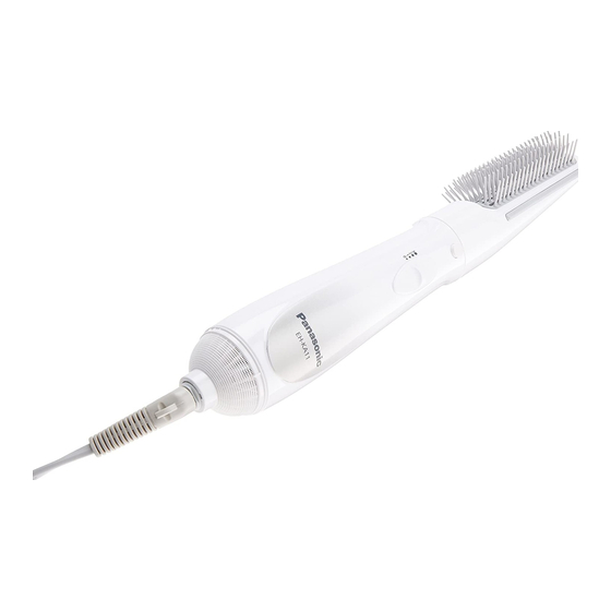
Hair Styler
EH-KA11
PAGE
Advertisement

Related Manuals for Panasonic EH-KA11


Summary of Contents for Panasonic EH-KA11
-
Page 1: Table Of Contents
5 Wiring Connection Diagram ---------------------------------- 6 6 Schematic Diagram ---------------------------------------------- 8 7 Exploded View and Replacement Parts List ------------ 9 © Panasonic Electric Works (Thailand) Co., Ltd. 2009. All rights reserved. Unauthorized copying and distribution is a violation of law. -
Page 2: Warning
1 Warning Caution: • Pb free solder has a higher melting point that standard solder; Typicall the melting point is 50 - 70°F (30 - 40°C) higher. Please use a soldering iron with temperature control and adjust it to 750 ± 20°F (400 ± 10°C). In case of using high temperature solder- ing iron, please be careful not to heat too long. -
Page 3: Troubleshooting Guide
3 Troubleshooting Guide (Refer to SCHEMATIC DIAGRAM and WIRING CONNECTION DIAGRAM.) -
Page 4: Disassembly And Assembly Instructions
4 Disassembly and Assembly Instructions 4.1. Disassembly Instructions 1. Remove the two Torx screws from the escutcheon, then remove the escutcheon, the filter and the fixing ring. 2. Separate the housing A and B by unfastening the hook. - Page 5 4.2. Caution In Assembly Refer to WIRING DIAGRAM to solder the wires. 1. Attach the lead wires (red for main switch and yellow for 3. Install the push button with coil spring and the arm switch heater) to the rectifier block from bottom. Then install rec- plate with switch plate on the housing B.
-
Page 6: Wiring Connection Diagram
5 Wiring Connection Diagram 5.1. Wiring Connection Diagram for 110V... - Page 7 5.2. Wiring Connection Diagram for 220-240V...
-
Page 8: Schematic Diagram
6 Schematic Diagram... -
Page 9: Exploded View And Replacement Parts List
7 Exploded View and Replacement Parts List Model No. : EH-KA11 Exploded View... - Page 10 Model No. : EH-KA11 Parts List Ref. Safety Part No. Part Name & Description Q'ty Remarks EHKA11HSW1W HOUSING AB 1 (FOR TAIWAN) EHKA11HSW2W HOUSING AB EHKA11HSW7W HOUSING AB 1 (FOR KOREA) EHKA11FTWSW FILTER 1 (FOR TAIWAN, VIETNAM, INDIA, IRAN) EHKA11FTWBW...