Lennox HARMONY III Installation, Setup And User Manual
Zoning system
Hide thumbs
Also See for HARMONY III:
- Installation instructions manual (60 pages) ,
- Manual (13 pages) ,
- Homeowner's manual (8 pages)

Related Manuals for Lennox HARMONY III


Summary of Contents for Lennox HARMONY III
- Page 1 HARMONY III™ zoning system (X9953) 507936-01 6/2021 Supersedes 7/2019 Installation, Setup and User Guide 2021 Lennox Industries Inc. © Dallas, Texas, USA...
-
Page 2: Table Of Contents
Table of Contents 1.10.9.1. Gas Furnace and Air Conditioning ............13 1.10.9.2. Heat Pump with Electric Backup Heat ..........13 1. General ..................4 1.10.9.3. Heat Pump - Dual Fuel heating, 1-stage or 2 Stage Heat Pump and Gas Furnace ..................13 1.1. - Page 3 5.2. Dual Fuel System Start-Up Defrost Temperating Sensor Placement and 3.3.1. Operation ......................27 Checkout ......................49 3.3.2. Integrated Furnace Control W2 terminal to Harmony III zoning system Control ......................... 28 5.2.1. Start-Up the System (All Models) ................ 49 3.3.3. Installation Setup Worksheets ................28 5.2.2.
-
Page 4: General
Zoning Accessory Kit (39W67) (required if Humiditrol EDA, above, is ® ® used) NOTE: Due to Lennox’ ongoing commitment to quality, features and options are eneral subject to change without notice and without incurring liability. Improper installation, adjustment, alteration, service or maintenance can cause 1.1. -
Page 5: Residential Zone Control System - Overview Of Field Wiring
• Remote Vacation Switch (optional; ordered separately) 1.5. Residential Zone Control System - Overview of Field 1.6.1. Zone Control System Wiring The Harmony III zoning system monitors electrical signals and directs control signals between thermostats, dampers, and HVAC equipment. ZONE 1 ZONE 2 THERMOSTAT (ZONE 1 OR CENTRAL CONTROL THERMOSTAT... -
Page 6: Discharge Air Sensor (Das)
1.6.6. Remote Vacation Switch • Non-power robbing The Harmony III zoning system control panel includes connections for an optional • Auto-changeover or non auto-changeover remote vacation switch (see “Figure 2. Harmony III Zoning System Zone Control • Lennox recommends that zone 1 thermostat (central [vacation] mode controller) Panel”... -
Page 7: Installation Planning And Selecting Heating And Cooling Equipment
3 options referenced in “1.7.3. Selecting/Installing CAUTION Indoor and Outdoor Units” as only those will work with the Harmony III zoning system; other types of units will not allow the Harmony III zoning system to This device is manufactured using unpainted and pre-painted metal. Sharp proportion the amount of air going to each zone. -
Page 8: Zone Control Panel
Refer to “Table zone control system power-up must occur at the same time or before the furnace 8. Lennox AC or Heat Pump Units” on page 7 which shows an example of an or air handler unit is powered up. -
Page 9: Zone Control Panel Jumpers
4 shows how the dampers may be linked to distribute some of the air from a small zone into another zone. HEATING STAGING JUMPERS ZONE 1 COOLING STAGING Note: Zone JUMPERS PIAB DAMPER Dampers are JUMPERS Power-Close CONTINUOUS AIR type. REDUCTION JUMPERS RELAY Zone 1 (smallest zone) -
Page 10: Upgrading From Harmony Ii Zoning System
10. Air Jumper Positions Conversion Chart” to maintain equivalent air 1.10.5. Determining PIAB Jumper Settings settings when setting up the Harmony III zoning system. NOTE: Use “6.3.2. PIAB Calculation Worksheet” on page 65 (also see example Table 10. Air Jumper Positions Conversion Chart below) to help calculate the zone control system PIAB settings. -
Page 11: Continuous Air Reduction Jumpers
The selections are 75%, 50%, 25% and 0%. At the factory, the jumper is set on airflow (CFM) requested by the Harmony III zoning system. 0%. Set the jumper to the position equal to the amount of continuous air reduction desired. -
Page 12: Cooling Staging Temperature Jumper
105F 2ND STAGE 1ST STAGE 2ND STAGE TIME When the zone control system is applied to a heat pump with electric heat, the electric heat will be staged ON to maintain the discharge air temperature set by the heating staging jumper position. Gas furnace with 160°F upper limit (range: 100 - 130; recommended: 120). The maximum discharge air temperature at which the furnace may run is fixed at 160°F. -
Page 13: Gas Furnace And Air Conditioning
1.10.9. System Configuration/E-Heat Stages) When using a heat pump with electric backup heat, insert an E-HEAT jumper to select the total number of available electric heat stages. The diagram above shows The SYSTEM configuration jumpers must be inserted to select the type of cooling a single heat-strip configuration. and heating system that has been installed and the E-HEAT Stages jumper defines if the system is dual fuel or defines the number of electric heating stages used. 1.10.9.3. Heat Pump - Dual Fuel heating, 1-stage or 2 Stage Heat Pump and Gas Furnace 1.10.9.1. -
Page 14: 1.11.2. Discharge Air Sensor (Das) Probe
(1-4) plus relays (K1-K4) not to exceed class II wiring limit of 75 VA. Combined load of zone dampers and zone relays not to exceed 60 VA. Use Lennox Catalog number 56L68 for Zone Relays 1 through 4. -
Page 15: Thermostat
• Use a 230VAC primary transformer with air handlers (CBX25UHV, CBX32MV, CBA38MV and CBX40UHV) The common C terminal of the Harmony III zoning system zone control panel • Use a 115VAC transformer with furnaces (SLP98, SL280V,EL296V and MUST be connected to the common terminal of the integrated control, or if using SL297NV) and with CBWMV. -
Page 16: Minimum Cfm In Variable Speed Furnace And Air Handlers
SLP98DF090XV48C** duty cycle corresponds to the maximum CFM. SLP98DF090XV60C** ** Listed values in the table correspond to 0% duty cycle of the Harmony III zoning SL280DF090V60C SLP98DF110XV60C** system control signal. Since the Harmony III zoning system puts 3% at minimum, SLP98UH070XV36B** actual value may be 10-30 CFM higher. -
Page 17: 1.14. System Flow Diagrams
1.14. System Flow Diagrams HEATING DEMAND RECEIVED COOLING DEMAND RECEIVED 5 minutes since completion of last heating demand 5 minutes since completion of last cooling Order of Staging: demand HP stg 1 (Y1) Energize (Y1/Y2) HP stg 2 (Y2) Energize heat strip compressor heat Elec strip stg 1 (W1) stage (W1/W2) and... -
Page 18: Heat Pump
2.1.4. Tee (High Pressure Switch; Heat Pumps only) Follow all equipment installation instructions provided with each unit. A tee (Lennox #87071) is needed to install the pressure switch along with a valve core (Schrader) for checking pressure in the vapor line during heat pump heating 2.1.2. -
Page 19: Defrost Tempering Kit
2.1.6. Defrost Tempering Kit A defrost tempering kit (67M41) may be implemented in a dual-fuel (Option 3) system. This kit consists of a thermostat probe/switch which is installed between the furnace and the evaporator coil to turn the furnace on (at 80°F) and off (at 90°F) during a defrost cycle. This tempers the discharge air and protects the compressor from high refrigeration pressures during defrost. The following figure show the defrost temperating kit components and see “Figure 4. -
Page 20: Variable Speed Motor (Vsm) Air Handler And Heat Pump - Option
VARIABLE SPEED AIR HANDLER NOTE: Select number of HP stages by placing jumper in appropriate position (2-Stage HP illustrated) System Configuration & E-Heat jumper settings Figure 20. Option 2 - Typical Lennox Heat Pump and Lennox Variable-Speed Air Handler (Troubleshooting) -
Page 21: Heat Pump System Start-Up And Checkout
2.3. Heat Pump System Start-Up and Checkout IMPORTANT The zone control system power-up must occur at the same time or before the furnace or air handler unit is powered up. 2.3.1. Powering the System (All Systems) 1. Adjust all thermostat settings so that no demand will occur. 2. -
Page 22: Typical Heat Pump Heating Checkout (Multiple Zone)
2.3.2.2. Typical Heat Pump Heating Checkout (Multiple Zone) 1. Apply heating demand to all thermostats. • All zone thermostat W LEDs on (heat demands). Prerequisites: All zone thermostats set to heat. • Output Heat LED Y1 on (compressor). • Heating and Fan LEDs on. •... -
Page 23: Typical Heat Pump Heating Checkout (Central Mode)
2.3.2.3. Typical Heat Pump Heating Checkout (Central Mode) 1. Set zone 1 thermostat for a heat demand; check: • Zone 1 thermostat W LED on (heating demand). Prerequisites: • Output Heat Y1 LED on (compressor on). • Central mode switch on •... -
Page 24: Heat Pump System Start-Up And Checkout
W1 energized during defrost? ing? Heating? Defrost? Emer. Heating? ately during defrost? sponse to demand? mand changes? If no, does DS output vary from 0 to 25VDC? Figure 21. Option 2 - Typical Lennox Heat Pump and Lennox Variable-Speed Air Handler (Troubleshooting) -
Page 25: Heat Pump Heating Operation
De-energize demand stages 1 and 2 and W1 & W2 satisfied blower fan @furnace Heating Heating demand Harmony III control demand satisfied de-energizes all satisfied compressor stages - uses auxiliary heat to complete existing heat demand De-energize all compressor stages... -
Page 26: Gas Furnace
COOL STAGES BY PLACING JUMPER IN IMPORTANT! APPROPRIATE POSITION. trical adjustments (jumpers and wiring changes) have been (2-STG CLG SHOWN) Figure 22. Harmony III zoning system Option 1 - Typical Lennox Variable-Speed Gas Furnace and 1- or 2-Stage Air Conditioner... -
Page 27: Furnace Variable Speed Motor Electrical Adjustments
The dehumidification on-board clippable link W914 Dehum - Harmony (R to DS) on the integrated furnace control must be cut for operation with the Harmony III zoning • The Harmony III zoning system control’s pulse width modulated (PWM) output system control. Once the link is cut, the presence of the Harmony III™ zoning signal is connected to the DS terminal on the furnace control. -
Page 28: Integrated Furnace Control W2 Terminal To Harmony Iii Zoning System Control
√ Cut on-board link W914 DEHUM OR HARMONY (R to DS) on furnace IFC control (if not cut, fuse will blow in Harmony III zoning system control board) Since the furnace automatically adjusts firing rate to match CFM to achieve a target √ W2 connection from Harmony III zoning system to SLP98 is optional – see Harmony III zoning temperature rise, connection of Harmony III zoning system control to W2 terminal system / furnace installation instructions for details on the integrated control is not required. √ DIP switch settings (ON or OFF): With W2 connected, lower firing rates can be used for W1 demand usually resulting DIP switches 6 and 7 –... -
Page 29: Sl280V, Sl280Nv, El296V And Sl297Nv - Cooling/Heating (Non-Heat Pump)
DIP Switch ON or OFF Condition 9 System Configuration DIP switch 1 – leave at factory setting – ignored by Harmony III Circle one: HP GAS Set to GAS jumpers zoning system Set to match condenser, 1 or DIP switch 2 –... -
Page 30: Zone Control Operation In A Gas Furnace System
√ Indoor Unit Wiring Completed: 3.3.4.2. Balance Point Setting DS” on Harmony III to “DS” on indoor unit connected (Dual Fuel Systems) Balance Point Sensor (kit 10Z23) communicates with the ”C” on indoor unit connected to Harmony III transformer “C”, zone control panel whether or not to force the Gas Furnace to satisfy heating No connection to “Y1”... -
Page 31: Zone Mode
3.3.4.5. Cooling Operation DIP switches 9 and 10 determines cooling blower ramping profile and When the Harmony III™ zoning system receives a thermostat cooling call, the is ignored by Harmony III zoning system following events occur: DIP switches 11 and 12 determines heating blower speed and is •... - Page 32 Actual CFM: Field Wiring Checklist √ Indoor Unit Wiring Completed: DS on Harmony III to DS on indoor unit connected C on indoor unit connected to Harmony III transformer C No connection to Y1 or Y2 on indoor unit. √...
-
Page 33: Furnace System Start-Up And Checkout
3.4. Furnace System Start-Up and Checkout IMPORTANT The zone control system power-up must occur at the same time or before the furnace or air handler unit is powered up. 3.4.1. Start-Up the System (All Models) 1. Adjust all thermostat settings so that no demand will occur. 2. -
Page 34: Typical Gas Heating Checkout (Multiple Zone)
3.4.2.2. Typical Gas Heating Checkout (Multiple Zone) 1. Apply heating demand to all thermostats. • All zone thermostat W LEDs on (heat demands) Prerequisites: All zone thermostats set to heat. • LEDs dampers 1 - 4 off (all dampers open) •... -
Page 35: Typical Gas Heating Checkout (Central Mode)
3.4.2.3. Typical Gas Heating Checkout (Central Mode) 1. Set zone 1 thermostat for a heat demand; check: • Zone 1 thermostat W LED on (heating demand). Prerequisites: • Output Heat Y1 LED on (furnace on). • Central mode switch on •... -
Page 36: Zoning System With Gas Furnace Troubleshooting - Option 1
3.5. Zoning System with Gas Furnace Troubleshooting - Option 1 3.5.1. Troubleshooting Diagrams Are thermostats wired correctly? Line Voltage to transformer? Does zone control system respond appropriately to demand? 24VAC from transformer to zone control panel? Are all wire connections good? Are all wire connections correct? Heat/cool thermostat used? (Must not use heat pump thermostat.) Does electronic thermostat have relay switching output? If not, isolation relays may need to be used. - Page 37 Is it operating properly? cooling? System Jumper Settings manual CONNECT HARMONY III W2 DIRECTLY TO (NOTE: Zone 1 may have a second gized in response to demand? jumper on 140F DAS pins) THE HIGH STAGE TERMINAL ON GAS VALVE...
-
Page 38: Gas Heating Operation
3.5.2. Gas Heating Operation 3.5.3. Discharge Air Upper Limit and Differential Temperatures HEATING DEMAND Furnace RECEIVED energized REFER TO DISCHARGE AIR 3-Minutes UPPER LIMIT DIAGRAM since completion (Page 38) FOR UPPER LIMIT Monitor of last heating AND DIFFERENTIAL DETAILS. demand discharge air temperature Energize W2... -
Page 39: Air Handlers
For any option or variation, connect thermostat wire between “C” Figure 26. Cooling Only on terminal strip(s) of controlled equipment and zone control Figure 27. Hot Water Coil and Current Lennox Air Handlers... -
Page 40: Electrical Adjustments
4.2.2. Non-Communicating Indoor Control Condensing Unit These air handler blower motors are controlled by the BDC3 drive control; CFM System configuration jumpers: adjustment Is by jumper setting selection. 1COOL or 2COOL. Locate the BDC3 board in the blower control box. Before connecting the zone control E-Heat stage jumper set on # panel to the BDC3 board, complete all of the applicable electrical adjustments as W1-Def... - Page 41 If this wire is not removed, the DS signal from the Harmony III zoning system control will not be able to vary the speed of the indoor blower motor.
-
Page 42: Installation Worksheets
√ Thermostat and Damper Wiring Completed HEAT HIGH Heating blower speed selection – Ignored by Harmony III zoning system √ Discharge Sensor wired to Harmony III zoning system DELAY Cooling blower ramping – Ignored by Harmony III zoning system BLOWER Continuous fan speed –... - Page 43 Setting affects both heating and cooling blower speeds (see blower tables ADJUST to determine setting) HEAT HIGH Heating blower speed selection – Ignored by Harmony III zoning system DELAY Cooling blower ramping – Ignored by Harmony III zoning system Panel Setup: 9 Heating staging jumper...
-
Page 44: 4.2.3.2. Heat Pump - Electric Strip Heat
Condition √ Indoor Unit Wiring Completed: This setting, along w/ ADJUST setting, determines maximum DS on Harmony III to DS on indoor unit connected COOL system CFM (See blower tables) C on indoor unit connected to Harmony III transformer C. - Page 45 9 On the CBX25UHV the blue wire that goes between plug # 2 of the circuit board and one side DS on Harmony III to DS on indoor unit connected of the contacts on the BR relay must be removed and connected to the G pigtail. Tape off end of C on indoor unit connected to Harmony III transformer C.
-
Page 46: Cooling Only Or Cooling With Hot Water Coil (Non-Heat Pump)
9 Cut on-board link R to DS “DEHUM or HARMONY” 9 For Hot Water Coil Only—Add K212 Relay and wire per Harmony III wiring detail. NOTE - NOTE: All of the above are recommended starting positions for DIP switches and Discharge air sensor must be located downstream of cooling coil and hot water coil. - Page 47 DELAY Harmony III zoning system √ Discharge Sensor wired to Harmony III zoning system and if a hot water coil is used, the sensor must be located down stream of the hot water coil. Panel Setup: 9 Heating staging jumper...
-
Page 48: Dual Fuel (Option 3)
BY PLACING JUMPER IN APPROPRIATE IMPORTANT! Connectivity is NOT COMPLETE until all POSITION. (2-STG HP SHOWN) electrical adjustments (jumpers and wiring changes) have Figure 32. Option 3 - Typical Lennox Heat Pump and Lennox Variable-Speed Gas Furnace (Dual Fuel) (Troubleshooting) -
Page 49: Dual Fuel System Start-Up Defrost Temperating Sensor Placement And Checkout
5.2. Dual Fuel System Start-Up Defrost Temperating Sensor Placement and Checkout 5.2.1. Start-Up the System (All Models) 1. Adjust all thermostat settings so that no demand will occur. 2. Apply power to the zone panel transformer and to the furnace and observe the following: all four diagnostic LEDs will light;... -
Page 50: Checkouts
5.2.3. Checkouts 5.2.3.1. Typical Dual Fuel Gas Heating (Single Zone) 1. Set zone 1 thermostat for a heat demand; check: Zone 1 thermostat W LED on (heating demand). • Prerequisites: • Damper LED 1 off (damper open). • Zone 1 thermostat set to Heat. •... -
Page 51: Typical Dual Fuel Gas Heating (Multiple Zone)
5.2.3.2. Typical Dual Fuel Gas Heating (Multiple Zone) 1. Set all zone thermostats for a heat demand; check: • All zone 1 thermostat W LED on (heating demand). Prerequisites: • Damper LED 1 - 4 off (all damper open). Zone 1 thermostat set to Heat. •... -
Page 52: Typical Dual Fuel Gas Heating (Central Mode)
5.2.3.3. Typical Dual Fuel Gas Heating (Central Mode) 1. Set zone 1 thermostat for a heat demand; check: • Zone 1 thermostat W LED on (heating demand). Prerequisites: • Output Heat W1 LED on (furnace on). • Central mode switch on. •... -
Page 53: Zoning System With Dual Fuel Troubleshooting - Option 3
Does indoor unit respond to outputs? Cooling? Heating? Defrost? Emer. Heating? Does blower speed change as zone demand changes? If no, does DS output vary from 0 to 25VDC? Figure 34. Option 3 - Typical Lennox Heat Pump and Lennox Variable-Speed Gas Furnace (Dual Fuel) (Troubleshooting... -
Page 54: Dual Fuel Operation (Below Balance Point)
5.3.2. Dual Fuel Operation (Below Balance Point) 5.3.3. Discharge Air Upper Limit and Differential Temperatures HEATING DEMAND Furnace energized RECEIVED Ambient See Above Balance Monitor temp. Below Point Sensor discharge air Balance Point setpoint flow diagram Sensor setpoint temperature Discharge air upper limit is 160ºF unless 140ºF DAS jumper installed discharge air at upper... -
Page 55: Dual Fuel Operation (Above Balance Point)
De-energize Heating Heating all heat pump demand demand satisfied satisfied and furnace Heating stages Harmony III control demand de-energizes all satisfied System compressor stages - uses in 3-hr backup pressor stages; start heat mode auxiliary heat to complete 5-minute delay... -
Page 56: Installation Setup Worksheets
DIP switches 7 and 8 determine blower “adjust” setting √ Indoor Unit Wiring Completed: for maximum system air volume DS on Harmony III to DS on indoor unit connected DIP switches 9 and 10 determines cooling blower ramping profile and is ignored by Harmony III zoning C on indoor unit connected to Harmony III transformer C system No connection to Y1 or Y2 on indoor unit. -
Page 57: 5.3.6.2. Dual Fuel - Slp98 Variable Capacity And Heat Pump
Total system CFM per Minimum CFM: with all zones calling: tables: DIP Switch ON or OFF Condition DIP switch 1 – leave at factory setting – ignored by Harmony III zoning 9 Zone 1 Name: Desired CFM: PIAB Setting: Actual CFM: system... -
Page 58: Dual Fuel - Variable Speed Sl280V, El296V, Sl297Nv And Heat Pump
Circle one: 0 25 50 75 Percentage airflow reduction Miscellaneous Items: for continuous fan operation 9 Install Pressure Switch in the outdoor unit per Harmony III installation instructions (27W13 for 9 Heating Air Reduction Circle one: 0 20 40 Percentage air flow reduction R410A or 27W12 for R22) -
Page 59: Troubleshooting
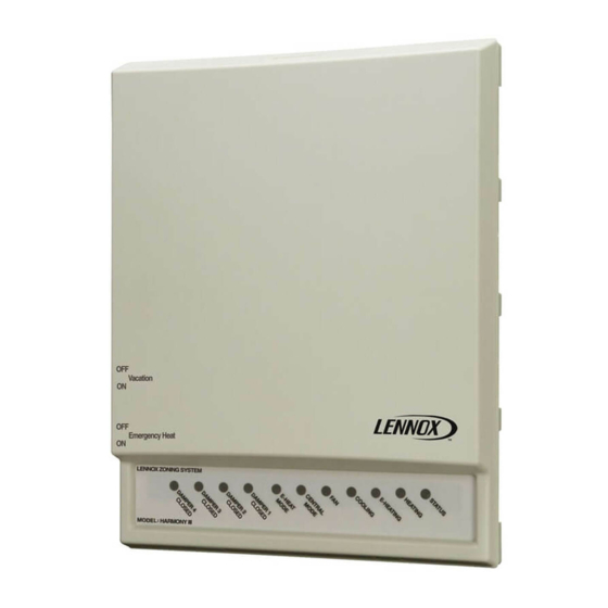
rOublesHOOtinG 6.1. Operation and Troubleshooting Indicators 6.1.1. Zone Control Panel LEDs The zone control system operation is indicated by light emitting diodes (LEDs) located on the zone control panel. In addition to operating condition, the LEDs provide valuable information system troubleshooting. The LEDs (shown in figure OUTDOOR THERMOSTAT / 30) are thermostat, diagnostic, and output status. -
Page 60: Fault Recall And Time Delay Override
6.1.2. Fault Recall and Time Delay Override Table 14. Time Delays When the Time Delay Override is pressed and held, the internal clock speeds up Delay Time Function by a factor of 60. This overrides the current time delay and permits the next event This timer is defined as the amount of time to occur. “Table 14. Time Delays” on page 60 identifies the time delays used by to hold the last zone calling open past the... -
Page 61: Blower Speed Checkout
Do not touch both probes with your fingers—doing so will produce a faulty reading. runs at a minimum fan speed, check and make sure C on the indoor unit is At 77°F, the resistance of the sensor will be 10K ohm; at lower probe temperatures, connected to C on the zone panel transformer connection. expect higher resistance; at warmer probe temperatures, expect lower resistance. NOTE: SLP98 furnace models are equipped with an LED on the integrated control which displays blower airflow in all modes of operation. -
Page 62: Diagnostic Led Error Codes
6.2. Diagnostic LED Error Codes The blower may run during a fail-safe condition after a heating demand. This is due to the operation of the integrated control inside the furnace. When the zone control system finds a problem (error condition), it will turn on If a shutdown condition occurs while there is a call for cooling, a five-minute timer one or more of the diagnostic LEDs on the zone control. -
Page 63: Air Delivered By Blower
Table 15. Diagnostics Codes Fail-safe (0-off;1-on) Code (System Diag Fault Indicated Remedy Shut LED1234 Down) Open pressure Displayed when the pressure switch opens and does not necessarily mean there is anything wrong. However, try increasing the air delivered to switch (heat 1001 the smallest zone. - Page 64 Table 18. Determine Total Continuous CFM delivered Table 16. Determine total PIAB and Total CFM Delivered Example values Jumpers Jumpers Cont. Air Heating Air Min. Max. Reduction Red. Cont. Air Heating Air Min. Max. Reduction Red. 2200 2200 Gray zones are calling. •...
-
Page 65: Piab Calculation Worksheet
6.3.2. PIAB Calculation Worksheet PIAB Calculation Worksheet PIAB = [(Required CFM - Minimum CFM) / (Maximum CFM - Minimum CFM)] * 100 Sample CFM Required Minimum Maximum Minimum Sample PIAB = ([___920 ] / [ 2000 x 100 Sample PIAB = ([ ] / [ 1550 x 100... -
Page 66: Airflow Data
All of the below are approximations and examples only. All equipment can differ output by load and system matching. All the attached is meant to show common examples for safe operation of Lennox equipment. CFM valves are not all exact available targets but will yield a close approximation to all applications. - Page 67 ml296uHV-56 Table 20. ML296 Model ML296UH045XV36B ML296UH070XV36B ML296UH090XV48C ML296UH110XV60C 519 CFM @50˚F TR 690 CFM @55˚F TR 849 CFM @60˚F TR 997 CFM @65˚F TR Minimum CFM For Zoning Output BTU 28,000 Output BTU 41,000 Output BTU 55,000 Output BTU 70,000 780 CFM @33˚F TR 900 CFM @42˚F TR 1,135 CFM @45˚F TR 1,375 CFM @47˚F TR Factory CFM Output BTU 28,000 Output BTU 41,000 Output BTU 55,000 Output BTU 70,000 1,296 CFM @30˚F TR...
- Page 68 Table 22. EL296DFV Model EL296DF045XV36B EL296DF070XV48B EL296DF090XV60C EL296DF110XV60C 518 CFM @50˚F TR 707 CFM @55˚F TR 864CFM @60˚F TR 997CFM @65˚F TR Minimum CFM Output BTU 28,000 Output BTU 42,000 Output BTU 56,000 Output BTU 70,000 745 CFM @35˚F TR 850 CFM @46˚F TR 1160CFM @45˚F TR 1220CFM @57˚F TR Factory CFM Output BTU 28,000 Output BTU 42,000 Output BTU 56,000 Output BTU 70,000 1,137 CFM @35˚F TR 1,693 CFM @35˚F TR...
- Page 69 Table 24. SL280UHNV Model SL280UH060NV36A SL280UH080NV48B SL280UH080NV60C SL280UH100NV60C 574 CFM @50˚F TR 759 CFM @50˚F TR 759 CFM @50˚F TR 963 CFM @50˚F TR Minimum CFM Output BTU 31,000 Output BTU 41,000 Output BTU 41,000 Output BTU 52,000 825 CFM @35˚F TR 1,060 CFM @36˚F TR 1,130 CFM @34˚F TR 1,425 CFM @34˚F TR Factory CFM Output BTU 31,000 Output BTU 41,000 Output BTU 41,000 Output BTU 52,000 1,482 CFM @30˚F TR 1,975 CFM @30˚F TR...
- Page 70 slP99uHV Table 27. SLP99UHV Starting at 70% of High Fire (Temperature rise based on primary limit and room at 70˚ and before tripping furnace primary limit) Model SLP99UH070XV36B SLP99UH090XV36C SLP99UH090XV48C SLP99UH090XV60C Primary Limit 145˚F 150˚F 140˚F 140˚F 553 CFM @75˚F TR 688 @80˚F TR 787 CFM @70˚F TR 805 CFM @70˚F TR Minimum CFM (Fail at CFM) Zoning Output BTU 44,800 Output BTU 59,500 Output BTU 59,500 Output BTU 60,900 1,185 CFM @50˚F TR 1,312 CFM @60˚F TR...
- Page 71 Table 28. SLP99DF Starting at 70% of High Fire (Temperature rise based on primary limit and room at 70˚and before tripping furnace primary limit) Model SLP99DF070XV36B SLP99DF090XV36C SLP99DF090XV48C SLP99DF090XV60C Primary Limit 145˚F 145˚F 140˚F 140˚F 553 CFM @75˚F TR 726 CFM @75˚F TR 787 CFM @70˚F TR 787 CFM @70˚F TR Minimum CFM (Fail at CFM) Zoning Output BTU 44,800 Output BTU 58,800 Output BTU 59,500 Output BTU 59,500 1,185 CFM @50˚F TR 1,296 CFM @60˚F TR...
- Page 72 inGle taGe OndensinG OOlinG Table 29. Single Stage Condensing In Cooling (At minimum blower CFM superheat must be at or above 5˚SH) Size 1.5 Tons 2 Tons 2.5 Tons 3 Tons Minimum CFM @180 CFM 270 CFM 360 CFM 450 CFM 540 CFM Per Ton Recommend CFM @300 CFM Per Ton 450 CFM 600 CFM 750 CFM...
- Page 73 inGle taGe eatinG Table 30. Single Stage Heat Pump In Heating (Maximum pressure approximately @ 525PSI) Size 1.5 Tons 2 Tons 2.5 Tons 3 Tons Minimum CFM @380 CFM 570 CFM 760 CFM 950 CFM 1,140 CFM Per Ton Recommend CFM @450 CFM Per Ton 675 CFM 900 CFM 1,125 CFM...
- Page 74 taGe irst taGe eatinG Table 32. Two Stage Heat Pump Unit In First Stage Heating (Maximum pressure approximately @525PSI) Size 2 Tons 3 Tons 4 Tons 5 Tons Unit In First Stage 1.34 Tons 2.01 Tons 2.68 Tons 3.35 Tons Minimum CFM @380 CFM 509 CFM 764 CFM 1,018 CFM 1,273 CFM Per Ton...
- Page 75 ariable OndensinG inimum eatinG Table 34. Variable Condensing Unit Minimum Heat Pump Heating CFM (Maximum pressure approximately @525PSI) Model EL18XPV-024 EL18XPV-036 EL18XPV-048 EL18XPV-060 System at Minimum Capacity .875 Tons .86 Tons 1.6 Tons 1.78 Tons Minimum CFM @380 CFM Per Ton 333 CFM 327 CFM 608 CFM...
- Page 76 cFm ecb38-P cba38mV lectric eatinG Table 36. Electric Heating CFM ECB38-P CBA38MV (@240VAC 3.413 BTU per Watt) Size by kW No. Of Stages Low Heating BTU Airflow to 30°Tr Max Heating BTU 13,652 421 CFM 13,652 17,065 527 CFM 17,065 20,478 632 CFM 20,478 13,652 421 CFM 27,304...
-
Page 77: User Guide
This will prevent problems associated with a NO HEAT condition (frozen pipes, etc.) The principle system component is the control center which acts as the “brains” of the Harmony III zoning system. It coordinates all of the operations of thermostats, motorized dampers, and HVAC equipment. 8.4. - Page 78 ® 8.7. How are Zones Determined? installed, ask for a copy of those kit’s installation and operation instructions. Your Lennox dealer has sectioned the rooms of your home or building into zones 8.12. Thermostat replacement using the following considerations: • Structural and Architectural Considerations - In multi-level houses using...
- Page 79 8.14. Homeowners Zone Information Record Table 37. Homeowners Zone Information Record Zone Number Record which rooms are zoned together and controlled by thermostat number. Lennox Dealer: Contact: Telephone Number: Installation Date...