Table of Contents
Advertisement
Quick Links
Installation Instructions
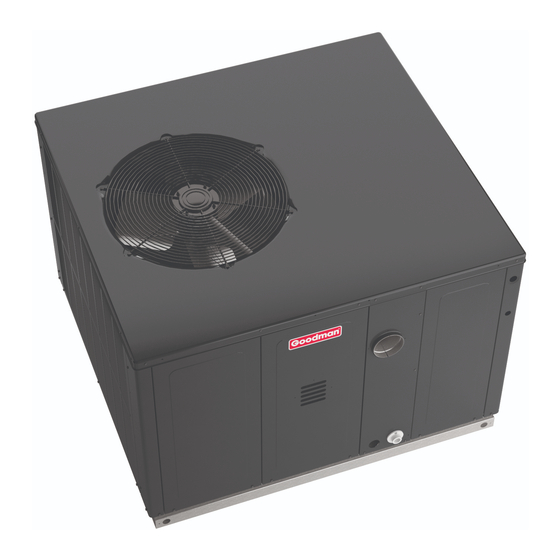
GPGM5 15.2 SEER2 "M" SERIES 2-4 TON
Single Package Gas-Electric Heating & Cooling Units
ATTENTION INSTALLING PERSONNEL
Prior to installation, thoroughly familiarize yourself with this
Installation Manual. Observe all safety warnings. During in-
stallation or repair, caution is to be observed.
It is your responsibility to install the product safely and to
educate the customer on its safe use.
RECOGNIZE THIS SYMBOL AS
A SAFETY PRECAUTION.
These installation instructions cover the outdoor installa-
tion of self contained package air conditioners and heating
units. See the Specification Sheets applicable to your
model for information regarding accessories.
IOG-3026
06/2022
"IMPORTANT - This product has been designed and manufactured to meet ENERGY STAR®
criteria for energy efficiency when matched with appropriate coil components. However,
proper refrigerant charge and proper air flow are critical to achieve rated capacity and
efficiency. Installation of this product should follow the manufacturer's refrigerant charging
and air flow instructions. Failure to confirm proper charge and air flow may reduce energy
efficiency and shorten equipment life."
Daikin Comfort Technologies Manufacturing, L.P.
19001 Kermier Rd., Waller, TX 77484
www.goodmanmfg.com
© 2022 Daikin Comfort Technologies Manufacturing, L.P.
Affix this manual and Users Information Manual
adjacent to the unit.
Only personnel that have been trained to install, adjust,
service or repair(hereinafter, "service") the equipment
specified in this manual should service the equipment. The
manufacturer will not be responsible for any injury or
property damage arising from improper service or service
procedures. If you service this unit, you assume responsi-
bility for any injury or property damage which may result.
In addition, in jurisdictions that require one or more
licenses to service the equipment specified in this manual,
only licensed personnel should service the equipment.
Improper installation, adjustment, servicing or repair of
the equipment specified in this manual, or attempting to
install, adjust, service or repair the equipment specified in
this manual without proper training may result in product
damage, property damage, personal injury or death.
*NOTE: Please contact your distributor or our website
for the applicable Specification Sheets referred to in this
manual.
This Forced Air Central Unit Design Complies With Re-
quirements Embodied In The American National Standard /
National Standard of Canada Shown Below.
ANSI Z21.47•CSA-2.3 Central Furnaces.
Do not bypass safety devices.
WARNING
WARNING
Advertisement
Table of Contents

Related Manuals for Daikin GPGM5


Summary of Contents for Daikin GPGM5
- Page 1 Installation Instructions GPGM5 15.2 SEER2 “M” SERIES 2-4 TON Single Package Gas-Electric Heating & Cooling Units Affix this manual and Users Information Manual adjacent to the unit. WARNING Only personnel that have been trained to install, adjust, service or repair(hereinafter, “service”) the equipment specified in this manual should service the equipment.
-
Page 2: Table Of Contents
When reporting shortages or damages, or ordering repair parts, give the complete unit model and serial numbers as HOMEOWNER SUPPORT stamped on the unit’s nameplate. Daikin Comfort Technologies Manufacturing, L.P. 19001 KERMIER ROAD WALLER, TEXAS 77484 (877) 254-4729... -
Page 3: Safety Instructions
SAFETY INSTRUCTIONS WARNING To The Installer Heating unit should not be utilized without reasonable, Before installing this unit, please read this manual to routine, inspection, maintenance and supervision. If the familiarize yourself on the specific items which must be building in which any such device is located will be vacant, adhered to, including maximum external static pressure to care should be taken that such device is routinely inspected, unit, air temperature rise, minimum or maximum CFM and... - Page 4 WARNING AVERTISSEMENT CARBON MONOXIDE POISONING HAZARD RISQUE D’INTOXICATION AU MONOXYDE DE CARBONE Failure to follow the steps outlined below for each Si les étapes décrites ci-dessous ne sont pas suivies pour appliance connected to the venting system being placed chacun des appareils raccordés au système de ventilation into operation could result in carbon monoxide poisoning au moment de sa mise en marche, cela peut entraîner une or death.
-
Page 5: General Information
RISQUE D'EMPOISONNEMENT AU MONOXYDE DE CARBONE Advertencia especial para la instalación de calentadores ó manejadoras de aire en áreas cerradas como estacionamientos ó cuartos de servicio. Cette ventilation est nécessaire pour éviter le danger d'intoxication Las emisiones de monóxido de carbono pueden circular a través au CO pouvant survenir si un appareil produisant du monoxyde del aparato cuando se opera en cualquier modo. -
Page 6: Unit Location
UNIT LOCATION • The top of the unit should be completely unobstructed. If units are to be located under an overhang, there should be a minimum of 48” clearance and provisions IMPORTANT NOTE: Remove wood shipping rails pri- made to deflect the warm discharge air out from the or to installation of the unit. -
Page 7: Roof Curb Installations Only
WARNING Model Roof Curb To avoid property damage, personal injury or death when GPGM5(24-48)***M41** D14CRBPGCHMA either using propane gas alone or at higher altitudes, obtain and install the proper conversion kit(s). Failure to do so can result in unsatisfactory operation and/or equipment damage. -
Page 8: High Altitude Derate (U.s. Installations Only)
The rating plate is stamped with the model number, type of Piping gas and gas input rating. Make sure the unit is equipped to IMPORTANT NOTE: To avoid possible unsatisfactory operate on the type of gas available. Conversion to LP gas operation or equipment damage due to under firing of equipment, do not undersize the natural/propane is permitted with the use of a factory authorized conversion... -
Page 9: Gas Piping Checks
IMPORTANT NOTE: For Natural gas to LP gas Natural Gas Capacity of Pipe conversion, Conversion Kit “LPM-08” must be used. in Cubic Feet of Gas Per Hour (CFH) Consult your dealer for appropriate conversion Nominal Black Pipe Size (inches) Length of kit(s). -
Page 10: Electrical Wiring
WARNING 5 to 15 PSIG First Stage (20 PSIG Max.) Regulator Continuous 11" W.C. To avoid property damage, personal injury or death due to fire or explosion caused by a propane gas leak, install a gas detecting warning device. If the propane gas unit is installed 200 PSIG Second Stage in an excavated area or a confined space, a confined space, a... -
Page 11: Unit Voltage
To use a single stage thermostat, move jumper located 5 MINUTE DELAY to the left of the terminal strip labeled “Stage Delay” from PERIOD WITH NONE to “5” or “10” minutes. This selection will cause the JUMPER IN THIS control to run on low stage for the selected time (5 or 10 min- POSITION utes) then shift to HIGH STAGE. -
Page 12: Circulating Air And Filters
The induced draft blower on some models is equipped Down Discharge Applications with a low speed 240V lead (blue) and a low speed 208V Cut insulation around bottom openings and remove panels lead (black). If the unit is to operate on 208V, connect the from the bottom of the unit, saving the screws holding the induced draft blower low speed 208V lead (black) in place panels in place. -
Page 13: Venting
CONDENSATE DRAIN Filters installed external to the unit should be sized in accordance with their manufacturer recommendations. A throwaway filter must be sized for a maximum face velocity Condensate Drain Connection of 300 feet per minute. A 3/4” NPT drain connection is supplied for condensate piping. -
Page 14: Cooling
NOTE: After the HEAT FAN OFF delay time has elapsed, the blower will de-energize. This allows WARNING any additional heat in the heat exchanger to be transferred to the conditioned space. To avoid property damage, personal injury or death due to fire or explosion, a qualified servicer must investigate the reason for the rollout protection device to open BEFORE Cooling... - Page 15 Do not force. 2. Connect a water manometer or adequate gauge to the 7. Wait five minutes to clear out any gas. inlet pressure tap of the gas valve (or hose barb fitting 8. Smell for gas, including near the ground. This is im- on predrilled cap).
-
Page 16: Gas Btu Input Check (Natural Only)
Manifold Pressure Check Manifold Gas Pressure 1. Turn OFF gas to furnace at the manual gas shutoff valve external to the furnace. Range Nominal 2. Turn off all electrical power to the system. Low Sta ge 1.7 - 2.3" w.c. 2.0"... -
Page 17: Total External Static Testing
The total external static pressure must be checked on this NOTE: FAN ONLY energizes at LOW HEAT speed. The unit to determine if the airflow is proper. GPGM5 models are equipped with EEM motors. EEM motors are constant torque motors with very low Total External Static Testing power consumption. -
Page 18: Cooling Startup
Limit Check Checking Subcooling Check limit control operation after 15 minutes of operation NOTE: Units with a TXV should be charged to Sub- by blocking the return air grille(s). cooling only. 1. After several minutes the main burners must go OFF. Blower will continue to run. -
Page 19: Troubleshooting
(Units with Expansion Valve (TXV)) Remove the control box access panel and note the number Single Stage Cooling Application: Refer to the Design Su- of diagnostic LED flashes. Refer to Diagnostic Indicator perheat & Subcooling table. Chart for an interpretation of the signal and to this section for an explanation. -
Page 20: Pressure Switch Stuck Open
NOTE: If the primary limit opens five (5) times with- • Auxiliary/Secondary Limit A dirty filter, excessive duct static, insufficient air flow, a in the same call for heat, the ignition control will faulty limit, or a failed circulator blower can cause this lock out for one (1) hour with the air circulating blower energized at high heat speed. -
Page 21: Maintenance
MAINTENANCE Flame Sensor WARNING HIGH VOLTAGE! Disconnect all power before servicing or installing this unit. Multiple power sources may be present. Failure to do so may cause property damage, personal injury or death. Have the gas heating section of the unit checked at least once a year before the heating season begins, to be sure that the combustion air inlet and flue outlet hoods are not blocked by debris, which would prevent adequate combus-... -
Page 22: Cleaning Burners
If a strong wind is blowing, it may alter the airflow pattern Burner within the unit enough that an inspection of the burner flames is not possible. Burner Bracket Check the Burner Flames for: Manifold 1. Stable, soft and blue. 2. -
Page 23: Appendix
APPENDIX Ignition Control Diagnostic Indicator Chart Red Light Signal Refer to Abnormal Heating or Cooling Operation Sections of this Manual Internal Control Failure 1 Flash External Lockout 2 Flashes Pressure Switch Stuck Open 3 Flashes Pressure Switch Stuck Closed 4 Flashes Thermal Protection Device Open 5 Flashes Flame Detected with Gas Valve Closed... -
Page 24: Unit Dimensions
UNIT DIMENSIONS Unit Dimensions (Inches) Model Height Chassis Size GPGM524***41** 34 1/2 Medium GPGM530***41** 34 1/2 Medium GPGM536***41** 42 1/2 Large GPGM542***41** 42 1/2 Large GPGM548***41** 42 1/2 Large POWER WIRE ENTRANCE 1.375 4.125 2.125 RETURN 4.75 CONDENSATE DRAIN CONNECTION SUPPLY 3/4"... -
Page 25: Wiring Diagram
GPGM5[24/30/36/42/48]**41 WIRING DIAGRAM HIGH VOLTAGE! ISCONNECT POWER BEFORE SERVICING ULTIPLE POWER SOURCES MAY BE PRESENT AILURE TO DO SO MAY CAUSE PROPERTY DAMAGE, PERSONAL INJURY OR DEATH PLY VOLTAGE 208- 230/1/6 COMP SEE NOTE 4 SEE NOTE 3 SEE NOTE 2... -
Page 26: Blower Performance
BLOWER PERFORMANCE DATA GPGM52406041 - Rise Range: 25° - 55° T1 LOW STAGE HEATING T2 HIGH STAGE HEATING T3 LOW STAGE T4 HIGH STAGE T5 COOLING SPEED E.S.P. SPEED SPEED COOLING SPEED COOLING SPEED WATTS WATTS RISE WATTS RISE WATTS WATTS 1080 1021... - Page 27 PACKAGE UNITS - DUAL FUEL & GAS HOMEOWNER’S ROUTINE MAINTENANCE RECOMMENDATIONS We strongly recommend a bi-annual maintenance checkup be performed by a qualified service agency before the heating and cooling seasons begin. Replace or Clean Filter literature bag with the unit) to clean the coils. The cleaners listed are the only agents deemed safe and approved for use to clean WARNING round tube aluminum coils.
-
Page 28: Start-Up Checklist
START-UP CHECKLIST Residential Package - (Indoor Section) Model Number Serial Number ELECTRICAL Line Voltage (Measure L1 and L2 Voltage) L1 - L2 Secondary Voltage (Measure Transformer Output Voltage) R - C Blower Amps Heat Strip 1 - Amps Heat Strip 2 - Amps BLOWER EXTERNAL STATIC PRESSURE Return Air Static Pressure IN. - Page 29 THIS PAGE LEFT INTENTIONALLY BLANK...
- Page 30 THIS PAGE LEFT INTENTIONALLY BLANK...
- Page 31 THIS PAGE LEFT INTENTIONALLY BLANK...
- Page 32 We use quality materials and components. Finally, every unit is run tested before it leaves the factory. That’s why we know. . .There’s No Better Quality. Daikin Comfort Technologies Manufacturing, L.P. 19001 Kermier Rd., Waller, TX 77484 www.goodmanmfg.com © 2022 Daikin Comfort Technologies Manufacturing, L.P.