Advertisement
Quick Links
Advertisement

Related Manuals for Timken ROLLON SC 100

Summary of Contents for Timken ROLLON SC 100
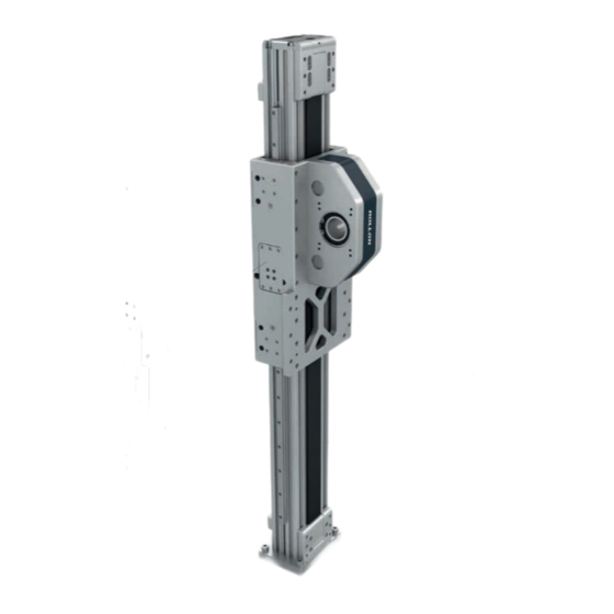
- Page 1 Smart System Actuator Line Plus system Use and maintenance...
-
Page 3: Table Of Contents
Content Use and maintenance Lubrication, Drive belt replacement UM-2 Replacement of the ball re-circulation sliding blocks UM-6 Assembly of clamp/brake unit (only for SC130 and SC160) UM-7 Proximity switch adjustment, Warnings UM-8 Gearbox side replacement UM-9 Gearbox assembly UM-9 Components UM-10 Warnings and legal notes UM-11... -
Page 4: Use And Maintenance
Use and maintenance Linear units with linear ball guides This system guarantees a long interval between maintenan- SC Linear units are equipped with self lubricating linear ball ces: every 5000 km or 1 year of use, based on the value guides. - Page 5 Smart System 3) Untight the 4 screws and remove the upper plate at the end of the aluminum profile (see Fig.4). Fig. 4 4) Remove the screws of the belt clamp plate and separate it from the actuator (see Fig. 5, Fig. 6 and Fig. 7). Fig.
- Page 6 6) Remove all the screws of the lower belt clamp plate and sepa- rate it from the actuator (see Fig. 10, Fig. 11 and Fig. 12). Fig. 12 Fig. 10 Fig. 11 7) Untight the screws which fix the driving head plate and remove the head from the actuator.
- Page 7 Smart System 8) Insert the new belt inside the driving head taking care about the orientation of the teeth which must engage with the dri- ving pulley (see Fig. 15). 9) Re-assembly the driving head plate (see Fig. 16). Fig. 15 Fig.
-
Page 8: Replacement Of The Ball Re-Circulation Sliding Blocks
Replacement of the ball re-circulation sliding blocks 1) Remove the cover plate on top or lower side of the carriage depending where the sliding block has to be replaced. Unscrew the two screws (see Fig.19). 2) Loosen and remove the sliding block screws. 3) Slide out the sliding block. -
Page 9: Assembly Of Clamp/Brake Unit (Only For Sc130 And Sc160
Smart System Assembly of clamp/brake unit (only for SC130 and SC160) 1) Remove the screws and the plates on both sides of the car- riage (see Fig. 22). 2) Assembly the clamp/brake on the plate taking care about the right orientation as shown in the picture. Before tightening completely the screws push the clamp/brake against the reference sides on the plate. -
Page 10: Proximity Switch Adjustment, Warnings
Proximity switch adjustment 1) Identifiy the position along the actuator where the limit switch must work, there the sensor dog must be fixed. 2) Insert the fixing nuts in the profile slot accessing through the upper plate. Repeat the operation also for the sensor dog to be installed in the lower side of the profile (Fig.26). -
Page 11: Gearbox Assembly
Smart System Gearbox assembly Place the axis as shown in the figure with the gear assem- Tightening sequence of the shrink disc screws until a tor- ■ ■ bly component facing upwards. que value is obtained as in Tab. 3: Assemble the flange (1) on the gear and tighten the screws Tighten all the screws to 50% of the value of the tighte- ■... -
Page 12: Components
RIGHT POSITION OF THE ELEMENTS IT IS FORBIDDEN IT IS NOT TO ASSEMBLE THE RECOMMENDED RINGS WITH THE TO ASSEMBLE THE THREADS ALIGNED RINGS WITH THE CUTS ALIGNED In the image below are reported the correct angle positions of the components that build the shrink ring to use only in the case it was dismounted completely. -
Page 13: Warnings And Legal Notes
Smart System Warnings and legal notes Before incorporating the partly completed machinery, The manufacturer cannot be considered responsible we recommend consulting this chapter carefully, in for any consequences derived from improper use or addition to the assembly manual supplied with the any use other than the purpose the axis or system individual modules. - Page 14 Residual risks Mechanical risks due to the presence of moving elements (X, Y Risk of the Z axis dropping during maintenance operations in ■ ■ axes). the case of a drop in the electrical power supply voltage. Risk of fire resulting from the flammability of the belts used on Crushing hazard near moving parts with divergent and ■...
- Page 15 Smart System Safety warnings for handling and transport The manufacturer has paid the utmost attention to packaging to Mark and delimit the established location to prevent unauthori- ■ ■ minimize risks related to shipping, handling and transport. zed personnel from accessing the installation area. Transport can be facilitated by shipping certain components The installation site must have adequate environmental condi- ■...
- Page 16 Warnings and legal notes Transport Transport, also based on the final destination, can be done with ■ different vehicles. Perform transport with suitable devices that have adequate ■ loading capacity. Ensure that the machine and its components are adequately ■ anchored to the vehicle.
- Page 17 Smart System UM-15...
- Page 18 EUROPE ROLLON S.p.A. - ITALY (Headquarters) ROLLON GMBH - GERMANY Via Trieste 26 Bonner Straße 317-319 20871 Vimercate (MB) 40589 Düsseldorf Phone +39 039 62591 Phone +49 (0)211957470 infocom@rollon.com info@rollon.de www.rollon.com www.rollon.de ROLLON S.A.R.L. - FRANCE Les Jardins d’Eole 2 allée des Séquoias 69760 Limonest Phone +33 (0)474719330 infocom@rollon.fr...