
Related Manuals for Busch-Welcome H8131 P-03 Series

Summary of Contents for Busch-Welcome H8131 P-03 Series
- Page 1 2TMD042200D0021 │ 22.06.2022 Product manual ® Busch-Welcome H8131.P.-.-03 Mini video outdoor station H8136.P.-.-03 Mini video outdoor station...
-
Page 2: Table Of Contents
Table of contents Tab le of c ont e nts Notes on the instruction manual ......................4 Safety ..............................4 Intended use ............................4 Environment ............................5 Busch-Jaeger devices ........................ 5 Product description ..........................6 Device type ..........................6 Control elements........................7 Terminal description ........................ - Page 3 Table of contents Cyber security ............................ 45 Disclaimer ..........................45 Performance and service ......................45 Deployment guideline....................... 46 Upgrading..........................46 Backup/Restore ........................46 Malware prevention solution ..................... 46 Notice ..............................47 │3 Product manual 2TMD042200D0021...
-
Page 4: Notes On The Instruction Manual
Permit work on the 100-240 V supply system to be performed only by specialist staff! Intended use ® As part of the Busch-Welcome IP system, this device can only be used with accessories from that system. │4 Product manual 2TMD042200D0021... -
Page 5: Environment
Environment Environment Consider the protection of the environment! Used electric and electronic devices must not be disposed of with household waste. – The device contains valuable raw materials that can be recycled. Therefore, dispose of the device at the appropriate collecting facility. Busch-Jaeger devices All packaging materials and devices from Busch-Jaeger bear the markings and test seals for proper disposal. -
Page 6: Product Description
Product description Product description Device type Size (HxWxD) Article Product ID Product name Colour number Unit: mm H81313P1- 2TMA130010A0003 Mini video outdoor station, Aluminum 99 x 168 x 26 A-03 1 button, ID, SM alloy H81313P2- 2TMA130010A0006 Mini video outdoor station, Aluminum 99 x 168 x 26 A-03... -
Page 7: Control Elements
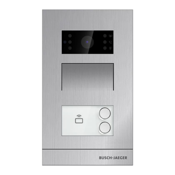
Product description Control elements Description Indicator flashes slowly: ringing Indicator flashes quickly: busy line Call indicator Unlock indicator Speaker and microphone integration Round pushbutton │7 Product manual 2TMD042200D0021... -
Page 8: Terminal Description
Product description Terminal description EXIT AGND LOCK NC COM NO GND DC+ Description Connector for the sensor used for door status detection Connector for exit button Plug-in clamps (LOCK...AGND) for door opener Plug-in clamps (COM...NC...NO) for floating output Plug-in clamps (DC+...GND) for standalone power supply LAN (PoE) │8 Product manual 2TMD042200D0021... -
Page 9: Lock Type And Connection
Product description Lock type and connection Lock type Operation type Voltage Wiring type Electrical strike ⎓ Power on to open Type A/B 12 V lock, 12V Electrical strike ⎓ Power on to open Type B 24 V lock, 24V Electrical rim ⎓... -
Page 10: Technical Data
Technical data Technical data Designation Value ⎓ Rating voltage 24 V ⎓ Operating voltage range 20-27 V ⎓ 27 V , 310 mA Rating current ⎓ 24 V , 350 mA Operating temperature -40 °C…+55 °C 99 mm x 168 mm × 26 mm (H8131.P.-.) Product dimensions 105 mm x 180 mm ×... -
Page 11: Mounting/Installation
Mounting/Installation Mounting/Installation Warning Electric voltage! Dangerous currents flow through the body when coming into direct or indirect contact with live components. This can result in electric shock, burns or even death. – Disconnect the mains power supply prior to installation and/or disassembly! –... -
Page 12: Mounting
Mounting/Installation Mounting 7.2.1 Preparation Use gloves to protect yourself against cuts. 7.2.2 Installation height 1.5 m 5 feet │12 Product manual 2TMD042200D0021... -
Page 13: Installation Situation
Mounting/Installation 7.2.3 Installation situation Note The following installation situations must be avoided without fail to ensure picture quality: ■ Direct light ■ Direct sunlight ■ Extremely bright picture background ■ Highly reflective walls on the opposite side of the door station │13 Product manual 2TMD042200D0021... -
Page 14: Surface-Mounted Installation
Mounting/Installation 7.2.4 Surface-mounted installation Product dimension 99 mm 26.5 mm 78 mm 62 mm 60 mm Surface-mounted on the wall Mount ing screw x 4 ⌀ Screw shaf t: S cre w length: ≥ 25 mm │14 Product manual 2TMD042200D0021... - Page 15 Mounting/Installation Surface-mounted on the box (e.g. VDE box) Mounting screw x 4 ⌀ S crew shaft : S cre w le ngth: 25 mm ≥ │15 Product manual 2TMD042200D0021...
-
Page 16: Flush-Mounted Installation
Mounting/Installation 7.2.5 Flush-mounted installation Product dimension 99 mm 45 mm 105 mm 53 mm 99 mm Flush-mounted with pre-installation box Mounting scre w x 4 ⌀ Screw sh aft : S cre w length: ≥ 25 mm │16 Product manual 2TMD042200D0021... -
Page 17: Cavity Wall Installation
Mounting/Installation 7.2.6 Cavity wall installation Product dimension 92 mm 105 mm 43 mm 90 mm 97 mm Mounting Mounting screw x 4 ⌀ Screw shaft : Screw le ngth: ≥ 2 5 mm │17 Product manual 2TMD042200D0021... -
Page 18: Replacing The Nameplate
Mounting/Installation 7.2.7 Replacing the nameplate │18 Product manual 2TMD042200D0021... -
Page 19: Commissioning
Commissioning Commissioning Configure the settings on indoor station 8.1.1 Outdoor station enters engineering mode Note The mini outdoor station must be on the same network as the indoor station. Unlock indicator Fi rst pushbutton P ushbutton m odule Please follow the steps below, ■... -
Page 20: Indoor Station Enters Engineering Settings
Commissioning 8.1.2 Indoor station enters engineering settings On the extra screen of indoor station, click "System" to access the corresponding screen. On the "System settings" screen, click "Engineering settings", enter the engineering password and then click "Outdoor station settings" to access the corresponding screen. │20 Product manual 2TMD042200D0021... -
Page 21: Local Device Settings
Commissioning 8.1.3 Local device settings On the "Outdoor station settings" screen, select the device type = "2nd OS". [1] Location = Internal With this setting, 2nd OS is connected to the router in the apartment. │21 Product manual 2TMD042200D0021... - Page 22 Commissioning [2] Location = External With this setting, 2nd OS is connected to the switch outside the apartment. Note The external and internal types cannot be used in mixed scenarios in the same apartment. │22 Product manual 2TMD042200D0021...
-
Page 23: Lock Management
Commissioning 8.1.4 Lock management On the "Outdoor station settings" screen, Function Unlock type when swiping Set the lock to be released when swiping. ■ Default lock (default) ■ Subsidiary lock. Lock type Set the lock type for the default lock and subsidiary lock. ■... -
Page 24: Door Status Detection
Commissioning 8.1.5 Door status detection Go to the "Outdoor station settings" screen. Function Door status detection If this function is enabled, the outdoor station will send an alarm to the management software if the door is open longer than 120 s (a sensor should first be connected to the outdoor station). Tamper proof alarm If this function is enabled, the outdoor station will send an alarm to the management software if the outdoor station is removed from the wall. -
Page 25: Sound Setting
Commissioning 8.1.6 Sound setting Go to the "Outdoor station settings" screen. Function Volume of outdoor station Click "+" or "-" to adjust the ringtone volume and the voice volume on the outdoor station. Button tone Tick the checkbox to enable button tones on the outdoor station. Voice prompt ■... -
Page 26: Anti-Flicker Setting
Commissioning 8.1.7 Anti-flicker setting On the "Outdoor station settings" screen, select the refresh rate from the drop-down list. │26 Product manual 2TMD042200D0021... -
Page 27: Set The Function Of Pushbutton
Commissioning 8.1.8 Set the function of pushbutton On the "Outdoor station settings" screen, click "Push-button address setting" to access the settings of the pushbuttons. Note Device no. should be entered if "Phone guard unit" is selected. │27 Product manual 2TMD042200D0021... -
Page 28: Time Sync Setting
Commissioning 8.1.9 Time sync setting On the "Outdoor station settings" screen. If "Sync with mgmtc." is selected, the outdoor station will sync the time from the management software. If "Close time sync" is selected, the time and date need to be set manually. │28 Product manual 2TMD042200D0021... -
Page 29: Compatible Mode Setting
Commissioning 8.1.10 Compatible mode setting On the "Outdoor station settings" screen, the outdoor station is set to "Security mode" by default (Compatible mode = off). │29 Product manual 2TMD042200D0021... -
Page 30: Updating The Firmware
Commissioning 8.1.11 Updating the firmware Note The outdoor station doesn’t need to enter engineering mode when you want to upgrade the firmware. On the "Outdoor station settings" screen, click "Firmware update", select the outdoor station and the file from SD card, then click "OK" to update the firmware. │30 Product manual 2TMD042200D0021... -
Page 31: Viewing The Version
Commissioning 8.1.12 Viewing the version On the "Outdoor station settings" screen, view the version information. │31 Product manual 2TMD042200D0021... -
Page 32: Serial Number
Commissioning 8.1.13 Serial number On the "Outdoor station settings" screen, view the serial number, this number is used to get the signature from the management software. │32 Product manual 2TMD042200D0021... -
Page 33: Signature
Commissioning 8.1.14 Signature On the "Outdoor station settings" screen, view the signature. │33 Product manual 2TMD042200D0021... -
Page 34: Configure The Settings On Smartap
Commissioning Configure the settings on SmartAP 8.2.1 Adding mini outdoor station Note Only a mini outdoor station without a certificate can be added by SmartAP. This mini outdoor station will lose its certificate if its physical address is changed. The mini outdoor station needs to be powered on before being added. On the "Smart Access Point"... -
Page 35: Configure The Settings
Commissioning 8.2.2 Configure the settings On the configuration screen, click "Door entry system", "Outdoor stations", then click a mini outdoor station to access the settings. │35 Product manual 2TMD042200D0021... - Page 36 Commissioning Basic information Function Device ID Click the icon to return to the previous screen Overview of the outdoor station Device type of the outdoor station Display the address of the outdoor station Display the serial number of the outdoor station Display the version of the outdoor station │36 Product manual 2TMD042200D0021...
- Page 37 Commissioning Additional settings Function Set the physical address for the outdoor station. Set the unlock time for default lock and subsidiary lock. Enable or disable the time synchronization with the management software. Update the firmware via local PC. Update the firmware via the external website. Set the trusted devices for the outdoor station.
- Page 38 Commissioning Set the door lock time If the default lock type is set to "IP actuator", follow the steps below, │38 Product manual 2TMD042200D0021...
- Page 39 Commissioning On the designated IP actuator screen, follow the steps below; │39 Product manual 2TMD042200D0021...
- Page 40 Commissioning │40 Product manual 2TMD042200D0021...
- Page 41 Commissioning Set the trusted devices On the designated mini outdoor station screen, follow the steps below; Note You need to enable the "Trust this management software" function if you want this outdoor station to unlock in the event of an emergency. │41 Product manual 2TMD042200D0021...
-
Page 42: Card Management
Commissioning Card management Note It is recommended that ID cards are created and maintained using local outdoor station or management software only. 1. Card management on local outdoor station Programming The system will take the first card swiped after powering up the system within 60s as the admin card. - Page 43 Commissioning During setting, please swipe the same admin card. Function Action Unlock indicator Swipe admin card 1x or no Exit settings cards swiped within 15 seconds Function Action Unlock indicator Open a door Swipe the enrolled keycard Green Technical data of ID card Work frequency Standard 125KHz...
-
Page 44: Restoring To Factory Default
Commissioning Restoring to factory default Please follow the steps below: [1] Power on the device and wait a while 3 LED indicators will turn off. [2] Then press and hold the 1st button for 3 seconds within 30 seconds until 3 LED indicators begin to flash green at the same time to indicate the device enters configuration mode. -
Page 45: Cyber Security
Cyber security Cyber security Disclaimer These products are designed to be connected and to communicate information and data via a network interface, which should be connected to a secure network. It is customer‘s sole responsibility to provide and continuously ensure a secure connection between the product and customer‘s network or any other network (as the case may be) and to establish and maintain appropriate measures (such as but not limited to the installation of firewalls, application of authentication measures, encryption of data, installation of antivirus programs, etc.) to protect... -
Page 46: Deployment Guideline
Cyber security Deployment guideline All devices need to work in security mode by default and. all devices in one system shall be signed by a public CA at commissioning stage, normally management software acts as CA. It’s suggested that compatible mode only to be used when device needs to communicate with previous generation products. -
Page 47: Notice
Notice Notice We reserve the right to at all times make technical changes as well as changes to the contents of this document without prior notice. The detailed specifications agreed to at the time of ordering apply to all orders. Busch-Jaeger accepts no responsibility for possible errors or incompleteness in this document. - Page 48 Busch-Jaeger Elektro GmbH A member of the ABB Group Freisenbergstraße 2 58513 Lüdenscheid www.BUSCH-JAEGER.de info.bje@de.abb.com Central sales service: Tel.: +49 2351 956-1600 Fax: +49 2351 956-1700 © Copyright 2022 Busch-Jaeger Elektro GmbH All rights reserved...