Table of Contents
Advertisement
Quick Links
Jun. 2021
Cautionary Notes
Before beginning the procedure, please read through this document. The matters described may differ
according to the model.
About the Serial Number
On this product, the serial number is displayed in the Test Mode and is written
to the main board using the dedicated application. The serial number is also
written on the sticker affixed inside the battery box.
Back Up User Data!
User data may be lost during the course of the procedure. Refer to Data
Backup and Restore Operations (p. 6) in the Service Notes and save the data.
After completing the procedure, restore the backed-up data to the product.
Parts List
A component whose part code is ******** will not be supplied as a service part
because one of the following reasons applies.
• Because it is supplied as an assembled part (under a different part code).
• Because a number of circuit boards are grouped together and supplied as
a single circuit board (under a different part code).
• Because supply is prohibited due to copyright restrictions.
• Because reissuance is restricted.
• Because the part is made to order (at current market price).
• Because it is carried in electronic data on the Roland web site.
• Because it is a package or an accessory irrelevant to the function
maintenance of the main body.
• Because it can be replaced with an article on the market. (battery or etc.)
• Because it is sold as a product.
SERVICE NOTES
Issued by RJA
Circuit Diagram
In the circuit diagram, "NIU" is an abbreviation for "Not in Use," and
"UnPop" is an abbreviation for "Unpopulated." They both mean non-mounted
components. The circuit board and circuit board diagram show silk-screened
indications, but no components are mounted.
There are cases that the circuit diagrams are omitted. This omission will
happen to the highly integrated digital circuit boards (e.g. Main Board etc) that
are virtually impossible to repair nor analyze.
Roland Japan Warranty
Please send the problem report with followings when the defect occurred
within one year from production and within one month from the first
customer's purchase.
• Model name:
• Serial number:
• Version:
• Purchase date by the first customer: yyyy/mm/dd
• Symptom:
• Frequency: always, sometimes or seldom
• Confirmed the symptom at your service dept: Yes/No
Please send the problem report to rjasc@roland.co.jp.
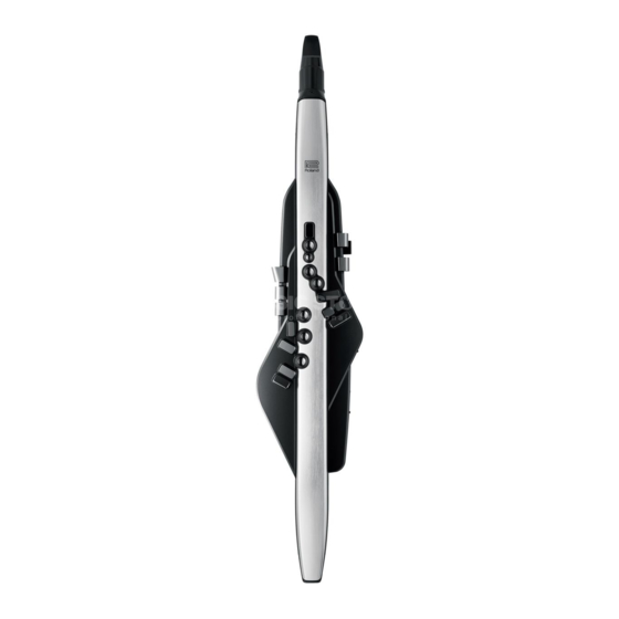
AE-30
CC-OKN
Advertisement
Table of Contents

Related Manuals for Roland AE-30


Summary of Contents for Roland AE-30
- Page 1 • Because the part is made to order (at current market price). • Confirmed the symptom at your service dept: Yes/No • Because it is carried in electronic data on the Roland web site. • Because it is a package or an accessory irrelevant to the function Please send the problem report to rjasc@roland.co.jp.
-
Page 2: Specifications
* Printed matters will not be supplied after the end of the production. Then, Connectors download the electronic file from the Roland web site. PHONES jack: stereo miniature phone type * In the interest of product improvement, the specifications and/or appearance of OUTPUT jack: stereo 1/4-inch phone type this unit are subject to change without prior notice. -
Page 3: Disassembly Procedure
Jun. 2021 AE-30 Disassembly Procedure Replacing the Bender Board When replacing the Bender Board, verify that the Bender Lever is Remove the screws v (x 10) securing the Bottom Case. (Plain View (1), inserted all the way into the Volume. If the Bender Lever is not inserted View 1) all the way, a problem such as faulty contact may be occurred. - Page 4 Jun. 2021 AE-30 Attaching the Rubber Tube Attaching the Panel-Center Board Give attention to the following points when securing the Tube When securing the Panel-Center Board to the Top Case, use two types of Escutcheon to the Bottom Case using the screws c (x 2). (Plain view (2), screws.
- Page 5 Jun. 2021 AE-30 About Application of Grease About Peripheral Sheet Assy (#5100073057) When replacing the key or the key base, apply a small amount of grease (#5100032252) to the locations shown in the figure below using a brush. Peripheral Sheet Assy (#5100073057) consists of a Panel-Center, Pedal- Be sure to verify the operation of the key after applying grease.
-
Page 6: Verifying The Version
Hold down MENU and turn on the power. Turn on the power. Continue to hold down MENU until the Roland logo disappears. The power LED lights up and the scene screen is displayed. Connect the USB memory device containing the backed-up data to the * The Power switch is on the right hand side, when you have the body stand up USB connector on the unit. -
Page 7: Performing A Factory Reset
Factory Reset and press MENU. • USB cable (Type C <--> Type A) A confirmation screen is displayed. • AE-30 driver To execute the factory reset, press to select YES. To cancel it, press * Obtain this from the following web page, and install it on the computer just to select NO. -
Page 8: Test Mode
13. Verify that AE-30 are displayed at MIDI IN Devices and MIDI OUT Devices in the application screen on the computer. * If AE-30 is not displayed, check whether the USB driver is installed correctly. 14. Input the serial number written down in step 6 to Input No.. - Page 9 Jun. 2021 AE-30 1. VERSION 5. LED This verifies the program version. This checks whether each LED lights up correctly. fig.test1.eps fig.test5.eps VERSION 01/14 05/14 App: *.**(****) ON Power LED Press to switch the CPU Program, Snd or WAVE ROM 0/ The power LED lights up orange and the LED goes off.
- Page 10 Jun. 2021 AE-30 7. AD Release your finger and verify that the bender returns to the center automatically and the value displayed on the lower line of the screen is within the range from 110 to 140. 7-1. Bite Sensor 10.
- Page 11 Jun. 2021 AE-30 7-5. 12-point Click Volume Press The following screen is displayed. Verify that sounds are coming out This checks the operation of the volume with 12 clicks. from the on-board speaker (R), not from the on-board speaker (L).
- Page 12 12. Press When pairing succeeds, Connected is displayed on the right of AE-30 Audio ** and the screen display of AE-30 is changed from A2DP:-- to The following screen is displayed. Verify that no sounds are coming out from the L/R sides of the headphones.
- Page 13 Jun. 2021 AE-30 12. USB HOST This checks the operation of the USB connector (MEMORY). fig.test12.eps USB HOST 12/14 Attach Memory Up Connect the USB memory device to the USB connector. Detach Memory is displayed on the screen. Detach the USB memory device.