
Related Manuals for Echelon FT 6000

Summary of Contents for Echelon FT 6000
- Page 1 FT 6000 EVB Develop, prototype, test, and debug applications Hardware Guide using the FT 6000 EVB. 078-0504-01A...
- Page 2 Parts manufactured by vendors other than Echelon and referenced in this document have been described for illustrative purposes only, and may not have been tested by Echelon. It is the responsibility of the customer to determine the suitability of these parts for each application.
-
Page 3: Table Of Contents
Connecting the FT 6000 EVB Hardware .......... 1 Connection Instructions ................... 2 FT 6000 EVB Hardware Details ............5 Introduction to FT 6000 EVB Hardware Details ..........6 Neuron Core ....................6 I/O Devices ....................7 Push Button Switches ................. 7 LEDs .................... -
Page 4: Preface
Preface The FT 6000 EVB is a development board for evaluating the Echelon platform for the Industrial Internet of Things (IzoT). The platform consists of chips, stacks, modules, routers and management software. The FT and Neuron 6000 family of chips enable the creation of the most compact and cost-effective IzoT capable devices. -
Page 5: Welcome
Welcome The FT 6000 EVB is a complete Series 6000 device that you can use to evaluate the Echelon platform and create IzoT™ capable devices. The FT 6000 EVB includes an FT 6000 Smart Transceiver with an external 10 MHz crystal (you can adjust the system’s internal clock speed from 5MHz to 80MHz), an FT-X3 communication transformer, external serial flash memory device, and a 3.3V power source. -
Page 6: Content
• Network cable. The network cable lets you interconnect your FT 6000 EVBs, and it lets you connect the boards to other devices and to the IzoT Router over a L FT-10 channel. ORKS • FT 6000 sample chips Content This guide includes the following content: •... - Page 7 Echelon support and training services. www.echelon.com/support You can also view free online training or enroll in training classes at Echelon or an Echelon training center to learn more about developing devices. You can find additional information about device development training at www.echelon.com/training.
- Page 8 Region Languages Supported Contact Information Other Regions English Phone: +1-408-938-5200 Japanese Fax: +1-408-328-3801 lonsupport@echelon.com viii Preface...
-
Page 9: Connecting The Ft 6000 Evb Hardware
Connecting the FT 6000 EVB Hardware This chapter describes how to power your FT 6000 EVB and connect it to your development computer. FT 6000 EVB Hardware Guide... -
Page 10: Connection Instructions
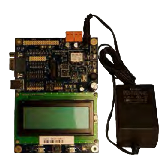
EVK. The development tool software is available by download. Connect the barrel connectors of the included power supplies into the barrel jacks on the FT 6000 EVBs, connect the power supplies to the included power cords that are appropriate for your region (US/Japan or Continental European), and then plug the power cords into a power outlet. - Page 11 IzoT NodeBuilder User’s Guide. In the quick-start exercise, you will develop a device with one sensor and one actuator. The sensor is a simple sensor that monitors a push button on the FT 6000 EVB and toggles a network variable output each time the button is pressed. The actuator drives the state of an LED on the FT 6000 EVB based on the state of a network variable input.
- Page 12 Interoperable Self-installation (ISI) mode by default. You install and connect this example application and the other examples using the OpenLNS Commissioning tool or using the ISI protocol. See the FT 6000 EVB Examples Guide for more information on using these example applications.
-
Page 13: Ft 6000 Evb Hardware Details
FT 6000 EVB Hardware Details This chapter describes the Neuron core, service pin and reset buttons and LEDs, I/O devices, and jumper settings on the FT 6000 EVB hardware. FT 6000 EVB Hardware Guide... -
Page 14: Introduction To Ft 6000 Evb Hardware Details
Documentation, and then click FT 6000 EVB Schematics. Neuron Core The Neuron core of the FT 6000 EVB includes the FT 6000 Smart Transceiver with an external 10 MHz crystal (you can adjust the system’s internal clock speed from 5MHz to 80MHz), an FT-X3 communication transformer, and an external serial flash non-volatile memory device. -
Page 15: I/O Devices
The FT 6000 EVB includes two push-button switches. The switches are labeled SW1 and SW2. The SW1 push button is connected to the IO9 pin on the FT 6000 Smart Transceiver. The SW2 push button is connected to a 74HC165 8-bit parallel-in/serial-out shift register, and data is shifted on the FT 6000 Smart Transceiver IO4 (clock) and IO5 (data) pins, with a latch strobe on IO6 (active low to capture). -
Page 16: Lcd
No. SKQUCAA010). The joystick is connected to a 74HC165 8-bit parallel-in/serial-out shift register, and data is shifted on the FT 6000 Smart Transceiver IO4 (clock) and IO5 (data) pins, with a latch strobe on IO6 (active low to capture). For more information about this joystick, go to the ALPS Web site at www3.alps.com/WebObjects/catalog.woa/E/HTML/Switch/Tact/SKQU/SKQUAAA010.html. -
Page 17: Jumper Settings
The JP23 shrouded connector provides support for third-party in-circuit device programmers, which you can use to update the data in the external serial flash device used by the FT 6000 Smart Transceiver on the FT 6000 EVB. This provides an alternative to loading application images into the external serial memory device over the TP/FT-10 network. - Page 18 To perform in-circuit programming of the external serial flash memory device on the FT 6000 EVB, follow these steps: Power off the FT 6000 EVB. Plug the Aardvark programmer pod's ribbon cable connector into the EVB's shrouded header JP23. The ribbon cable connector and JP23 are polarized to ensure proper connector orientation.
-
Page 19: I/O Line Access (Jp24)
I/O Line Access (JP24) This header provides access to the 12 I/O, service, and reset lines of the FT 6000 Smart Transceiver on the FT 6000 EVB, and it provides a ground reference for instrumentation with a scope or logic analyzer. - Page 20 This set of jumpers is used to connect the LCD, Light Sensor, LEDs, and the shift register for the SW2 push button (lines 1 and 2 of three) and joystick (SW3) on the FT 6000 EVB. The 13-14 and 15-16 pins on JP31 are used with the 1-2 pins on JP32 for bitshift I/O with the SW2 push button and the Joystick.
-
Page 21: Switch, Joystick, Temperature Sensor, & Usb Connections (Jp32)
JP203 JP32 The following table lists the I/O pins and I/O devices associated with the jumpers on JP31. Jumper I/O Pin I/O Device/Functionality on FT 6000 EVB SCL LCD SCL L Light sensor SDA LCD SDA L Light sensor 9-10... - Page 22 USB interface jumpers are disconnected as illustrated in the figure below. You can use an I/O line for other I/O functions by disconnecting the jumper that connects the I/O line to an I/O device on the FT 6000 EVB. JP204...
-
Page 23: Connecting The Usb Interface
PD (connects a 499 Ω pull-down resistor to IO9) Connecting the USB Interface You can enable serial communication without handshake lines and then connect your FT 6000 EVB to your development computer via a USB interface. This lets you perform application-level debugging, tests, or diagnosis. -
Page 24: Configuring A Device Application For Serial Debugging
Configuring a Device Application for Serial Debugging, for how to configure your device application for application-level debugging. Note: You can use only one of the EIA-232 or USB interfaces on the FT 6000 EVB at a time. For information on implementing serial I/O, see the EIA-232C Serial Interfacing with the Neuron Chip engineering bulletin (005-0008-01D). -
Page 25: Lcd 5V Power (Jp33)
LCD 5V Power (JP33) This jumper provides 5V power for the LCD on the FT 6000 EVB. If you are using the FT 6000 EVB example applications or you are developing a device application that uses the LCD, leave this jumper... -
Page 26: Eia-232 Interface (Jp201And Jp203)
JP32 If you are not using the LCD and you want to reduce the power consumption of the FT 6000 EVB, you can disconnect the LCD’s power as illustrated in the following figure (you can hang the shunt off pin 1... -
Page 27: Connecting The Eia-232 Interface (Without Handshake Lines)
Connect the male end of a DB9 Male-Female Serial Extension Cable to the DB9 socket on the upper left-hand side of the FT 6000 EVB, and then connect the female end to one of the COM ports (typically COM1 or COM2) on your computer. -
Page 28: Connecting The Eia-232 Interface (With Handshake Lines)
Note: You can use only one of the EIA-232 or USB interfaces on the FT 6000 EVB at a time. For information on implementing serial I/O, see the EIA-232C Serial Interfacing with the Neuron Chip engineering bulletin (005-0008-01D). - Page 29 Connect jumpers 5-6 (IO0 T2IN) on JP203 to route the IO0 signal through the EIA-232 interface level shifter. This signal is connected to the CTS~ signal on the EIA-232 interface. You can connect the RTS~ signal from the EIA-232 interface to the IO4 input on the FT 6000 Smart Transceiver using jumper 3-4 on JP201.
-
Page 30: I/O Connector
JP203 I/O Connector The following figure shows the I/O connector pinout for the FT 6000 EVB board. You can use this connector to attach custom I/O devices to an evaluation board. P201 IO10 IO11 SVC- RST- VDD_GIZMO VA (PWR_IN) VDD5_EXT... - Page 31 EN 55022) applies. In the North American market, the FCC regulates emissions from unintentional radiators under 47CFR15.109, Subpart B, which allows for substitution of CISPR 22. The FT 6000 EVB boards comply with CISPR 22 Level A, but not Level B (which is required for deployment in home and commercial environments).
- Page 32 FT 6000 EVB Hardware Details...
-
Page 33: A Emulating An Ft-6010 Board
Emulating an FT-6010 Board This appendix gives you the instructions for using the FT 6050 EVB to emulate an FT 6010 board. FT 6000 EVB Hardware Guide... -
Page 34: Emulating An Ft-6010 Board
I2C/SPI Host Adaptor. Alternatively, you may restore the FT 6050 EVB by loading the b6050v4.evb.ndl image over the network. WARNING: Do not ever attempt to load the b6050v4.evb.ndl into a real FT 6010 device. Doing so is unrecoverable over the network. FT 6000 EVB Hardware Details...