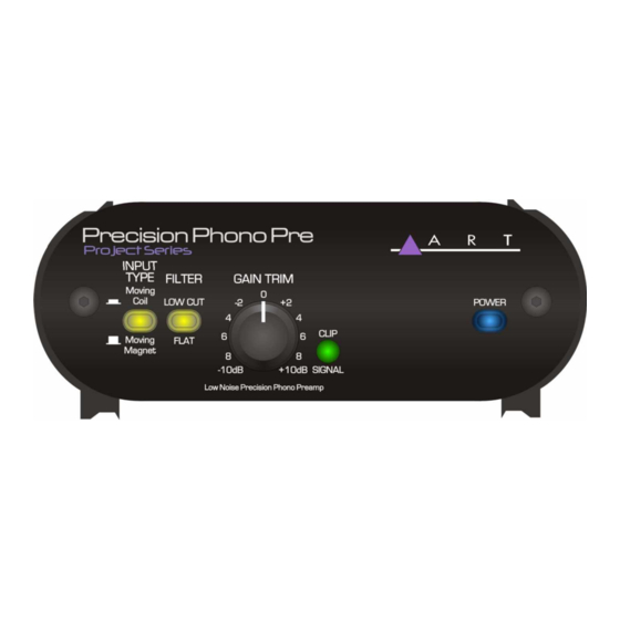
Art Project Series User Manual
Tube preamp/opto compressor-limiter/di
Hide thumbs
Also See for Project Series:
- User manual (29 pages) ,
- User manual (15 pages) ,
- User manual (12 pages)
Table of Contents
Advertisement
Quick Links
Advertisement
Table of Contents

Summary of Contents for Art Project Series
- Page 1 Tube MP/C Tube Preamp/Opto Compressor-Limiter/DI Project Series User’s Manual...
-
Page 2: Important Safety Instructions - Read First
IMPORTANT SAFETY INSTRUCTIONS – READ FIRST This symbol, wherever it appears, This symbol, wherever it appears, alerts alerts you to the presence of uninsulated you to important operating and maintenance dangerous voltage inside the enclosure. Voltage instructions in the accompanying literature. that may be sufficient to constitute a risk of shock. - Page 3 INTRODUCTION Thank you for purchasing Applied Research and Technology’s Tube MP/C. You’ve undoubtedly noticed that the Tube MP/C is as cool sounding as it looks. After getting familiar with the Tube MP/C, you’ll realize what a great investment you’ve just made. The Tube MP/C may be used everywhere! Anywhere you need level adjustments (gain or attenuation), and anywhere you need compression - you’ll be using the Tube MP/C.
- Page 4 OVERVIEW The Tube MP/C (Preamplifier/Compressor) is a multi-purpose tool for audio engineering and recording. Enclosed in a table-top chassis are two independent circuits featuring a tube-based analog preamplifier and a VCA-less compressor with optical gain reduction control. Used as a mic/line preamp or as a DI (direct) box, the Tube MP/C is designed to work seamlessly with any recording, sound-reinforcement, or electronic instrument setup.
-
Page 5: Ac Power Hookup
Hz. Only use the adapter that came with the Tube MP/C. If the adapter becomes lost or damaged, contact ART Customer Service for replacement. If you need to purchase one locally, please refer to the label on the adapter or the specifications later in this manual for the appropriate power specifications. -
Page 6: Audio Connections
Audio Connections Audio connections to and from the Tube MP/C are balanced XLR (Pin 2 Hot (+), Pin 3 Cold (-), Pin 1 Ground) and unbalanced ¼-inch (Tip Hot (+), Sleeve Ground.) We recommend using only high-quality cables equipped with the appropriate connectors. Installation The Tube MP/C may be employed in a number of setups including: ... -
Page 7: Front Panel Controls And Indicators
FRONT PANEL CONTROLS & INDICATORS Figure 1 - Front view GAIN control The Gain control sets the amount of input gain of the Tube MP/C. Turn the control clockwise to increase gain and counterclockwise to decrease gain. Selection of the gain range is made with the +20dB gain switch. You may control two ranges of gain with this control, +20 to +60dB and +0 to +40dB. -
Page 8: Threshold Control
LED is labeled “Clip.” This LED will light approximately 6dB before audible distortion occurs. If this light flickers, do not panic. The unique design of the Tube MP/C allows the tube to distort well before any other gain stage. When a tube goes into distortion it is a gradual process and tends to sound pleasing for a range before it turns into a distortion box. -
Page 9: Output Control
incorrectly, when used with a properly wired cable the signal will be out of phase. Note: for single microphone applications, switching the phase switch in and out will produce little to no change in the output signal. OPTO COMP switch An Opto Comp Bypass switch is included on the Tube MP/C to enable you to remove the compressor from your signal chain. -
Page 10: Rear Panel Functions
REAR PANEL FUNCTIONS Figure 2 - Rear view POWER switch The Power switch supplies and removes power from the unit. The Tube MP/C should be turned “on” only when all monitor levels are turned down, or off, to protect against any “thumping” caused by high gain settings. Likewise, the Tube MP/C should be turned “off”... -
Page 11: Output Switch
OUTPUT switch The Output switch controls the output level at both output jacks. The Inst. position is intended for applications where the ¼-inch output connects to an instrument input and/or the XLR output connects to a Mic input on a console. The Line setting provides more gain and maximum output level at both jacks. - Page 12 APPLICATIONS The main application of the Tube MP/C is as a microphone preamplifier and compressor. To use the Tube MP/C as a mic or line preamplifier only, simply release the Opto Comp switch to bypass the compression circuitry. Plug any microphone directly into either input and set the input and output controls to provide an appropriate level into the next stage of your system.
-
Page 13: Special Effects
Special Effects For industrial, metal, or just “flavor” textures, experiment with the Tube MP/C. Overdriving the preamp and compressor circuitry can add interesting textures when blended with vocals and other instruments. Placing signals purposely out of phase can also yield interesting results. No harm will come to the Tube MP/C with this type of experimentation. -
Page 14: Warranty Information
If you believe that the ART unit is at fault, go to www.artproaudio.com.Select “Support”, then “Return Authorization Request” to request a return authorization number. If you are returning the unit for service, pack the unit in its original carton or a reasonable substitute. The original packaging may not be suitable as a shipping carton, so consider putting the packaged unit in another box for shipping. -
Page 15: Specifications
12V DC @ ≥ 800mA Dimensions (HWD) 1.75-inch x 5.9-inch x 6.5-inch (44.5mm x 150mm x 165mm) Weight 2.9 lbs. (1.32 kg) Note: 0 dBu = 0.775Vrms ART maintains a policy of constant product improvement. Therefore, specifications are subject to change without notice. - Page 16 www.artproaudio.com E-mail: support@artproaudio.com 2021 Applied Research & Technology/ Yorkville Sound TubeMP/C 131a-5004-105...


