Table of Contents
Advertisement
Quick Links
Advertisement
Table of Contents

Related Manuals for Barrus Shire 15 70WB


Summary of Contents for Barrus Shire 15 70WB
- Page 1 WORKBOAT ENGINE MANUAL For the following engine model*: Shire 15 70WB *Standard Model, there may be a number of optional extras, or alternative components, that might be fitted to an engine that are not shown in this book. RDG603A81 – Issue 2...
- Page 2 SAFETY E.P. Barrus is concerned for your safety. We use safety statements throughout the manual to call your attention to the potential hazards associated with the operation of your Shire engine. Follow the precautions listed throughout the manual before operation, during operation and during servicing/maintenance procedures for your safety, the safety of others and to protect the performance of your engine.
- Page 3 Shire Engine Manuals and Shire Parts Books To access the Shire Engine Manuals and Shire Parts Books on the internet type the following short links into your search engine: https://www.barrus.co.uk/shire-manuals/ https://www.barrus.co.uk/shire-parts/ RDG603A81 – Issue 2 Page 3 of 93...
- Page 4 The information and recommendations given in this manual are based on the latest information available at the time of publication. E.P.Barrus reserve the right to change the specification of its products and manuals without prior notice.
- Page 5 Routine maintenance outlined in the Owner’s Manual must be performed using genuine parts in order to maintain warranty coverage. If the customer performs maintenance, Barrus reserves the right to make future warranty coverage possible only with proof of proper maintenance.
- Page 6 WARRANTY CLAIMS Warranty claims shall be made by an authorised dealer or boat builder. The dealer or boat builder will then arrange for the inspection and any necessary repairs. If the repairs carried out are not covered by the warranty, the purchaser shall pay for all related labour and material, and any other expenses associated with that service.
-
Page 7: Table Of Contents
Index Page SECTION 1 – Safety Precautions ..................11 General ........................11 Lifting .........................11 Rotating Shafts and Belts ..................11 Exhaust System ......................12 Launching and Lifting Boats..................12 Batteries........................12 SECTION 2 – Engine Identification...................14 SECTION 3 – Component Identification ................15 Shire 70 Work Boat ....................15 SECTION 4 –... - Page 8 Engine Oil ........................26 Fuel ..........................26 Coolant ........................28 Control Cables ......................29 Domestic Battery Bank ....................29 Seawater Strainer ......................30 Control Panel ......................30 Exhaust System ......................31 Hydraulic Drive Transmissions ..................35 Hydraulic Pump Drive Option (Shire 70WB) ..............35 PRM 280DP Gearbox with Power Take Off (Option - RDG914A198) ......36 Engine Start Battery ....................36 Installation Check List ....................37 SECTION 6 –...
- Page 9 Fuel System Bleeding ....................46 Cooling System ......................46 Belt Adjustment ......................47 Belt Maintenance .......................48 Belt Replacement ......................48 Control Panel Maintenance..................49 Sacrificial Anode Change...................50 Raw Water Pump Impeller Change ................50 Engine Heat Exchanger Tube Stack Flushing ............50 Winterisation of Seawater Cooling System ..............51 SECTION 8 –...
- Page 10 SECTION 15 – Declarations ....................69 Declaration of Conformity for Recreational Craft Propulsion Engine with the requirements of Directive 2013/53/EU.................69 Declaration of Conformity for Recreational Propulsion Engine with the requirements of the Recreational Craft Regulations 2017 (UKCA Marking)..........70 Declaration of Incorporation of Partly Completed Machinery ........71 EU Declaration of Conformity with the Exhaust Emissions Requirements of Directive 2013/53EU ...........................75 SECTION 16 –...
-
Page 11: Section 1 - Safety Precautions
SECTION 1 – Safety Precautions 1. General NOTICE: NEVER PERMIT ANYONE TO OPERATE THE ENGINE WITHOUT PROPER TRAINING. It is the responsibility of the installer/operator to ensure that the finished installation complies with CE Marking, UKCA Marking, relevant Health & Safety Requirements, the Recreational Craft Directive and or any other legislative requirements before commissioning. -
Page 12: Exhaust System
The engine and its accessories are not intended to be put into operation until they are integrated into the boat as a whole. No person should be in the engine compartment and the engine cover or deck hatches should be closed whilst the engine is running. 4. - Page 13 WARNING: BURN HAZARD! BATTERIES CONTAIN SULPHURIC ACID. NEVER ALLOW BATTERY FLUID TO COME IN CONTACT WITH SKIN, EYES OR CLOTHING. SEVERE BURNS COULD RESULT. MAKE SURE THE CORRECT PERSONAL PROTECTION EQUIPMENT IS WORN. • Batteries can produce explosive gases; keep sparks and flames away from the battery. NO SMOKING •...
-
Page 14: Section 2 - Engine Identification
SECTION 2 – Engine Identification The engine serial number can be found engraved into the brass plate on the top of the engine rocker cover and stamped to the crankcase next to the starter motor. An example of the engine identification plate is shown below (Figure 1): Description Engine Model Serial Number... -
Page 15: Section 3 - Component Identification
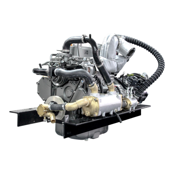
SECTION 3 – Component Identification 1. Shire 70 Work Boat Description* Coolant Heat Exhanger 50 Amp 12 Volt Alternator Seawater Pump (Crankshaft Driven) Gearbox Oil Cooler Figure 2: Shire 70 Work Boat Left Side (Viewed from front) Description* Air Filter Gearbox Oil Filter TO BE ADDED... -
Page 16: Section 4 - Control Panel
SECTION 4 – Control Panel 1. Standard Control Panel Description 1 Tachometer Gauge 2 Hour Meter 3 Water Temperature Warning Light 4 Oil Pressure Warning Light 50A Alternator Charge Warning Light 150/240A Alternator Charge Warning Light 7 Glow Plug Light 8 Key Flap and Ignition Switch Figure 4: Standard Control Panel 2. -
Page 17: Control Panel Overview
3. Control Panel Overview • All Shire engines are supplied with a control panel. • Depending on the model of Shire engine, the control panel will either be a standard control panel or a deluxe control panel. The following table shows which panel comes with each type of engine as standard. - Page 18 Description Procedure for Warning Light Tachometer Gauge Hour Meter Reduce the engine revs and stop the engine within one or two minutes. Check the coolant level (refer to 9. Cooling System of SECTION 7 - SERVICE PROCEDURE). If the coolant level is incorrect, fill it to the correct level (refer to 9.
-
Page 19: Overall Dimensions Of The Standard Control Panel
5. Overall Dimensions of the Standard Control Panel (All Dimensions are in mm) Figure 6: Standard Control Panel Dimensions 6. Overall Dimensions of the Deluxe Control Panel (All Dimensions are in mm) Figure 7: Deluxe Control Panel Dimensions RDG603A81 – Issue 2 Page 19 of 93... -
Page 20: Section 5 - Installation
SECTION 5 – Installation NOTICE: REFER TO THE SHIRE AND YANMAR MANUALS PRIOR TO INSTALLING THE ENGINE. 1. Ventilation • All internal combustion engines radiate heat and require cool, clean air to aid complete combustion. • Please ensure that adequate engine room ventilation is provided, by fitting at least two vents of an aperture of not less than 15,000mm each (24in An allowance must be made for any grills, louvres or bends placed in the... -
Page 21: Shaft Connection And Propeller Selection
• The pressurised header tank should be mounted higher than the level of the engine, no less than 300mm, and no more than 1m from the engine, to prevent cooling system air locks. • The header tank has two hose connections of different internal diameters. The smaller internal diameter hosetail (left side of tank) should be connected to the top of the thermostat housing on the engine. - Page 22 • Ensure that the anti-vibration mount centre screw is sufficiently raised so as not to touch the engine bed. If this occurs, excessive engine vibration will be experienced through the hull. • For best results, fit the front AV mounts into the front holes in the engine rails. If the engine room space is a problem the mounts can be fitted slightly further back in the alternative holes and the front of the rail cut off –...
- Page 23 Figure 10: Correct Anti-Vibration Mount Installation Description Normal mounting position Alternative mounting position if engine compartment space is restricted Figure 11: Anti-Vibration Mount Installation Points RDG603A81 – Issue 2 Page 23 of 93...
-
Page 24: Engine Alignment
7. Engine Alignment • The gearbox output shaft flange and propeller shaft input flange must be almost perfectly aligned. A maximum of 0.05mm (0.002”) misalignment in any plane is acceptable. Ensure alignment is recheck after the first 4 hours of running, after the first month and thereafter annually. -
Page 25: Electrics
9. Electrics CAUTION • Do not attach any part, hose or cable to the engine wiring harness. There is a warning label attached to the harness to remind you of this. • Connect the wiring extension harness multi plug to the panel plug and the other end to the engine. -
Page 26: Electrical Options
10. Electrical Options DANGER: ELECTRIC SHOCK RISK! • The Shire range can be supplied with other optional additional 12V, 24V or 48V alternators. This will be supplied fitted but not wired. It is the responsibility of the boat builder to ensure that this is correctly wired to the boats electrical system. 11. - Page 27 WARNING: DIESEL FUEL IS HARMFUL TO SKIN. MAKE SURE THE RELEVANT PERSONAL PROTECTION EQUIPMENT IS WORN. • Ensure the main fuel tank is clear of dirt and water. • A separate water trap must be fitted to all engine installations. The engines are supplied with an additional fuel pre-filter water trap as standard.
-
Page 28: Coolant
Figure 13: Secondary Fuel Filter Head (129004-55612-9) 13. Coolant WARNING: SCALD HAZARD! NEVER REMOVE THE COOLANT BOTTLE CAP IF THE ENGINE IS HOT. STEAM AND HOT COOLANT WILL SPURT OUT AND CAUSE INJURY. TIGHTEN THE CAP SECURELY AFTER BEING REMOVED. STEAM CAN SPURT OUT DURING ENGINE OPERATION IF THE CAP IS LOOSE. -
Page 29: Control Cables
After running the engine for the first time, stop the engine and monitor the water level frequently as trapped air bubbles may be expelled. Top up the system as necessary. 14. Control Cables • Connect engine speed control cable. With the engine off, ensure that the engine speed control lever achieves full travel from idle to full speed. -
Page 30: Seawater Strainer
alternator, maximum output current. Example 1: Live aboard application fitted with a 150amp domestic alternator 3 x 150 = 450 ampere/hour maximum battery bank size Example 2: Weekend cruising or hire fleet application fitted with a 240amp domestic alternator 3.5 x 240 = 840 ampere/hour maximum battery bank size. The standard alternators fitted to Shire engines are not suitable for charging lithium-ion batteries. -
Page 31: Exhaust System
• Confirm settings to tacho meter reader. • An optical tachometer is required to check the reading. Barrus Alternator (Amps) Barrus Tacho reading 10.50 – 11.00 Alternative or non-standard alternators will require calibrating and checking by trial and error, with a hand held tacho until the engine speed and indicated tachometer speed are the same. - Page 32 The correct installation of the lift silencer is vital to safety, and to avoid back flooding of the engine. Figure 15 shows how to install the lift silencer correctly (Note: Halyard (M&I) Limited have given Barrus permission to use the diagram). RDG603A81 – Issue 2...
- Page 33 The back pressure falls within the manufacturers recommended range when using the optional exhaust system with the engine. Barrus recommend that Halyard (M&I) Limited are used for the Lift Silencer, Siphon Break and other components. Contact Halyard (M&I) Limited for further information.
- Page 34 Connections to the silencer should be made using suitable exhaust hose, which is type approved by Lloyds and DNV. Do not use oil or grease to lubricate hoses when installing, wetting the inside of the hoses with water will help them slip more easily over the silencer spigots.
-
Page 35: Hydraulic Drive Transmissions
19. Hydraulic Drive Transmissions If an engine is to have a hydraulic drive transmission attached to it instead of a conventional marine gearbox, a number of points must be observed. • Bobtail engines (i.e. Engines supplied without a marine gearbox), normally do not have a gearbox oil cooler fitted. -
Page 36: Prm 280Dp Gearbox With Power Take Off (Option - Rdg914A198)
Ratio: 1:231 A gearbox P.T.O (Power Take Off) is available as an optional extra on all engines. 21. PRM 280DP Gearbox with Power Take Off (Option - RDG914A198) The PRM B 280 with power take off is designed for driving hydraulic pumps made to SAEJ77 Series specification. -
Page 37: Installation Check List
23. Installation Check List Please tick box Engine alignment correct, clearance all round, check propeller turns by hand (Ensure ignition is off battery and battery master switch is off) Anti-Vibration mounts correct height, spacers if necessary. Make sure all nuts are tight Exhaust system as specified Check the correct size of start battery has been fitted Battery leads are of correct size, tightened and start battery is charged... -
Page 38: Section 6 - Operation
SECTION 6 – Operation NOTICE: REFER TO THE YANMAR MANUAL PRIOR TO STARTING THE ENGINE. 1. Starting the engine for the first time • Ensure the start battery is fully charged and is of the correct specification. • Remove ignition key. •... -
Page 39: Stopping Procedure
• Once started check that sea water is coming out of the water cooled exhaust outlet in the hull of the boat. • The engine has a warm up feature which means it revs at approx. 1300 rpm when it is cold. -
Page 40: Diesel Fuel Additive
• All Shire canal boat engines run on diesel fuel. • Please note that when the vessel is to be left for any period of time, the fuel tank should be left full to eliminate the build-up of condensation and formation of water in the fuel tank. -
Page 41: Section 7 - Service Procedure
SECTION 7 – Service Procedure NOTICE: REFER TO THE YANMAR MANUAL PRIOR TO CARRYING OUT ANY SERVICE OR MAINTENANCE WORK. WARNING: PRIOR TO CARRYING OUT ANY SERVICE OR MAINTENANCE WORK MAKE SURE THE RELEVANT PERSONAL PROTECTION EQUIPMENT IS WORN. 1. Engine Oil and Filter Change WARNING: BURN HAZARD! WAIT UNTIL THE ENGINE COOLS SLIGHTLY BEFORE YOU DRAIN THE ENGINE OIL. -
Page 42: Air Filter Check And Change
2. Air Filter Check and Change • Release the two spring clips. Pull off the end cover to reveal the filter element. The element simply pulls out. • To fit the new element, slide the open end of the filter element into the main body. Gently push the element until fully seated. -
Page 43: Disposal Of Oil And Related Items
Gearbox Model Location of Dipstick / Filler Plug / Drain Plug Level dipstick & Filler Plug PRM 280 Level dipstick & Filler Plug PRM 500 Figure 16: Location of Dipstick / Filler Plug on Gearbox 4. Disposal of Oil and Related Items NOTICE: ALWAYS BE ENVIRONMENTALLY RESPONSIBLE. -
Page 44: Primary Fuel Filter Drain (Rdg9188346)
5. Primary Fuel Filter Drain (RDG9188346) WARNING: DIESEL FUEL IS FLAMMABLE AND EXPLOSIVE UNDER CERTAIN CONDITIONS. WARNING: DIESEL FUEL IS HARMFUL TO SKIN. MAKE SURE THE RELEVANT PERSONAL PROTECTION EQUIPMENT IS WORN. • Place a small drain bowl under the primary fuel filter / water trap. •... -
Page 45: Primary Fuel Filter Change
6. Primary Fuel Filter Change DANGER: DIESEL FUEL IS FLAMMABLE AND EXPLOSIVE UNDER CERTAIN CONDITIONS. WARNING: DIESEL FUEL IS HARMFUL TO SKIN. MAKE SURE THE RELEVANT PERSONAL PROTECTION EQUIPMENT IS WORN. • Ensure the fuel tank is at least ¾ full prior to undertaking this procedure. •... -
Page 46: Fuel System Bleeding
• Refer to the Yanmar Operators Manual, Periodic Maintenance. 8. Fuel System Bleeding DANGER: DIESEL FUEL IS FLAMMABLE AND EXPLOSIVE UNDER CERTAIN CONDITIONS. WARNING: DIESEL FUEL IS HARMFUL TO SKIN. MAKE SURE THE RELEVANT PERSONAL PROTECTION EQUIPMENT IS WORN. • Ensure the fuel tank is at least ¾ full prior to undertaking this procedure. •... -
Page 47: Belt Adjustment
• If required, top up the level with coolant (50% clean tap water and 50% ethylene glycol based anti-freeze) through the expansion tank filler cap. • Do not use water only to top up as this weakens the coolant mix, reducing the level of frost protection and anti-corrosion protection of the coolant. -
Page 48: Belt Maintenance
11. Belt Maintenance WARNING: SEVERE HAZARD! KEEP HANDS AND OTHER BODY PARTS AWAY FROM MOVING/ROTATING PARTS. WEAR TIGHT FITTING CLOTHING AND KEEP YOUR HAIR SHORT OR TIE BACK. REMOVE ALL JEWELLERY BEFORE COMMENCING WORK. CHECK BEFORE STARTING THE ENGINE THAT ANY TOOLS OR RAGS USED DURING MAINTENANCE HAVE BEEN REMOVED FROM THE AREA. -
Page 49: Control Panel Maintenance
• Loosen the top adjuster bolts and the lower mounting pivot nut and bolt. • Push the alternator towards the engine to loosen the belt. • Remove the belt. • Hold the belt in position over the top alternator pulley. Rotate the engine if required by hand, to guide the new belt into the “vee”. -
Page 50: Sacrificial Anode Change
14. Sacrificial Anode Change • The anode is located on the end of the heat exchanger (Figure 18) Figure 18: Shire 70WB Sacrificial Anode Location 15. Raw Water Pump Impeller Change • The pump is located on the front of the engine. It is either fitted to the Power Take Off pulley camshaft drive or bolted to the front of the engine and driven by the crankshaft. -
Page 51: Winterisation Of Seawater Cooling System
• Inspect the tube stack and replace if damaged. • Reassemble and refit, checking the end cap “O” rings are in good condition. • Ensure the end caps are fitted in the correct orientation. If they are not in the correct orientation, overheating will occur which will not be covered under the warranty. -
Page 52: Section 8 - Service Schedule
SECTION 8 – Service Schedule NOTICE: REFER TO THE YANMAR MANUAL PRIOR TO CARRYING OUT ANY SERVICE OR MAINTENANCE WORK. WARNING: PRIOR TO CARRYING OUT ANY SERVICE OR MAINTENANCE WORK MAKE SURE THE RELEVANT PERSONAL PROTECTION EQUIPMENT IS WORN. 1. Specifications and Capacities Specification of Coolants and Lubricants to use: Component Lubricant... -
Page 53: Service Intervals
2. Service Intervals Check Change Notes Every 350 Hours Engine Oil & Filter Daily (Level) First change after 50 hours OR 12 Months* Weekly Every 350 Hours Gearbox Oil First change after 25 hours (Level) OR 12 Months* Coolant Level Daily (Level) Every 24 Months At first 50 hour... -
Page 54: Section 9 - Wiring Diagrams
SECTION 9 – Wiring Diagrams 1. Engine Wiring Diagram Shire 70 Figure 19: Shire 70 Wiring Diagram RDG603A81 – Issue 2 Page 54 of 93... -
Page 55: Standard Control Panel Wiring Diagram
2. Standard Control Panel Wiring Diagram Figure 20: Standard Control Panel Wiring Diagram RDG603A81 – Issue 2 Page 55 of 93... -
Page 56: Deluxe Control Panel Wiring Diagram
3. Deluxe Control Panel Wiring Diagram Figure 21: Deluxe Control Panel Wiring Diagram RDG603A81 – Issue 2 Page 56 of 93... -
Page 57: Prestolite 24 Volt 120 Amp Alternator Wiring Diagram
4. Prestolite 24 Volt 120 Amp Alternator Wiring Diagram Figure 22: 24v 120A Alternator Wiring Before wiring the 24 Volt 120 Amp Alternator, please read the information below: • The S (Sense) terminal is not active on the AVI147J3110HD or AVI147J3113HD models so does not need connecting (on those two models). - Page 58 • The alternator is fitted with two B+ terminals. Either of the B+ terminals can be used. • The alternator is earth return (grounded) Ensure there is a good earth connection to the engine. Note: The Prestolite 24 Volt 120 Amp Alternator connects to the ‘12V Ignition on Switched Terminal' shown on the Shire 70 Engine Wiring Diagram (See 1.
-
Page 59: Section 10 - Technical Data
SECTION 10 – Technical Data 1. Engine Data Engine Model Shire 70 - TNV98 ZNSA Type Vertical In-Line Diesel Engine Combustion System Direct Injection Aspiration Naturally Number of Cylinders Bore x Stroke 98 x 110mm Displacement 3.319L Rated Output/Speed 52kW (70hp) at 2500rpm Low Idling 1000 rpm (when warm, 1300 rpm when cold) High Idling... -
Page 60: Section 11 - Fault Diagnosis
SECTION 11 – Fault Diagnosis 1. Failure Indicator Flashing Pattern • If a fault occurs with the engine, the failure indicator light (Figure 23) will start flashing. The sequence in which the failure indicator light starts to flash will indicate the fault that has occurred. - Page 61 • If an EGR valve failure is detected when the engine is started, the failure indicator light will flash in a pattern of thirteen (one long flash followed by 3 short flashes) as shown in (Figure 25) Upper: 1 flash Lower: 3 flashes When the engine is started 0.5s...
-
Page 62: Fault Codes
3. Fault Codes Fault Item Flashing Fault Code Pattern Area Status Failure (Low Voltage) P0117/4 Cooling Water Temperature Sensor Failure (High Voltage) P0118/3 Failure (Low Voltage) P0122/4 Failure (High Voltage) P0123/3 Accelerator Sensor Intermittent Failure P0124/2 Lower Limit Error P1125/1 Upper Limit Error P1126/0 Speed Sensor... - Page 63 Failure (Low Voltage) P1222/4 Rack Actuator Relay Failure (High Voltage) P1223/3 Intermittent Failure P1224/2 Failure (Low Voltage P0222/4 Failure (High Voltage) P0223/3 Intermittent Failure P0224/2 Spare Accelerator Sensor Lower Limit Error P1225/1 Upper Limit Error P1226/0 Communication Error P1227/8 Failure (Low Voltage) P2228/4 Atmospheric Pressure Sensor Failure (High Voltage)
-
Page 64: Section 12 - Dealer List
SECTION 12 – Dealer List Area Company Telephone Email Driveline Marine 0118 942 3877 tam@drivelinemarine.com Marcus Marine Engineering Ltd BERKSHIRE 07900890911 Marcus@marcusmarine.co.uk (Servicing, Repairs & Breakdowns only) BRISTOL Advance Marine 01275 815910 phil@advancemarine.co.uk Midland Chandlers 01928 751 800 preston.brook@midlandchandlers.co.uk CHESHIRE Nantwich Canal Centre Ltd 01270 625122 info@nantwichcc.com... - Page 65 LONDON Lee Valley Marina 020 88061717 springfieldmarina@vibrantpartnerships.co.uk MIDDLESEX Lindon Lewis Marine 01932 247427 service@pushtheboatout.com NORFOLK French Marine Motors Ltd 01603 722079 info@frenchmarine.com Grand Junction Boat Co. 01604 858043 info@boatrepairs.uk.com NORTHAMPTON Midland Chandlers 01788 891401 braunston@midlandchandlers.co.uk NOTTINGHAM Farndon Marina 01636 705483 info@farndonmarina.co.uk OXFORDSHIRE Service Engine UK...
-
Page 66: Section 13 - Shire Service Parts
60 amp Control Panel Supply 15 amp (RDG3245) Main Permanent Live 10 amp (RDG1437) Engine Oil: Engine oil is available from Barrus in convenient 5 litre containers. The part number is RDG6110. RDG603A81 – Issue 2 Page 66 of 93... - Page 67 RDG80210219). Shire Parts Book: On the E.P Barrus Website there is a Shire 70WB Parts Book which has a more extensive list of parts available for your engine. To access the Shire Parts Books on the internet, type the following short link into your search engine: https://www.barrus.co.uk/divisions/marine/diesel/shire/downloads/shire-parts/?p=1...
-
Page 68: Section 14 - Afterlife Recycling
SECTION 14 – Afterlife Recycling When it becomes necessary to dispose of your engine. This may be possible at recycling centre; however, it will likely require careful disassembly first before disposal. For further information please contact your local recycling centres for disposal advice to see what they will accept for disposal. -
Page 69: Section 15 - Declarations
Name of Engine Manufacturer: E.P.Barrus LTD Name of Authorised Representative: E.P.Barrus LTD Address: E.P.Barrus LTD, Launton Road, Bicester, Oxon, OX26 4UR, England, United Kingdom Name of Notified Body for exhaust emission assessment: HPi Verification Services (Ireland) Ltd Address: HPi Verification Services (Ireland) Ltd, Clonross... -
Page 70: Declaration Of Conformity For Recreational Propulsion Engine With The Requirements Of The Recreational Craft Regulations 2017 (Ukca Marking)
Name of Engine Manufacturer: E.P.Barrus LTD Name of Authorised Representative: E.P.Barrus LTD Address: E.P.Barrus LTD, Launton Road, Bicester, Oxon, OX26 4UR, England, United Kingdom Name of Notified Body for exhaust emission assessment: HPi CEproof Ltd Address: HPi CEproof Ltd, The Manor House, Howbery Park... -
Page 71: Declaration Of Incorporation Of Partly Completed Machinery
3. Declaration of Incorporation of Partly Completed Machinery (Original declaration according to Directive 2006/42/EC, Annex II, part 1B) 1. The manufacturer: E. P. Barrus Limited Glen Way Launton Road Bicester OX26 4UR England United Kingdom 2. Authorised Compiler of Mr. Graeme Aldridge... - Page 72 ANNEX A The essential health and safety requirements for machinery can only be made compliant partly by Barrus. Therefore Barrus recommends to double-check the paragraphs from Annex 1 of the Directive 2006/42/EC mentioned below for compliance with the Directive for your particular machine.
- Page 73 For the fuel filter, fuel injection pump, fuel injection nozzles, high pressure fuel injection pipes and fuel hoses supplied and installed on the engine by Barrus. Any other fuel system parts connected to the engine to be made compliant by the boat builder/installer.
- Page 74 1.5.8 Noise 1.5.9 Vibrations 1.5.10 Radiation 1.5.11 External radiation 1.5.12 Laser radiation Not applicable 1.5.13 Emissions of hazardous materials and substances Except for the exhaust, fuel, and cooling water system which needs to be properly connected by the boat builder or installer according to the Shire Manual. 1.5.14 Risk of being trapped in a machine...
-
Page 75: Eu Declaration Of Conformity With The Exhaust Emissions Requirements Of Directive 2013/53Eu
4. EU Declaration of Conformity with the Exhaust Emissions Requirements of Directive 2013/53EU (Original declaration according to Directive 2013/53/EU) The manufacturer: E. P. Barrus Limited Glen Way Launton Road Bicester OX26 4UR 2. Authorised Compiler of Mr. Graeme Aldridge Relevant Technical... -
Page 76: Section 16 - Lubricant Safety Data Sheets
SECTION 16 – Lubricant Safety Data Sheets 1. Golden Film Running In Oil SAFETY DATA SHEET Golden Film Running in oil SECTION 1: IDENTIFICATION OF THE SUBSTANCE/MIXTURE AND OF THE COMPANY/UNDERTAKING 1.1. Product identifier Product name Golden Film Running in oil Product No. - Page 77 Distillates (petroleum) solvent-dewaxed heavy paraffinic 10-30% CAS-No.: 64742-65-0 EC No.: 265-169-7 Registration Number: 01-2119471299-27 A petroleum product. DMSO extract < 3 % weight ( IP 346 ) Classification (EC 1272/2008) Classification (67/548/EEC) Not classified. Not classified. Phosphorodithioic acid, O,O-di-C1-14-alkyl esters, zinc salts <...
- Page 78 SECTION 5: FIREFIGHTING MEASURES 5.1. Extinguishing media Extinguishing media Extinguish with foam, carbon dioxide, dry powder or water fog. Unsuitable extinguishing media Do not use water jet as an extinguisher, as this will spread the fire. 5.2. Special hazards arising from the substance or mixture Hazardous combustion products In case of fire, toxic gases (CO, CO2, NOx) may be formed.
- Page 79 SECTION 8: EXPOSURE CONTROLS/PERSONAL PROTECTION 8.1. Control parameters Name TWA - 8 Hrs STEL - 15 Min Notes Distillates (petroleum) solvent-dewaxed heavy ACGIH 5 mg/m3 10 mg/m3 paraffinic Solvent refined mineral oil ACGIH 5 mg/m3 10 mg/m3 ACGIH = American Conference of Governmental Industrial Hygienists. 8.2.
- Page 80 Other Flammability Product is not flammable but on excessive heating may become combustible. Material is considered non-oxidizing. 9.2. Other information Volatility Description Not considered volatile. Vapours may be emitted on excessive heating. The product is a complex mixture, the majority of which would not be classed as a VOC. However it cannot be discounted that trace or low levels of VOC's may be present.
- Page 81 Aspiration hazard: Viscosity Kinematic viscosity > 20.5 mm2/s. The product viscosity is greater than the upper limit assigned for classification. The product contains mineral oil. If aspirated into the lungs e.g. through vomitting after ingestion admit to hospital immediately. General information This product has low toxicity.
- Page 82 SECTION 13: DISPOSAL CONSIDERATIONS General information Waste to be treated as controlled waste. Disposal to licensed waste disposal site in accordance with local Waste Disposal Authority. 13.1. Waste treatment methods Dispose of waste and residues in accordance with local authority requirements. SECTION 14: TRANSPORT INFORMATION General The product is not covered by international regulation on the transport of dangerous goods (IMDG, IATA,...
- Page 83 SECTION 16: OTHER INFORMATION Revision Comments NOTE: Lines within the margin indicate significant changes from the previous revision. Revision Date 21/05/2015 Revision 2 Supersedes date 23/08/2010 Risk Phrases In Full R53 May cause long-term adverse effects in the aquatic environment. R43 May cause sensitisation by skin contact.
-
Page 84: Ground Force 10W-40
2. Ground Force 10W-40 SAFETY DATA SHEET Ground Force 10W-40 SECTION 1: Identification of the substance/mixture and of the company/undertaking 1.1. Product identifier Product name Ground Force 10W-40 Product number 7450 Internal identification GHS21580 REACH registration number n/a Mixture 1.2. Relevant identified uses of the substance or mixture and uses advised against Identified uses Engine oil. - Page 85 SECTION 3: Composition/information on ingredients 3.2. Mixtures Distillates (petroleum) solvent-dewaxed heavy paraffinic 30-60% CAS-No.: 64742-65-0 EC No.: 265-169-7 REACH registration number: 01- 2119471299-27-XXXX A petroleum product. DMSO extract < 3 % weight ( IP 346 ) Classification Classification (67/548/EEC or 1999/45/EC) Not classified.
- Page 86 SECTION 5: Firefighting measures 5.1. Extinguishing media Suitable extinguishing media Extinguish with foam, carbon dioxide, dry powder or water fog. Unsuitable extinguishing Do not use water jet as an extinguisher, as this will spread the fire. Media 5.2. Special hazards arising from the substance or mixture Specific hazards Heat from fire could result in drums bursting Hazardous combustion...
- Page 87 SECTION 8: Exposure Controls/personal protection 8.1. Control parameters Occupational exposure limits Distillates (petroleum) solvent-dewaxed heavy paraffinic Long-term exposure limit (8-hour TWA): ACGIH 5 mg/m³ Short-term exposure limit (15-minute): ACGIH 10 mg/m³ Distillates,hydrotreated heavy paraffinic Long-term exposure limit (8-hour TWA): ACGIH Short-term exposure limit (15-minute): ACGIH 10 mg/m³...
- Page 88 8.2. Exposure controls Protective equipment Appropriate engineering Provide adequate general and local exhaust ventilation. Observe any occupational exposure controls limits for the product or ingredients. Eye/face protection Eyewear complying with an approved standard should be worn if a risk assessment indicates eye contact is possible.
- Page 89 Decomposition Temperature Not determined. Viscosity 89.4 cSt @ 40°C Explosive properties Not considered to be explosive. Explosive under the influence Not considered to be explosive. of a flame Oxidising properties The mixture itself has not been tested but none of the ingredient substances meet the criteria for classification as oxidising.
- Page 90 Carcinogenicity Carcinogenicity This product contains mineral oils which are considered to be severly refined and not considered to be carcinogenic under IARC. All of the oils in this product have been demonstrated to contain less than 3% extractables by the IP346 test Reproductive toxicity Reproductive toxicity - fertility No data available to suggest the product will cause reproductive toxicity.
- Page 91 12.5. Results of PBT and vPvB assessment Results of PBT and vPvB This product does not contain any substances classified as PBT or vPvB. assessment 12.6. Other adverse effects Other adverse effects None known. SECTION 13: Disposal considerations 13.1. Waste treatment methods General information This material and its container must be disposed of as hazardous waste.
- Page 92 15.2. Chemical safety assessment No chemical safety assessment has been carried out. Inventories Canada - DSL/NDSL All the ingredients are listed or exempt. US - TSCA All the ingredients are listed or exempt. Australia - AICS All the ingredients are listed or exempt. Korea - KECI All the ingredients are listed or exempt.
-
Page 93: Section 17 - Shire Service Record Card
SECTION 17 – Shire Service Record Card SERVICE RECORD CARD ……………………………………………………………………… Model: ……………………………………………………………….. Engine No: Carried out by E.P.Barrus Boat Builder Stamp: Print Name: Commission of Boat and Hand Over to Customer. (Refer to the Installation Check List Page in this Actual Hours: Manual).