
Related Manuals for Siemens TPS4 13


Summary of Contents for Siemens TPS4 13
- Page 1 INSTALLATION, OPERATION AND MAINTENANCE MANUAL Surge Protection Devices TPS4 13 usa.siemens.com/spd...
- Page 2 TPS4 13 TPS4 13 Installation Instructions DANGER Hazardous Voltage Will cause death or serious injury. Turn off power before working on this equipment WARNING Safety First – Hazardous Voltage and Shock Hazard • Only qualified licensed electricians should install or service SPDs •...
- Page 3 TPS4 13 TPS4 13 Catalog Logic TPS4 Catalog No. Surge Current (kA) Voltage Code Enclosure Options A = 120/240 V, 1Ø, 3W 10 = 100 kA per phase 0 = No Enclosure 2 = Type 2 SPD B = 120/240 V, 3Ø, 4W...
-
Page 4: Pre-Installation
Line Side versus Load Side Installation The TPS4 13 are tested and qualified as Type 1 SPDs per UL 1449 Fourth Edition (cUL type 2). This SPD can be installed on the Line Side of the service overcurrent device. Type 1 SPDs may also be installed in Type 2 applications. - Page 5 TPS4 13 UL 1283 required language concerning the installation of EMI Filters An insulated grounding conductor that is identical in size and insulation material and thickness to the grounded and ungrounded circuit supply conductors, except that it is green with or without one or more yellow stripes, is to be installed as part of the circuit that supplies the filter.
-
Page 6: Installation
(N-G bonding not per NEC® will fail SPDs: #1 cause of SPD failures). 11. Energize and confirm proper operation of indicators and/or options. If Red LED flashes and Audible Alarm cycles, deenergize immediately and contact Siemens Technical Support. INSTALLATION, OPERATION AND MAINTENANCE MANUAL... -
Page 7: Operation
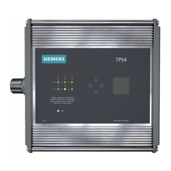
TPS4 13 Operation LED Operation • Each SPD contains 2 dual color LEDs per phase shown in the appropriate voltage configuration. • True 10-mode versions will have 3 LEDs per phase. • When the LEDs are green complete protection is present. - Page 8 TPS4 13 Adjust Date Screen The Adjust Date Screen will allow you to set the date of the SPD. Use the UP/DOWN buttons to adjust the value in the selected field until you have the correct value. Pressing the CENTER button will advance the cursor to the next date field. Once the “Year”...
- Page 9 TPS4 13 About Screen The About Screen displays the manufacturer’s information, the model number and the serial numberfor this specific SPD. Pressing the CENTER button will return you to the Main Menu Screen. System Info Screen The System Screen displays the important electrical information for this system. This includes the nominal operating voltage, System configuration (ie.
- Page 10 TPS4 13 Protection Loss When the SPD detects a Protection Loss this animation will be shown. It will remain on screen until acknowledged by an operator. Any subsequent events that occur while the disconnection event animation is on screen will be registered and queued for acknowledgment.
- Page 11 SPDs require minimal maintenance. We recommend periodic inspection of diagnostic indicators to ensure proper operation. We also recommend keeping the SPD clean as appropriate. Troubleshooting and Service Please contact Siemens Technical Support for any service related issues. We want to take care of any problems. INSTALLATION, OPERATION AND MAINTENANCE MANUAL...
- Page 12 3617 Parkway Ln only, and its effectiveness will be subject to specific variables including Peachtree Corners, GA 30092 field conditions and project parameters. Siemens reserves the right to United States of America modify the technology and product specifications in its sole discretion Telephone: +1 (800) 333-7421 without advance notice.