
Related Manuals for Janome CoverPro 3000 PROFESSIONAL


Summary of Contents for Janome CoverPro 3000 PROFESSIONAL
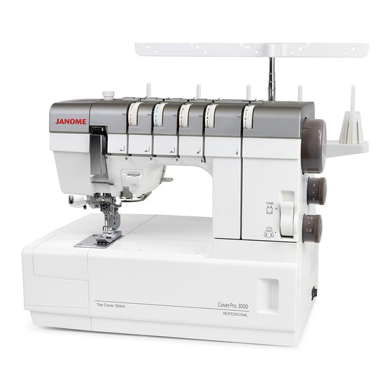
- Page 1 Sixth Edition: 12 October 2021 SERVICE MANUAL & PARTS LIST MODEL: CoverPro 3000 PROFESSIONAL (Continental Europe) (Australia) (UK)
- Page 2 First Edition: 25 May 2021 Modified info. Modified: 28 May 2021 P44-6: image added. P45-20: 624245001 Thrust stopper → 000038502 Washer Modified: 22 June 2021 P49-4: 778636014 → 778636003 P49-5: 778108012 → 778108001 Modified: 14 July 2021 Service manual: modified. Modified: 20 August 2021 P31: NOTE: Insert the 2 mm spacer o between the ring !0 and top cover stitch cam !1 to adjust the clearance.
-
Page 4: Table Of Contents
INDEX Replacing the External Parts Face cover ............................. 1 Top Cover .............................. 2 Belt Cover .............................. 3 Free Arm Cover ............................. 4 Looper Cover ............................5 Base plate ............................. 6 Front Cover ............................7 Rear Cover ............................8 Mechanical Adjustment Presser Bar Height .......................... - Page 5 INDEX Replacing the External Parts Face cover ............................. 1 Top Cover .............................. 2 Belt Cover .............................. 3 Free Arm Cover ............................. 4 Looper Cover ............................5 Base plate ............................. 6 Front Cover ............................7 Rear Cover ............................8 Mechanical Adjustment Presser Bar Height ..........................
-
Page 6: Replacing The External Parts
Replacing the External Parts 1. Face cover To remove: z Remove the setscrew q. Place your finger in the groove w and slide the lamp arm cover e to the right. Remove the setscrew r. Disconnect the connector A t and connector B y. Remove the face cover u. To attach: x Follow the above procedures in reverse. -
Page 7: Top Cover
Replacing the External Parts 2. Top Cover To remove: z Raise the carrying handle q. Remove the setscrews w (2 pcs.). Remove the hooks e (6 pcs.). Remove the top cover r. To attach: x Follow the above procedures in reverse. -
Page 8: Belt Cover
Replacing the External Parts 3 . Belt Cover To remove: z Remove the setscrew q. Loosen the setscrews w (2 pcs.). Remove the belt cover e. To attach: x Follow the above procedures in reverse. -
Page 9: Free Arm Cover
Replacing the External Parts 4. Free Arm Cover To remove: z Pull the extension table q away from the machine. Remove the setscrews w (3 pcs.). Remove the free arm cover e. To attach: x Follow the above procedures in reverse. -
Page 10: Looper Cover
Replacing the External Parts 5. Looper Cover To remove: z Remove the setscrews q (2 pcs.) Remove the looper cover w (with a hinge attached). To attach: x Follow the above procedures in reverse. (View from the bottom side) -
Page 11: Base Plate
Replacing the External Parts 6. Base plate To remove: z Loosen the setscrews q (2 pcs.). Remove the hinge screws w (3 pcs.), washers 5 e (3 pcs.), rubber feet r (3 pcs.) and rubber foot washers (3 pcs.) t. Remove the setscrews y (3 pcs.). Remove the base plate u. To attach: x Follow the above procedures in reverse. -
Page 12: Front Cover
Replacing the External Parts 7. Front Cover To remove: z Remove the face cover, top cover, belt cover, free arm cover and looper cover (see pages 1 to 5). x Loosen the setscrews q, w (2 pcs.). Remove the setscrews e (2 pcs.). Disconnect the connector r. Remove the front cover t. To attach: c Follow the above procedures in reverse. (View from the rear side) -
Page 13: Rear Cover
Replacing the External Parts 8 . Rear Cover To remove: z Remove the face cover, top cover and free arm cover (see pages 1, 2 and 4). x Remove the setscrews q (2 pcs.). Remove the spool stand w. Remove the setscrews e (2 pcs.). Remove the setscrews r (2 pcs.). Remove the rear cover t. To attach: x Follow the above procedures in reverse. -
Page 14: Mechanical Adjustment
Mechanical Adjustment 1. Presser Bar Height The distance between the bottom of the presser foot in up position and the needle plate should be 4.7 to 5.3 mm. z Remove the face cover (see page 1). x Raise the presser foot and loosen the hexagonal socket screw q. Place a block 5 mm w thick under the presser foot and lower the presser foot lifter e. c Tighten the hexagonal socket screw q firmly. NOTE: Make sure that the presser foot should be parallel to the feed dog slots r in the needle plate and should not interfere with the needles. v Attach the lamp set plate, front cover and face plate. 4.7 to 5.3 mm Should not interfere Should be parallel. -
Page 15: Presser Foot Pressure
2. Presser Foot Pressure The pressure adjusting screw should protrude 10 mm from the top of the machine. 10 mm z Turn the adjusting screw q to set its height at 10 mm. -
Page 16: Needle Bar Height
3. Needle Bar Height The distance between the point of the left needle (Schmetz ELx705, size 80/12) and the upper surface of the needle plate should be 7.8 to 8.2 mm when the needle bar is at the highest position. z Remove the face cover and top cover (see pages 1 to 2). 7.8 to 8.2 mm x Replace the left needle with Schmetz ELx705, size 80/12 needle q. c Turn the handwheel toward you to raise the needle bar to the highest position. v Lower the needle threader lever w to align the needle threader shaft hole e with the hexagonal socket screw r. Lower the needle threader lever w to align the needle b Loosen the hexagonal socket screw r and move threader shaft the needle bar t up or down to adjust the distance hole e with the at 8.0 mm. hexagonal socket screw r. -
Page 17: Feed Dog Height
4. Feed Dog Height Turn the handwheel toward you to raise the feed dog to its highest position. When the presser foot is lowered, the maximum height of the feed dog should be 0.9 to 1.1 mm above the needle plate. 0.9 to 1.1 mm z Set the stitch length dial at 3 and differential feed dial at 1.0. x Lower the presser foot and turn the handwheel toward you to raise the feed dog to its highest position. c Open the looper cover. Pull the looper release knob q and turn the looper the right. Loosen the setscrews w (4 pcs.). v Move the main feed dog e and sub feed dog r up or down to set the height at 1.0 mm. b Tighten the setscrews w (4 pcs.) firmly. Close the looper cover. -
Page 18: Looper Height
5. Looper Height The height of the tip of the looper should be 73.1 to 73.5 mm. z Remove the free arm cover (see page 4) and the needle plate. x Replace the right needle with the short test pin (28.3 mm long) q. c Turn the handwheel toward you to bring the looper w 73.1 to 73.5 mm to its rightmost position. v Pull the looper release knob e and turn the looper to the left. Loosen the setscrew r and move the looper up or down to match its point t with the tip y of the test pin. b Tighten the setscrew r firmly. n Replace the test pin with a regular needle. Attach the free arm cover and needle plate. -
Page 19: Looper Position
6. Looper Position The distance between the tip of the looper and center of the right needle should be 1.8 to 2.2 mm when the looper is at its rightmost position. z Remove the free arm cover (see page 4) and the needle plate. x Replace the right needle with the short test pin (28.3 mm long) q. 1.8 to 2.2 mm c Turn the handwheel toward you to bring the looper w to its rightmost position. v Loosen the setscrew e and move the looper to the left or right to adjust the distance between the test pin and tip of the looper to 2.0 mm. NOTE: Do not move the looper up or down otherwise the looper height will change. Use a stem r of the regular needle to check if there is a proper gap between the tip of the looper and test pin. n Tighten the setscrew e firmly. m Replace the test pin with a regular needle. Attach the free arm cover and needle plate. -
Page 20: Needle To Looper Timing
7. Needle to Looper Timing When the point of the looper meets with the right side 1.3 to of the needle on the right, the needle bar rises 1.3 to 1.5 mm 1.5 mm from the lowest position. z Remove the free arm cover (see page 4) and needle plate. x Replace the right needle with the long test pin (30.24 mm long) q. c Turn the handwheel toward you until the looper point w meets with the right side of the test pin. v Loosen the hexagonal socket screws e (2 pcs.) and turn the looper rocking cam r to match the looper 1.3 to 1.3 to point with the tip of the test pin. 1.5 mm 1.5 mm If the looper timing is too late t, turn the looper rocking cam r clockwise. If the looper timing is too early y, turn the looper rocking cam r counterclockwise. b Tighten the hexagonal socket screws e (2 pcs.) firmly. n Replace the test pin with a regular needle. -
Page 21: Clearance Between The Needle And Looper
8. Clearance between the Needle and Looper The clearance between the tip of the looper and scarf of the attached needle (Schmetz ELx705, size 80/12) 0 to 0.05 mm should be 0 to 0.05 mm. z Remove the free arm cover (see page 4) and needle plate. x Turn the handwheel toward you until the looper point q comes behind the needle. c Loosen the setscrews w and thrust the front needle guard e against the needle to make 0 to 0.05 mm clearance between the needle and tip of the looper. v Tighten the setscrews w and check the clearance. b Attach the free arm cover and needle plate. -
Page 22: Rear Needle Guard Height
0 to 0.05 mm 9. Rear Needle Guard Height The upper edge of the rear needle guard q should be 2.7 to 2.9 mm below the lower edge of the tip of the looper w when the tip of the looper e meets with the right side of the needle r. 2.7 to 2.9 mm z Remove the free arm cover and needle plate. x Turn the handwheel toward you until tip of the looper e matches with the right side of the needle. c Loosen the setscrews t and move the back needle 0.1 to 0.3 mm guard y up or down to set the upper edge q 2.8 mm below the lower edge w of the tip of the looper. v Turn the handwheel toward you slightly to bring the tip of the looper behind the needle. Check the clearance between the rear needle guard and the needle (Schmetz ELx705, size 80/12). It should be 0.1 to 0.3 mm. NOTE: If the clearance is out of the standard range, adjust it by re-positioning the front needle guard. -
Page 23: Needle To Feed Dogs Timing
10. Needle to Feed Dogs Timing The tip of the right needle should be 1.3 to 3.6 mm above the upper surface of the needle plate q when the top of the feed dogs w are same level with the upper surface of the needle plate q in its downward motion. 1.3 to 3.6 mm z Remove the free arm cover and rear cover. x Set the stitch length dial at 3 and differential feed dial at 1.0. c Turn the handwheel toward you to lower the needle bar until the tip of the left needle is 2.6 mm above the upper surface of the needle plate q. v Loosen the hexagonal socket screws e (2 pcs.) and turn the feed cam r to adjust the height of the feed dogs (see page 12). If the top of the feed dogs are higher than upper surface of the needle plate q, turn the feed cam r clockwise. If the top of the feed dogs are lower than upper surface of the needle plate q, turn the feed cam r counterclockwise. b Tighten the hexagonal socket screws e (2 pcs.). Attach the rear cover and free arm cover. -
Page 24: Stitch Length
11. Stitch Length The actual stitch length should be 3.0 to 3.2 mm (30 to 32 mm for 10 stitches q to !1 ) when the stitch length dial !2 is set to “3” and the differential feed dial !3 to “1.0”. z Set the stitch length dial !2 to “3” and the differential feed dial !3 to “1.0”. x Open the looper cover. Remove the belt cover (see page 3). c Sew 11 stitches on a piece of paper and measure the distance between the first stitch and eleventh stitch (10-stitch length). Fabric If the stitch length is longer than 32 mm, turn the adjusting screw !4 counterclockwise. If the stitch length is shorter than 30 mm, turn the adjusting screw !4 clockwise. v Measure the distance for 10 stitches again. Adjust until distance becomes 30 to 32 mm. 30 to 32 mm b Attach the belt cover. -
Page 25: Differential Feed Ratio
12. Differential Feed Ratio The main and sub feed dogs should move uniformly together when the stitch length dial is set at 3 and differential feed dial at 1.0. z Remove the belt cover (see page 3). x Set the stitch length dial at 3 and differential feed dial at 1.0. c Turn the adjusting screw q to adjust the differential feed ratio. If the sub-feed dog moves less than the main feed dog does, turn the adjusting screw clockwise. If the sub-feed dog moves more than the main feed dog does, turn the adjusting screw counterclockwise. NOTE: When the differential feed ratio is properly adjusted, the feed link w become horizontal. v Attach the belt cover. -
Page 26: Thread Tension
13. Thread Tension The standard thread tension measured with the King brand white polyester thread (#50) should be as below: z Remove the top cover (see page 2). Place your finger in the groove q and slide the lamp arm cover w to the right. x Turn the adjusting plate e to adjust the tension. If the tension is too loose, turn the adjusting plate clockwise. If the tension is too tight, turn the adjusting plate counterclockwise. c Attach the front cover, belt cover, top cover and face cover. Pull the adjusting plate e with your fingers, then shift Dial Thread tension Tension Value the adjusting plate e r Left in direction of arrows. needle 85 to 95 gf thread t Center needle 65 to 75 gf thread y Right needle 55 to 65 gf thread u Top needle 5 to 9 gf... -
Page 27: Motor
14. Motor To replace: z Remove the belt cover and rear cover (see pages 3 and 8). x Remove the setscrews q (2 pcs.)and machine socket cover w. c Remove the setscrews e (2 pcs.)and machine socket r. v 120V: Disconnect the motor cord (black) t and motor cord (white line) y from the 7 to 9 mm connector tabs u (2 pcs.). 220 to 240V: Disconnect the motor cord (brown) i 300 gf and motor cord (blue) o from the connector tabs !0 (2 pcs.). b Remove the setscrews !1 (2 pcs.). -
Page 28: Thread Take-Up Lever
15. Thread take-up lever Turn the fine mode switching lever to “STD“. The distance between the U-shape q of the thread guide w and the V-shape e of the thread take-up lever r should be 0.4 to 0.8 mm when the thread take- up lever is at its lowest position. z Remove the face cover and top cover (see pages 1 and 2). x Turn the handwheel toward you to lower the thread take-up lever r to its lowest position. c The distance between the U-shape q of the thread guide and the V-shape e of the thread take-up lever should r be 0.6 mm as shown. If not, loosen the setscrew t. Adjust the thread guide position up or down. v Tighten the setscrew t. U-shape Setscrew Thread guide Thread take- up lever 0.4 to 0.8 mm V-shape... -
Page 29: Replacing The Needle Threader
16. Replacing the needle threader When replacing the needle threader, adjust the hook position as well. z Be sure that the needle bar height is correct (see page 11). x Remove the face cover, top cover (see pages 1 to 2). c Replace the Schmetz ELx705, size 90/14 needle with the Schmetz ELx705, size 80/12 needle. v Lower the presser foot lifter. Turn the handwheel toward you to raise the needle at its highest position. Lower the needle threader lever q. Adjust the horizontal hook position, and the vertical hook position so that the hook w goes through the center needle hole e. Adjusting the horizontal hook position Loosen the setscrew r to move the nut t to adjust the hook position. Tighten the setscrew r after the adjustment. (View from the rear side) Adjusting the vertical hook position Loosen the hexagonal socket screw y and move the needle threader position plate u up or down to adjust the needle threader hook w height. -
Page 30: Adjusting Needle Threader Switch Lever
17. Adjusting needle threader switch lever Make the following adjustment (16. Replacing the needle threader) after making the adjustment on the previous page. z Remove the face cover, top cover (see pages 1 to 2). x Replace the Schmetz ELx705, size 90/14 needle with the Schmetz ELx705, size 80/12 needle. c Turn the handwheel toward you to raise the needle bar at its highest position. Lower the needle threader lever q. Be sure that the hook w goes through the center needle hole. Adjusting needle threader switch lever horizontal position (left needle) Switch the lever to L e. Lower the needle threader lever q. Turn the needle threader eccentric pin (left) r left or right to adjust the threader hook position so that the hook w goes through the left needle eye t. Adjusting needle threader switch lever horizontal position (right needle) Switch the lever to R y. -
Page 31: Replacing The Top Cover Stitch Mechanism Unit
18. Replacing the top cover stitch mechanism unit NOTE: To replace the top cover stitch mechanism, see pages 27 to 31 in order. To remove: z Remove the face cover, top cover, belt cover, free arm cover and rear cover (see pages 1 to 4 and 8). x Remove the top cover stitch cam spring q and backlash removal spring w. Remove the snap ring e. c Lower the top cover stitch lever. Remove the setscrews r (3 pcs.). v Remove the top cover stitch mechanism unit t. To attach: b Follow the above procedures in reverse. NOTE: Make the adjustment on pages 27 to 31 in order after replacing the top cover stitch mechanism unit. -
Page 32: Adjusting The Top Cover Stitch Mechanism Unit 1
19. Adjusting the top cover stitch mechanism unit 1 NOTE: Make the adjustment on pages 27 to 31 in order after replacing the top cover stitch mechanism unit. Adjusting the TC thread guide position Adjust the TC thread guide q position so that the inner edge of TC thread guide w aligns with the right edge of the top cover needle bar thread guide e. z Before proceeding the adjustment: ・Be sure that the needle bar height is correct (see page 11). x Remove the face cover, top cover, belt cover, free arm cover and rear cover (see pages 1 to 4 and 8). c Replace the Schmetz ELx705, size 90/14 needle with the Schmetz ELx705, size 80/12 needle. v Lower the top cover stitch lever. Turn the handwheel toward you to lower the needle at its lowest position. b Adjust the TC thread guide q position so that the inner edge of TC thread guide w aligns with the right edge of the top cover needle bar thread guide e. When the TC thread guide position is right of the inner edge・・・Turn the hexagonal socket screw r to clockwise When the TC thread guide position is left of the... -
Page 33: Adjusting The Top Cover Stitch Mechanism Unit 2
20. Adjusting the top cover stitch mechanism unit 2 NOTE: Make the adjustment on pages 27 to 31 in order after replacing the top cover stitch mechanism unit. Clearance between the TC thread guide and the spreader The clearance between the inner edge of TC thread guide q and the tip of the spreader w is 0.1 to 0.5 mm when the spreader e is rightmost position. z Before proceeding the adjustment: ・Be sure the needle bar height is correct (see page 11). 0.1 to 0.5 mm ・Be sure that the TC thread guide position is correct (see page 27). x Remove the face cover, top cover, belt cover, free arm cover and rear cover (see pages 1 to 4 and 8). c Replace the Schmetz ELx705, size 90/14 needle with the Schmetz ELx705, size 80/12 needle. v Lower the top cover stitch lever. -
Page 34: Adjusting The Top Cover Stitch Mechanism Unit 3
21. Adjusting the top cover stitch mechanism unit 3 NOTE: Make the adjustment on pages 27 to 31 in order after replacing the top cover stitch mechanism unit. Adjusting the spreader height and the clearance between left needle and the spreader The clearance between the left needle q and the spreader w is 0.8 to 1.2 mm (see Fig. 1). The height of spreader (The distance between the lower edge of the spreader e and the upper edge of the needle plate r) is 8.1 to 8.5 mm (see Fig. 2). z Before proceeding the adjustment: ・Be sure the needle bar height is correct (see page 11). ・Be sure that the TC thread guide position is correct (see page 27). ・Be sure that the clearance between the TC thread guide and the spreader is correct (see page 28). x Remove the face cover, top cover, belt cover, free arm cover and rear cover (see pages 1 to 4 and 8). -
Page 35: Adjusting The Top Cover Stitch Mechanism Unit 4
22. Adjusting the top cover stitch mechanism unit 4 (View from the left side) NOTE: Make the adjustment on pages 27 to 31 in order after replacing the top cover stitch mechanism unit. Adjust the front edge of the TC Adjusting the spreader and TC thread guide position thread guide q aligns with the Adjust the front edge of the TC thread guide q position front edge of the spreader w. so the front edge aligns with the front edge of the spreader w. The clearance between the lower edge of the TC thread guide e and the upper edge of the spreader r is 0.8 to 1.2 mm. z Before proceeding the adjustment: ・Be sure the needle bar height is correct (see page 11). ・Be sure that the TC thread guide position is correct (see page 27). ・Be sure that the clearance between the TC thread guide and the spreader is correct (see page 28). ・Be sure that the adjusting the spreader height and the clearance between left needle and the spreader is correct (see page 29). -
Page 36: Adjusting The Top Cover Stitch Mechanism Unit 5
23. Adjusting the top cover stitch mechanism unit 5 NOTE: Make the adjustment on pages 27 to 31 in order after replacing the top cover stitch mechanism unit. Adjusting the spreader and left needle timing The clearance of the tip of the left needle q and the upper edge of the needle plate w should be 2.2 to 2.6 mm when the spreader e is moving from the right side and the tip of the spreader r meets the left edge of the left needle t. z Before proceeding the adjustment: The tip of the ・Be sure the needle bar height is correct (see spreader page 11). should match ・ Be sure that the TC thread guide position is correct with the left (see page 27). side of the ・ Be sure that the clearance between the TC thread left needle guide and the spreader is correct (see page 28). ・... - Page 37 MODEL: CoverPro 3000 PROFESSIONAL (Continental Europe) (Australia) (UK) PARTS LIST...
- Page 38 MODEL: CoverPro 3000 PROFESSIONAL (Continental Europe) (Australia) (UK) PARTS LIST PARTS DESCRIPTION 778622006 Spool stand (unit) 778104007 Spool stand 784223105 Spool holder 778623007 Thread guide bar (unit) 000115700 Setscrew TP 4x10 000114802 Setscrew TP 4x12 778004A01 Rear cover 000081016 Setscrew 4x8...
- Page 39 MODEL: CoverPro 3000 PROFESSIONAL (Continental Europe) (Australia) (UK) PARTS LIST...
- Page 40 MODEL: CoverPro 3000 PROFESSIONAL (Continental Europe) (Australia) (UK) PARTS LIST PARTS DESCRIPTION 778612003 Top cover (unit) 778082A01 Top cover 797047103 Thread guide cover 797048012 Thread guide spring 797049002 Cushion 795004102 Carrying handle 778083009 Handle supporter 730015002 Handle fixing plate pin...
- Page 41 MODEL: CoverPro 3000 PROFESSIONAL (Continental Europe) (Australia) (UK) PARTS LIST...
- Page 42 MODEL: CoverPro 3000 PROFESSIONAL (Continental Europe) (Australia) (UK) PARTS LIST PARTS DESCRIPTION 778005007 Free arm cover 000081005 Setscrew 4x8 778006008 Extension table 778103A01 Belt cover 000101703 Setscrew 4x12 795112104 Base plate 866630003 Rubber foot (unit) 866070009 Rubber foot washer 797363016...
- Page 43 MODEL: CoverPro 3000 PROFESSIONAL (Continental Europe) (Australia) (UK) PARTS LIST...
- Page 44 MODEL: CoverPro 3000 PROFESSIONAL (Continental Europe) (Australia) (UK) PARTS LIST PARTS DESCRIPTION 778610001 Front cover (unit) 778076A01 Front cover 778077000 Top cover stitch thread guide 1 795040018 Needle thread guide (1) 795192005 Needle thread guide 000149312 Setscrew 3x8 (B) 795042009...
- Page 45 MODEL: CoverPro 3000 PROFESSIONAL (Continental Europe) (Australia) (UK) PARTS LIST...
- Page 46 MODEL: CoverPro 3000 PROFESSIONAL (Continental Europe) (Australia) (UK) PARTS LIST PARTS DESCRIPTION 778639006 Face cover set plate (unit) 778062002 Face cover set plate 778515005 Printed circuit board U (unit) 000101116 Setscrew 3x4 778516006 Relay harness (unit) 000115205 Setscrew TP 4x6...
- Page 47 MODEL: CoverPro 3000 PROFESSIONAL (Continental Europe) (Australia) (UK) PARTS LIST...
- Page 48 MODEL: CoverPro 3000 PROFESSIONAL (Continental Europe) (Australia) (UK) PARTS LIST PARTS DESCRIPTION 778616007 Thread tension set plate (unit) 778097006 Thread tension set plate 778507004 Needle thread tension (L) (unit) 778520003 Needle thread tension (C) (unit) 778521004 Needle thread tension (R) (unit)
- Page 49 MODEL: CoverPro 3000 PROFESSIONAL (Continental Europe) (Australia) (UK) PARTS LIST...
- Page 50 MODEL: CoverPro 3000 PROFESSIONAL (Continental Europe) (Australia) (UK) PARTS LIST PARTS DESCRIPTION 795613100 Looper shaft (unit) 795092004 Looper shaft 795614101 Looper (unit) 778095004 Front needle guard 000078320 Setscrew 3x6 792048006 Looper shaft ring 795099012 Looper link arm 795101007 Looper release knob...
- Page 51 MODEL: CoverPro 3000 PROFESSIONAL (Continental Europe) (Australia) (UK) PARTS LIST...
- Page 52 MODEL: CoverPro 3000 PROFESSIONAL (Continental Europe) (Australia) (UK) PARTS LIST PARTS DESCRIPTION 795611038 Feed adjuster bracket (unit) 652056000 Adjusting screw 785224006 Adjusting screw 000160102 Adjustable lock nut 4 795087D01 Stitch length dial 795087D02 Differential feed dial 794099905 Dial cap 787263003...
- Page 53 MODEL: CoverPro 3000 PROFESSIONAL (Continental Europe) (Australia) (UK) PARTS LIST 19 20...
- Page 54 MODEL: CoverPro 3000 PROFESSIONAL (Continental Europe) (Australia) (UK) PARTS LIST PARTS DESCRIPTION 778614005 Upper shaft (unit) 731384008 Felt 000111201 Hexagonal socket screw 4x4 778636003 Top cover stitch cam (unit) 778108001 Top cover stitch cam 778114000 Ring 000111108 Hexagonal socket screw 4x6...
- Page 55 MODEL: CoverPro 3000 PROFESSIONAL (Continental Europe) (Australia) (UK) PARTS LIST...
- Page 56 MODEL: CoverPro 3000 PROFESSIONAL (Continental Europe) (Australia) (UK) PARTS LIST PARTS DESCRIPTION 778618607 Machine socket (whole unit) (Continental Europe) 778618700 Machine socket (whole unit) (Australia) (UK) 778620004 Motor (unit) (Continental Europe) 778620107 Motor (unit) (Australia) (UK) 778511001 Motor 777502109 Machine socket (unit)
- Page 57 MODEL: CoverPro 3000 PROFESSIONAL (Continental Europe) (Australia) (UK) PARTS LIST...
-
Page 58: Parts List
MODEL: CoverPro 3000 PROFESSIONAL (Continental Europe) (Australia) (UK) PARTS LIST PARTS DESCRIPTION 778870001 Standard accessories (unit) 778805005 Needle case (unit) 784810002 Screwdriver (large) 792030005 Screwdriver (small) 624801001 Tweezers 624806006 822020503 Spool cap 802424004 Lint brush 797813005 Tension release clip 202024002...